
Embedded Programming
Introduction
For this week we had to:
read a microcontroller data sheet program your board to do something, with as many different
programming languages
and programming environments as possible (individual assignment)
compare the performance and development workflows
for other architectures (group assignment)
Datasheet
Here's the ATtiny44a
datasheet
The first thing I did was to figure out whar AVR means, and in the book
Practical
AVR Microcontrollers by Alan Trevennor
I learned that nobody at Atmel wants to tell what the AVR stand for. The inventors of AVR Alf
Egil Bogen and Vegard Wollan even made a teasing video The Story of AVR.
This week was very stressful for me since I felt depleted and neither of my soldered
microcontrollers worked.
While trying to understand the datasheet I learned this concepts:
In System Programming is achieved via SPI port (Serial
Peripheral Interface).
Here are the 4 wire names of SPI:
SCLK: Serial Clock (output from master)
MOSI-Master Out Slave In (data output from master)
MISO-Master In Slave Out (data output from slave)
SS: Slave Select (output from master) This is used for communicating with several
microcontrollers.
SPI is A full-duplex
(FDX) system, or sometimes called double-duplex, which allows communication in both directions,
and, unlike half-duplex, allows this to happen simultaneously.
If some pins are unused, it is recommended to ensure that these pins have a defined level.
Page 55
Programming Solar Tracking board (Final Project)
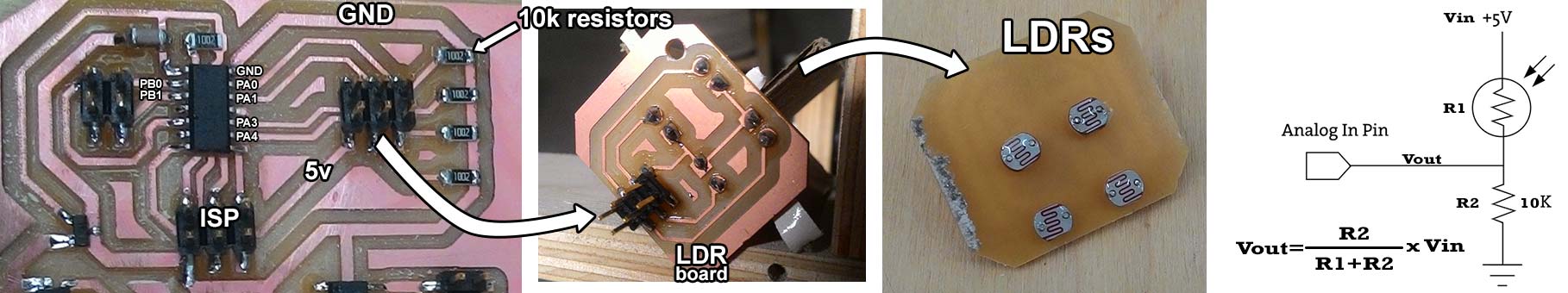
My final project has two different programs that work on different ATtiny44 microcontrollers. The
first one sun.44.c measures voltage from 4 LDR's
(Light
Dependent Resistor)
and the second one dc.44.c gets commands from the first microcontroller and drives the DC motors
accordingly.
I used Neil's programs: hello.light.45.c
, hello.H-bridge.44.DC.c
and hello.RGB.45.c
as a reference.
The program sun.44
Let's begin with sun.44.c. With this program ATtiny44 measures voltage coming from 4 LDRs with 4 analog inputs (PA0,PA1,PA3,PA4) based on this voltage readings the outputs PB0 and PB1 change their states to High (5v) and low(0). The voltage is measured using the voltage divider principle.
Let's understand the c code:
#include avr/io.h // This is the library for AVR
device-specific Input Output definitions
#include util/delay.h // This is the library of functions
for busy-wait delay loops.
Next come the definition of macros #define
directive allows the definition of macros.
|= is "Bitwise inclusive OR and assignment operator" (A |= B) is the same as (A = A | B).
&= is "Bitwise AND assignment operator" (A &= B) is the same as (A = A & B).
<< is "Binary Left Shift Operator" if A=0001 (A << 1)=0010.
#define output(directions,pin) (directions |= pin) // set port direction for
output
#define set(port,pin) (port |= pin) // set port pin
#define clear(port,pin) (port &= (~pin)) // clear port pin
#define pin_test(pins,pin) (pins & pin) // test for port pin
#define bit_test(byte,bit) (byte & (1 << bit)) // test for bit set
#define PWM_delay() _delay_us(500) // PWM delay 500ms
#define led_port PORTB // this assigns led_port to PORTB
// (whenver compiler sees led_port it understands PORTB)
#define led_direction DDRB // this assigns led_direction to be DDRB
// (whenver compiler sees led_direction it understands DDRB)
#define red (1 << PB1) // this assigns red to be 1 binary left shifted by
PB1
#define blue (1 << PB0) // this assigns blue to be 1 binary left shifted by
PB0
//Then come the function declarations.
void initADCul(){ // declares initADCul as a function. we got 4 functions initADCul, initADCur, initADCdl, initADCdr where
//last 2 letters mean ul-upper left, ur-upper right, dl-down left, dr-down right (LDRs). This
//functions initiate and define ADCs(analog to digital converters) for each pin respectively.
ADMUX = (0 << ADLAR) | (0 << REFS1) | (0 << REFS0) | (0 << MUX3) | (0 << MUX2) | (0 << MUX1) | (0 << MUX0);
//ADMUX is "ADC Multiplexer Selection Register"
//it is used to select reference voltage, to select
//the ADC port and the way data should be stored.
//(0 << ADLAR) sets ADC Left Adjust Result
//(0 << REFS1) | (0 << REFS0) sets reference voltage to VCC
//(0 << MUX3) | (0 << MUX2) | (0 << MUX1) | (0 << MUX0) sets ADC0 (PA0) as analog input.
//This 4 bits define which ADC to read. In our example we
//use ADC0, ADC1, ADC3, ADC4. Just imagine 4 bits each could be 0 or 1,
//this bits represent powers of 2 for example
//0000 is ADC0 because 0+0+0+0=0, 0001 is ADC1 because 0+0+0+2^1=1, 0011 is ADC3
//because 0+0+2^1+2^0=3. 0100 is ADC4 because 0+2^2+0+0=4.
ADCSRA= (1 << ADEN) | (1 << ADPS2) | (1 << ADPS1) | (0 << ADPS0);
//This register is responsible for enabling and starting ADC and prescaler selection.
//(1 << ADEN) Enables ADC
//(1 << ADPS2) | (1 << ADPS1) | (0 << ADPS0) sets prescaler to 64.
// Then comes the main part:
int main(void) {
CLKPR = (1 << CLKPCE); // enable a change to clock register
CLKPR = (0 << CLKPS3) | (0 << CLKPS2) | (0 << CLKPS1) | (0 << CLKPS0); // sets Clock Division Factor to 1
int ul = 0; // integer variable to store up left LDR value
int ur = 0; // integer variable to store up right LDR value
int dl = 0; // integer variable to store down left LDR value
int dr = 0; // integer variable to store down right LDR value
int au = 0; // integer variable to store average up value
int ad = 0; // integer variable to store average down value
int al = 0; // integer variable to store average left value
int ar = 0; // integer variable to store average right value
output(led_direction, red); //initialize output pin PB0
output(led_direction, blue); // initialize output pin PB1
while(1){ // Forever loop
initADCur(); // calles function for up right LDR
ADCSRA |= (1 << ADSC); // start ADC measurement
while (ADCSRA & (1 << ADSC) ); // wait till conversion complete
ur = ADCW; // writes PA0's reading in "ur" variable
initADCul(); // calles function for up left LDR
ADCSRA |= (1 << ADSC); // start ADC measurement
while (ADCSRA & (1 << ADSC) ); // wait till conversion complete
ul = ADCW; // writes PA1's reading in "ul" variable
initADCdr(); // calles function for down right LDR
ADCSRA |= (1 << ADSC); // start ADC measurement
while (ADCSRA & (1 << ADSC) ); // wait till conversion complete
dr = ADCW; //writes PA0's reading in "dr" variable
initADCdl(); // calles function for down left LDR
ADCSRA |= (1 << ADSC); // start ADC measurement
while (ADCSRA & (1 << ADSC) ); // wait till conversion complete
dl = ADCW; // writes PA0's reading in "dl" variable
au = (ul + ur)/2; // calculates average for upper LDRs
ad = (dl + dr)/2; // calculates average for down LDRs
al = (ul + dl)/2; // calculates average for left LDRs
ar = (ur + dr)/2; // calculates average for right LDRs
if (au > ad) {set(led_port,red);} // if average up is bigger than average down set PB0 High (5v).
else if (au < ad) {clear(led_port,red);} // if average up is less than average down set PB0 Low (0v).
if (al > ar) {set(led_port,blue);} // if average up is bigger than average down set PB1 High (5v).
else if (al < ar) {clear(led_port,blue);} // if average up is less than average down set PB1 Low (0v).
The program dc.44
#include avr/io.h // This is the library for AVR
device-specific Input Output definitions
#include util/delay.h // This is the library of functions
for busy-wait delay loops.
Next come the definition of macros #define
directive allows the definition of macros.
|= is "Bitwise inclusive OR and assignment operator" (A |= B) is the same as (A = A | B).
&= is "Bitwise AND assignment operator" (A &= B) is the same as (A = A & B).
<< is "Binary Left Shift Operator" if A=0001 (A << 1)=0010.
#define output(directions,pin) (directions |= pin) // set port direction for output.
#define set(port,pin) (port |= pin) // set port pin
#define clear(port,pin) (port &= (~pin)) // clear port pin
#define pin_test(pins,pin) (pins & pin) // test for port pin
#define bit_test(byte,bit) (byte & (1 << bit)) // test for bit set
#define input_port PORTB this assigns input_port to PORTB
// (whenver compiler sees input_port it understands PORTB)
#define input_direction DDRB // this assigns input_direction to be DDRB
// (whenver compiler sees input_direction it understands DDRB)
#define input_pino (1 << PB0) // this assigns input_pino to be 1 binary left shifted by
PB0
#define input_pini (1 << PB1) // this assigns input_pini to be 1 binary left shifted by
PB1
#define input_pins PINB // this assigns input_pins to be PINB.
#define bridge_port PORTA // H-bridge port
#define bridge_direction DDRA // H-bridge direction
#define IN1 (1 << PA0) // assign IN1 to PA0 (1st H-bridge)
#define IN2 (1 << PA1) // assign IN2 to PA1 (1st H-bridge)
#define IN3 (1 << PA3) // assign IN3 to PA3 (2nd H-bridge)
#define IN4 (1 << PA4) // assign IN4 to PA4 (2nd H-bridge)
// Then comes the main part:
int main(void) {
CLKPR = (1 << CLKPCE); // enable a change to clock register
CLKPR = (0 << CLKPS3) | (0 << CLKPS2) | (0 << CLKPS1) | (0 << CLKPS0); // sets Clock Division Factor to 1
clear(bridge_port, IN1); // sets IN1 to Low
output(bridge_direction, IN1); // sets IN1 as output
clear(bridge_port, IN2); // sets IN2 to Low
output(bridge_direction, IN2); // sets IN2 as output
clear(bridge_port, IN3); // sets IN3 to Low
output(bridge_direction, IN3); // sets IN3 as output
clear(bridge_port, IN4); // sets IN4 to Low
output(bridge_direction, IN4); // sets IN4 as output
set(input_port, input_pino); // turn on pull-up for PB0 (sets PB0 to High(5v))
set(input_port, input_pini); // turn on pull-up for PB1 (sets PB0 to High(5v))
input(input_direction, input_pino); // sets PB0 as input
input(input_direction, input_pini); // sets PB1 as input
while(1){ // Forever loop
if (0 != pin_test(input_pins,input_pino)){ // if PB0 is High(5v)
//The following two lines enable 1st H-bridge to turn 1st DC motor left
clear(bridge_port, IN1); // set IN1(PA0) to Low(0)
set(bridge_port, IN2);} // set IN2(PA1) to High(5v)
else { // if PB0 is Low(0)
//The following two lines enable 1st H-bridge to turn 1st DC motor right
clear(bridge_port, IN2); // set IN2(PA1) to Low(0)
set(bridge_port, IN1);} // set IN1(PA0) to High(5v)
if (0 != pin_test(input_pins,input_pini)){ // if PB1 is High(5v)
//The following two lines enable 2nd H-bridge to turn 2nd (tilt) DC motor up
clear(bridge_port, IN3); // set IN3(PA3) to Low(0)
set(bridge_port, IN4);} // set IN4(PA4) to High(5v)
else { // if PB1 is Low(0)
//The following two lines enable 2nd H-bridge to turn 2nd (tilt) DC motor down
clear(bridge_port, IN4); // set IN4(PA4) to Low(0)
set(bridge_port, IN3);} // set IN3(PA3) to High(5v)
Here are the c codes and make files:
sun.44.zip For light sensing
dc.44.zip For DC driver