Computer-Controlled Machining
Introduction
For this week we had to:
test runout, alignment, speeds, feeds, and toolpaths for your machine (group assignment)
make something big (individual assignment)
Safty is the number one priority!
Here's the ShopBot
User Guide
While working with any machine we should always learn how to STOP it before learning how
to start it.
During tool operation the SPACEBAR on your computer keyboard becomes a
Panic/Stop/Halt
button. Hitting it will immediately stop the tool’s movement.
ShopBot is also supplied with a STOP Button that you can place in a convenient
location on your tool. Hitting this button will stop the tool’s movement. On a PRSalpha
ShopBot or Buddy the STOP Button will also cut power to the spindle/router.
Never operate the tool when you are fatigued.
Always protect your eyes and ears when operating your ShopBot.
NEVER leave the tool unattended while it is running.
The machine we'll be using is Shopbot PRSalpha 96 x 48. It was very dirty when we first
approached, it was never properly maintained and was lubricated with different syntetic oils
rather than Lithum grease that comes with the machine.
The dust collector was full so we decided to empty it before cleaning the machine and
lubricating it.
Prepairing the files
At first I wanted to build a boat, and while doing my research about boatbuilding I learned that Shopbot was born for boatbuilding. After some more research I realised that one week and small amout of material is not enogh to build the boat I wanted. There were many more ideas, but I decided to make a parametric lantern to better understand and get used to parametric modeling and explore some joinery concepts. I used FreeCad Parametric Modeler to model my lantern.
Tolerance test and measuring the Kerf
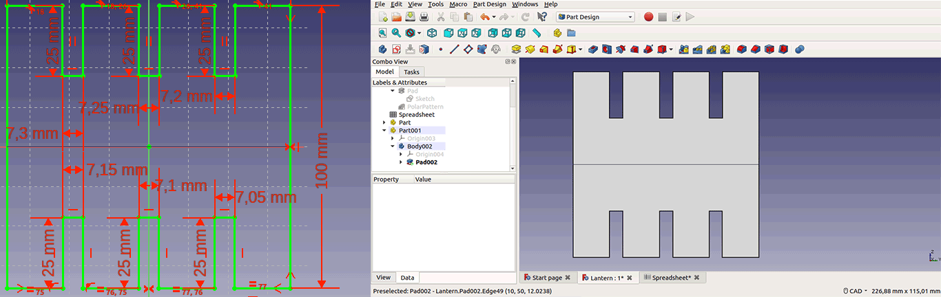
I'll be using halved joints for my lantern so I need to perform a tolerance test to find the perfect fit for my joints. My plywood material thickness was 7mm. I drew a rectangle and made 6 joints on it from 7mm to 7.3mm with 0.05mm difference.
I used VCarve Pro 9.5 to genrate toolpaths for shopbot. It's very intuitive and has lot's of tutorials out there. When you open a new project the first step is job setup that includes settings for:
- Job type -- here you got 3 options: Single sided, double sided, rotary. Our case is "Single Sided" because we will cut from one side of the material.
- Job size & units -- We use "mm". I used 7mm plywood 500x200mm for my test cut, this translates to Width(X)-500mm, Height(Y)-200mm and Thickness(Z)-7mm.
- Z zero position (!!!IMPORTANT!!!) -- we got 2 options here: Material Surface, Machine Bed. This option defines where machine Z zero is. Usually it is the "Material Surface" you want to choose, in this case you zero on the surface of the material you want to cut.
- XY datum position (!!!IMPORTANT!!!) -- we got many options here I choose the lowest left corner for convinience (that's the start point of material).
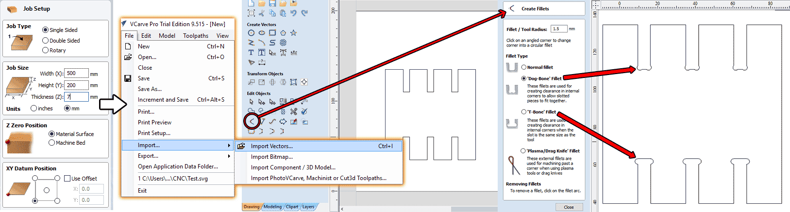
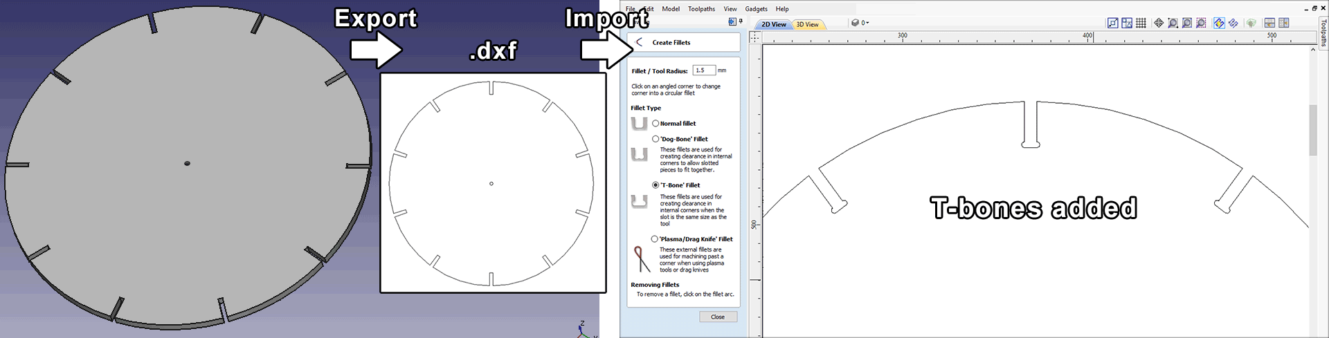
Whenever we try to cut inside corners we will face so called "inside corner problem" it's because we try to cut sharp corners with a rounded tool, the smaller the radius of the tool the less this problem's impact is. Fortunately there are genius solutions to this problem called "dog-bone" and "T-bone" more on this here Learn about Milling: The "Inside Corner" Problem. . There is a great tool in Vcarve Pro to add "dog-bones" and "T-bones" to your cut files. Find the "Create Fillets" from "Edit Objects" tools (image below), enter the radus of the tool you'll be using. Now select the "bone" type and click on the corner you want to become a "bone". I've added both "Dog-bones" and "T-bones" to my drawing to explore them but you can choose just one type.
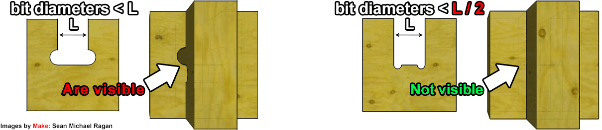
As you can see from the image above there are advantages and disadvantages for each type of "bone".
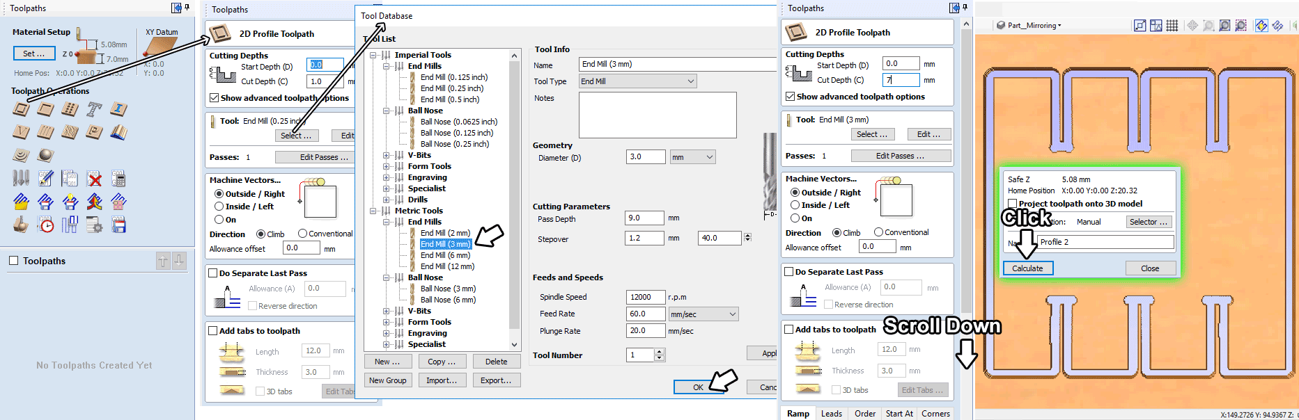
The next step is toolpath generation, find the Toolpath tab on the upper right corner, select the geometry and select "2D Profile Toolpath" (image below).
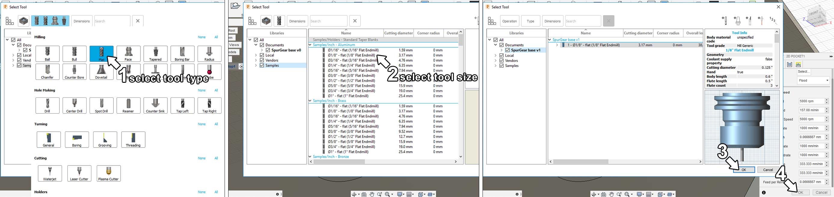
Then in "Cutting Depths" options set "Start Depth" to 0, "Cut Depth" to 7mm. Select the tool we will use metric tools and 3mm endmill.
Scroll down and select "Calculate". You can preview the result, after making sure everything is correct save the toolpath and load it to your machine.
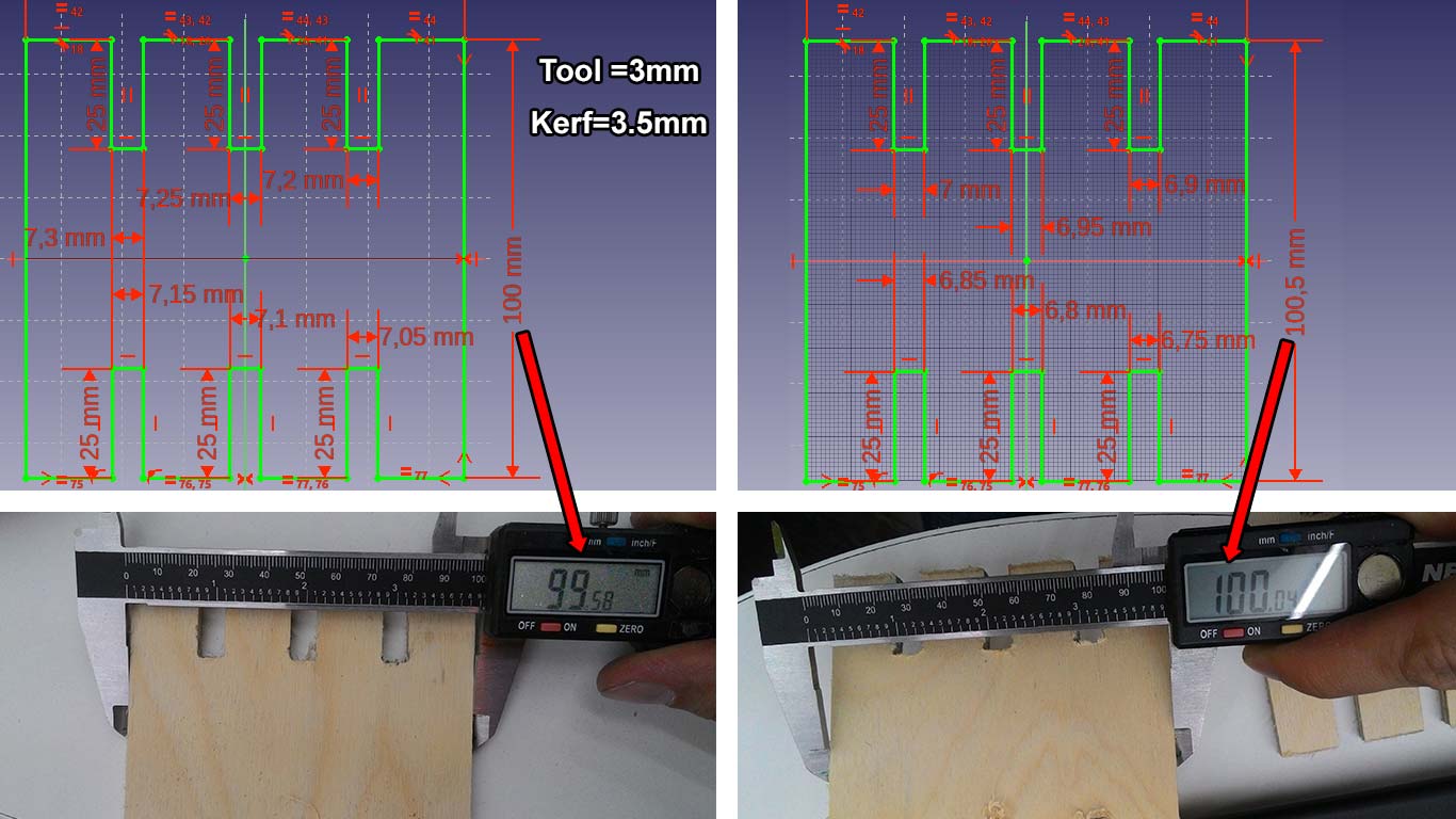
After cutting I measured the result and instead of 100mm it was 99.58mm. For the next test cut I changed the size to 100.5mm to compensate the deviation and to calculate the "kerf" also I changed joints width to be from 7mm to 6.75mm with 0.05mm difference. As you can see from the image below the size compesation worked and I got 100.04mm so we can conclude that the "kerf" is 3.5mm which is rather big.
After disscussing my results with my instructor Ohad Meyuhas I realised I did something wrong, because the kerf was very big. The potential reasons for my big kerf are:
1. The collets I used were in inches and my tool was in mm.
2. The tool was used before and maybe it was bent or worn out.
Anyway at that point I didn't knew that and I made a cut of my lantern base. Regarding the tolerance test 6.75mm was the perfect fit.
Lantern Design
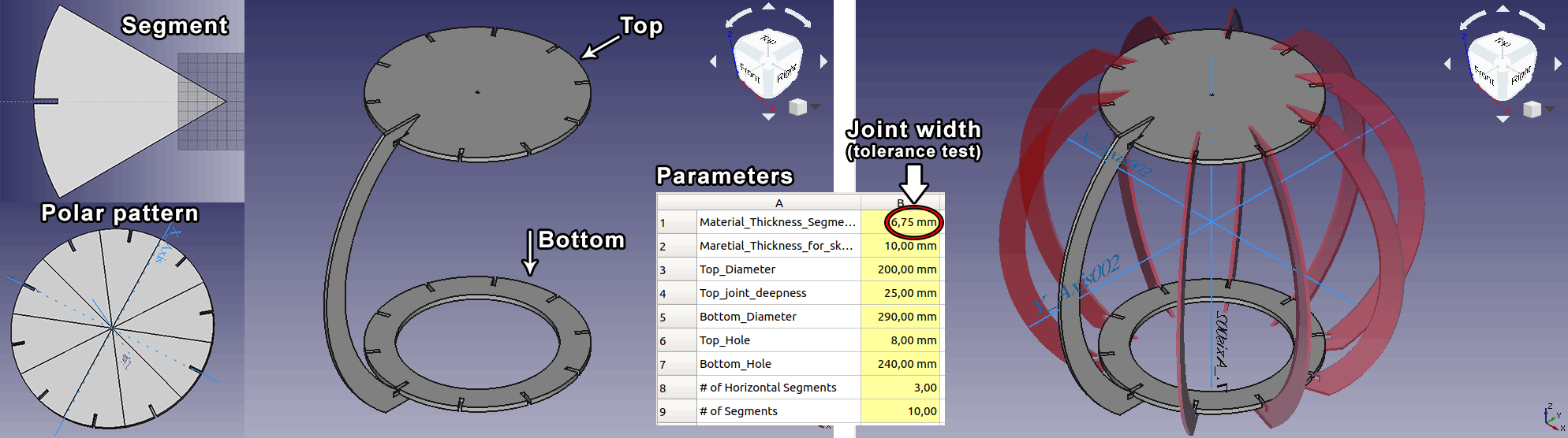
Learning Freecad takes time and effort, I spend my week trying and failing until I could get what I want. I explained parametric modeling with Freecad and how I modeled snap fit kit here. This design is based on the snap fit kid idea. There's a segment that has a parametric joint ("Material_Thickness_SEgment"=6.75mm) and parametric dimensions, then this segment is polar patterned using the "# of segments" parameter from spreadsheet (image below). Based on this there are two objects here "Top" and "Bottom". The "Top" part has a hole in the center that is also parametric see spreadhseed "Top_Hole", and the "Bottom" has a hole in the center "Bottom_Hole".
Then I exported the "Top" part as .dxf because as I mentioned above .svg had some problems. I imported .dxf as vector into Vcarve and added T-bones to the joint corners.
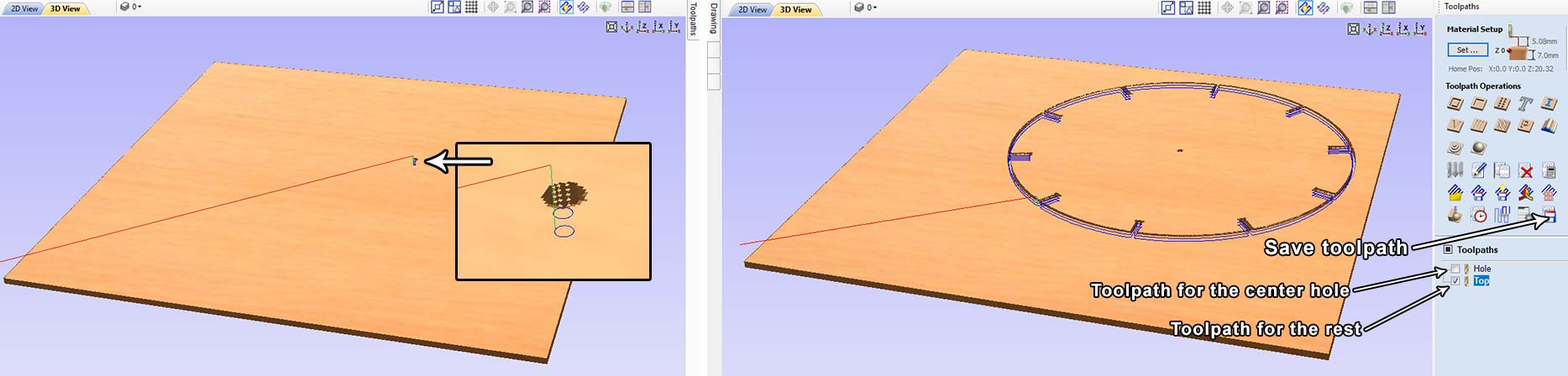
After adding T-bones I generated two toolpaths one for the center hole and the other for the rest of the part. I need this hole first to attach the part to the spoilboard with a screw then cut the rest of the part. To save the toolpaths separately select the toolpath you want by applying the checkbox and hit "save toolpath" (image below).
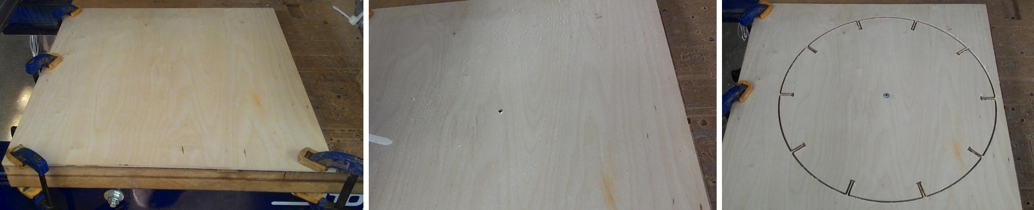
I made sure the spoilboard is clean and free of debris and clamped my material to it. I zeroed the tool and run the toolpath of the center hole. Then I drived a screw into the hole to keep the part stable while it's beeing cut, then I loaded the 2nd toolpath to cut the part.
Since my tool was downcut it left some thin layer of wood at the bottom but after slight sanding everything was perfectly clean.
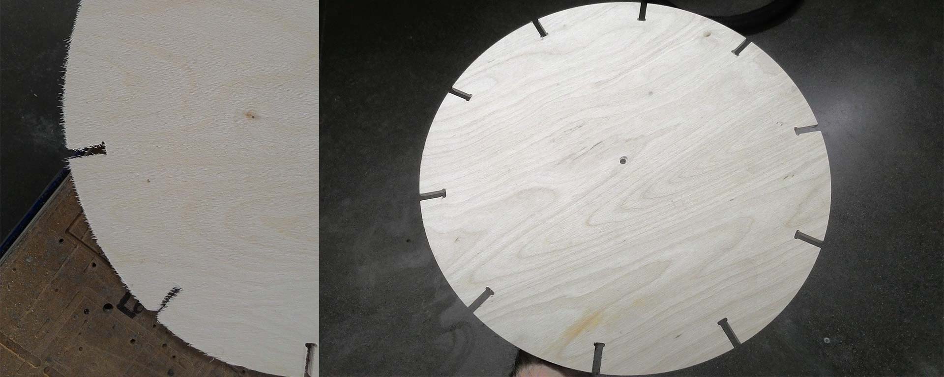
I was very satisfied with the result although I was out of time and this was all I managed to do during this week.
Here are the files:
Lantern.fcstd (Freecad file)
Test.svg (Tolerance test)
Top.dxf
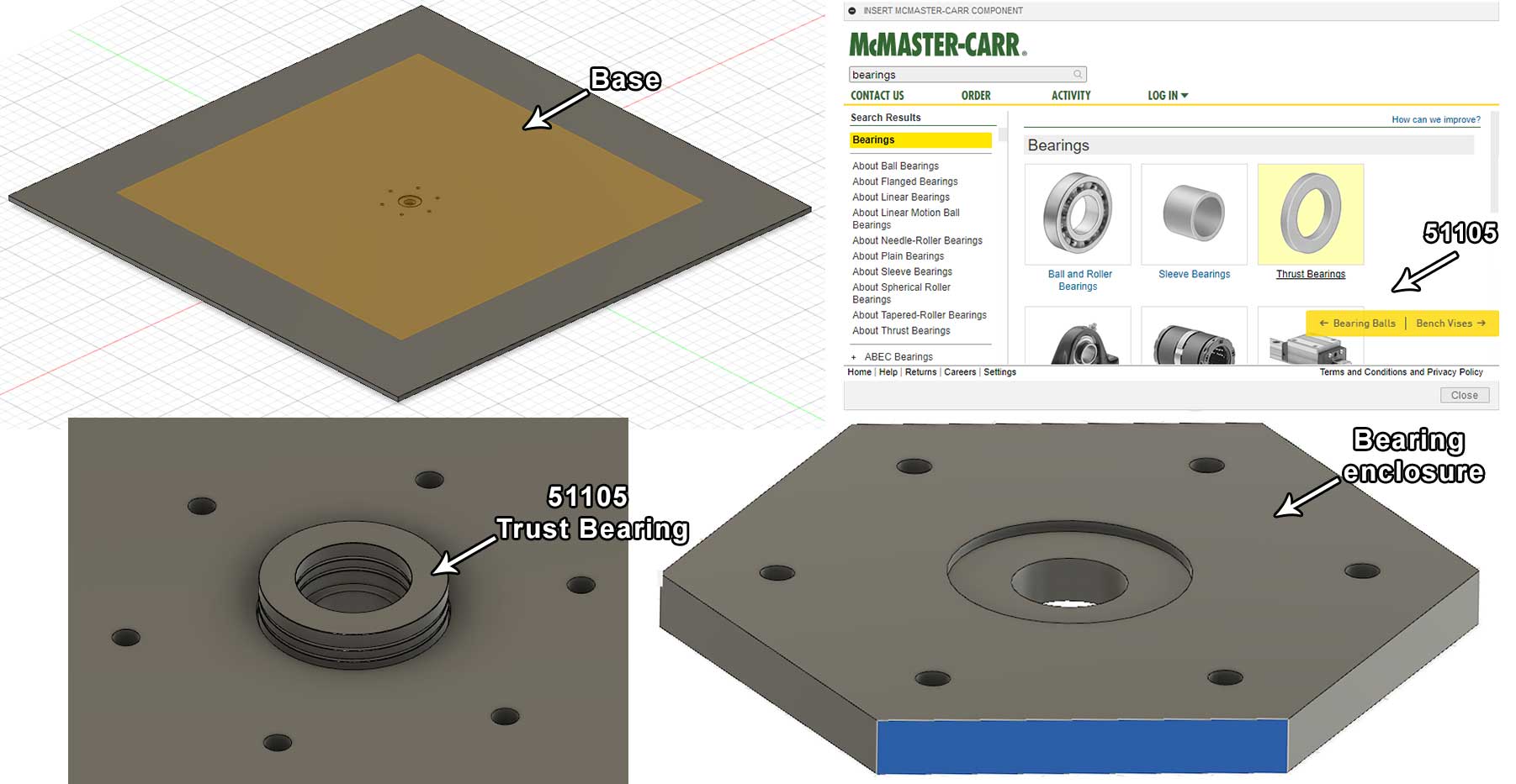
Solar Tracker body (Final Project)
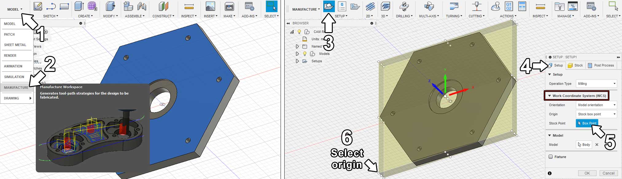
I really liked Freecad and I was convincing my friends who worked with Fusion and Inventer to try Freecad. I defintely will use it on regular basis, but since I was running out of time for my final project I decided to switch to Fusion 360. In my estimation Freecad vs Fusion 360 is like manual vs automatic transmission. The learning of Fusion is very easy and everything is intuitive, also it has CAM functionality.
Initialy I wanted to have a solar tracker with a parabolic mirror dish to concentrate the solar power, but at some point I realised that modeling and making the dish would take too much time. So I decided to make only the tracker system.