
Computer-Controlled Cutting
Vinyl Cutting
In this section I'll describe how to cut 13.56kHz RFID antenna with copper on vinyl cutting machine. The drawing process is described in week3. The abbreviation "RTFM" that Neil introduced us a week ago left a deep impression. So before touching the machine I found it's manual and took the time to read it.
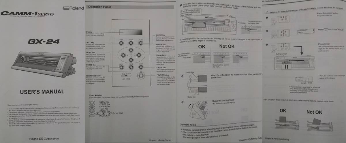
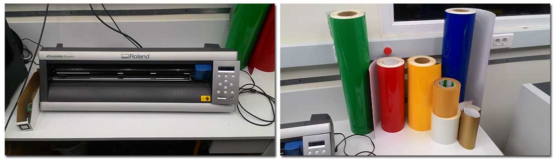
This is the machine Roland Gx-24 and it's vinyl rolls.
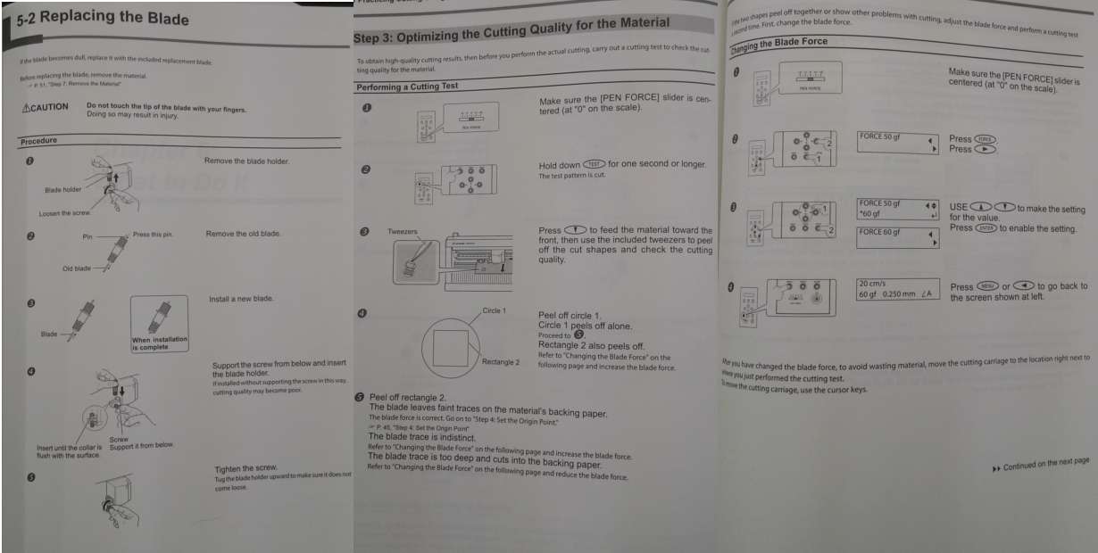
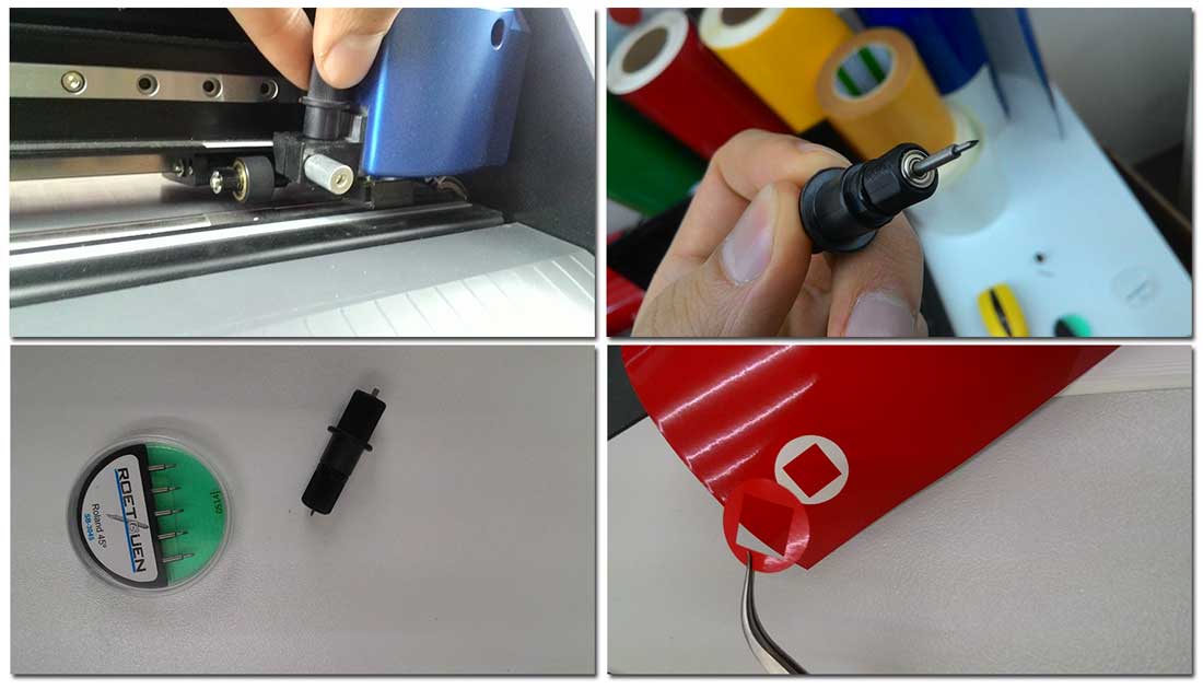
The blade was never changed in past 4 years so we decided to change the blade to new one to get best cuts. The angle of blades were 45 degrees. After installing the new blade and loading a piece of vinyl we did a test cut by long pressing the test button. According the manual it was perfect cut (The rectangle has to stay at it's place after removing the circle).
Unfortunately I couldn't find a linux driver for this machine so I booted my windows machine and
installed the driver.
After installing the driver and connecting the machine to my computer I've prepared the cut
files.
So here are 8 steps of using this machine:
1.Install the driver
2.Load a piece of media (vinyl, copper).
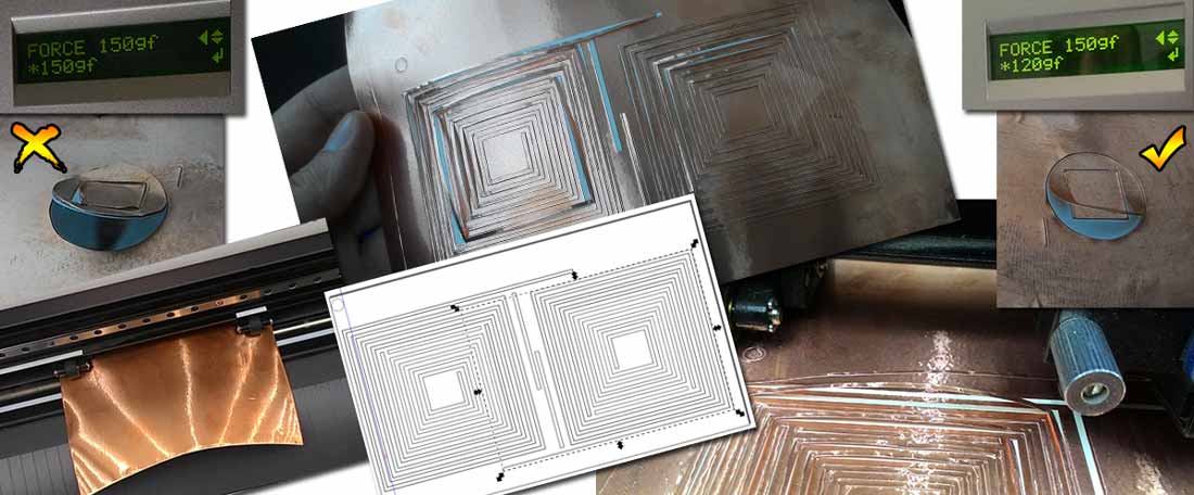
3.Make a test cut and adjust the cutting force.
4.Open Inkscape or other vector graphics software, create a document with the exact sizes
indicated on the little display of vinyl
cutter.
5.Put your vector files in the document boundaries (no fill, stroke size 0.01mm)
6.Hit Ctrl+P or find print in file menu make sure Roland Gx-24 is selected.
7.Open it's properties for cutting area hit Get from the machine, select the
units, hit OK.
8.Hit print.
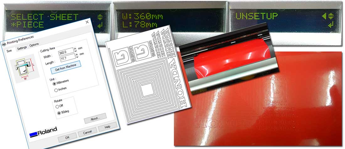
As it turned out, the force needed to cut vinyl was higher than for cutting copper. I reduced the force value 150gf each time by 10gf and performed test cut until I got the perfect cut on 120gf. After preparing the cut file I loaded the copper sheet and did the cut. I made two The first antenna turned out bad, but the second one was rather good.
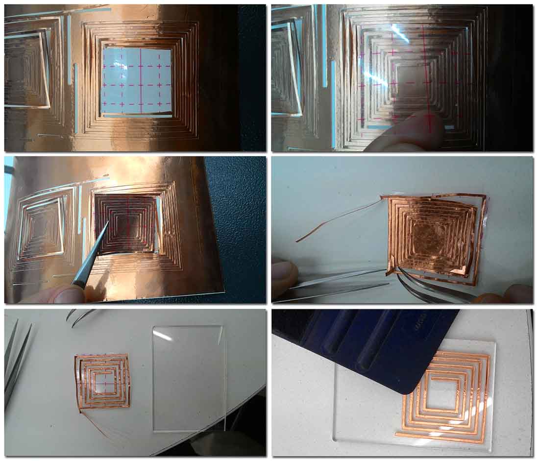
As I described in week3 I made a small antenna inside the big one to save material, but after cutting the material, I realized that it makes harder to get each antenna separately I measured the inner antenna size and made a little piece of transferring tape to take it out.
Laser Cutting (Group Project)
characterize your lasercutter, making test part(s) that vary cutting settings and dimensions.
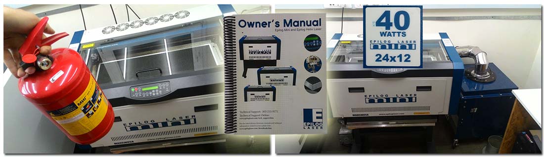
Our lasercutter is Epilog Mini 24 (40W CO2 laser with 24" x 12" engraving area).
The first thing we did together with Miqael
Aramyan we took the manual and took our time to carefully read it. The section
1
is about Safety that
consists of Laser Safety, Electrical Safety, Fire Safety.
In Laser Safety section we learned that this
device has
two lasers one high-power CO2 engraving laser and another one Laser Diode Pointer (Red Dot
Pointer). Also the
laser cabinet has safety interlocks that turn the laser off if the door is opened during
operation, and it's
important not to view directly into the beam of the Laser Diode Pointer (Red Dot Pointer).
In Electrical Safety section we learned that The AC input power to the Laser System is
potentially lethal. We
should never open any of the machine’s access panels while the unit is plugged in. We should
never make or break
any electrical connections to the system while the unit is turned on.
In the Fire Safety section we learned that some materials are extremely flammable and can
easily ignite and
burst into open flame setting the machine afire. So we should:
Stay with the laser. Never operate the laser system while unattended.
Be prepared with a fire extinguisher. Always keep a properly maintained and inspected
fire
extinguisher on hand.
Use Air Assist. Always use the system’s Air Assist feature when vector cutting.
Use caution when vector cutting.
Clean the laser. A buildup of cutting and engraving residue and debris is dangerous
and can create a
fire hazard in its own right.
Unfortunately this machine doesn't support linux so we had to switch back to windows in order to use this machine. We installed the driver on Miqael's PC and after ensuring that we have all necessary equipment, and precautions, we did our test cut. At first we were using autofocus but no matter what settings we tried the laser was flaming the cardboard and wasn't cutting all the way through. Here is a test cut with different settings we used color mapping for this task. Then we noticed that the little aluminum stick that performs autofocus test is broken. So we Set the focus manually with the Red Dot Pointer. And the cuts immediately became sharp and nice.

I used Freecad to make the tolerance test comb. To be honest it was not that easy the constraints were conflicting all the time. Here are the steps to create parametric design using Freecad.
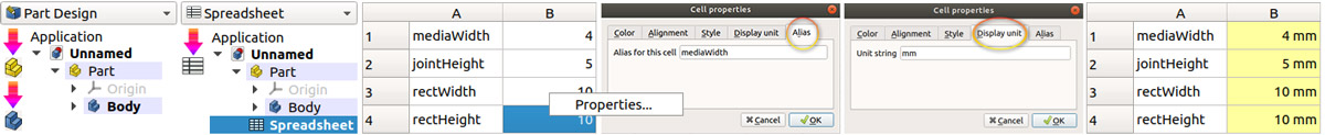
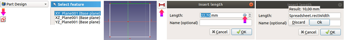
The next step is to create a sketch (select a plane), draw an object select a line and give it a constraint from the spreadsheet.
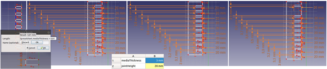
Clone the rectangle 9 times, change each rectangles height to be =spreadsheet value + 0.1 and increase by 0.1 on every next rectangle. Then for the convenience make a space between the last two biggest ones which are 4.9mm and 4.8mm this little step enables us to always know which side is the biggest one.
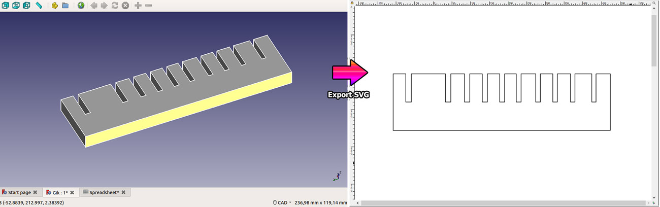
I extruded the sketch to illustrate the comb in 3d and finally export it to .svg
After measuring the media thickness I did the final cut.
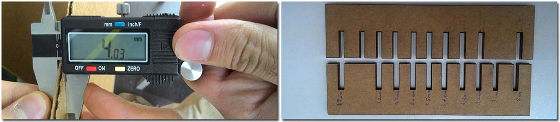
I made two different ones one from 4mm-4.9mm, and one from 3mm-3.9mm with step of 0.1mm. As it turned out the first one 4mm-4.9mm was not necessary. And the perfect fit was at 3.8mm
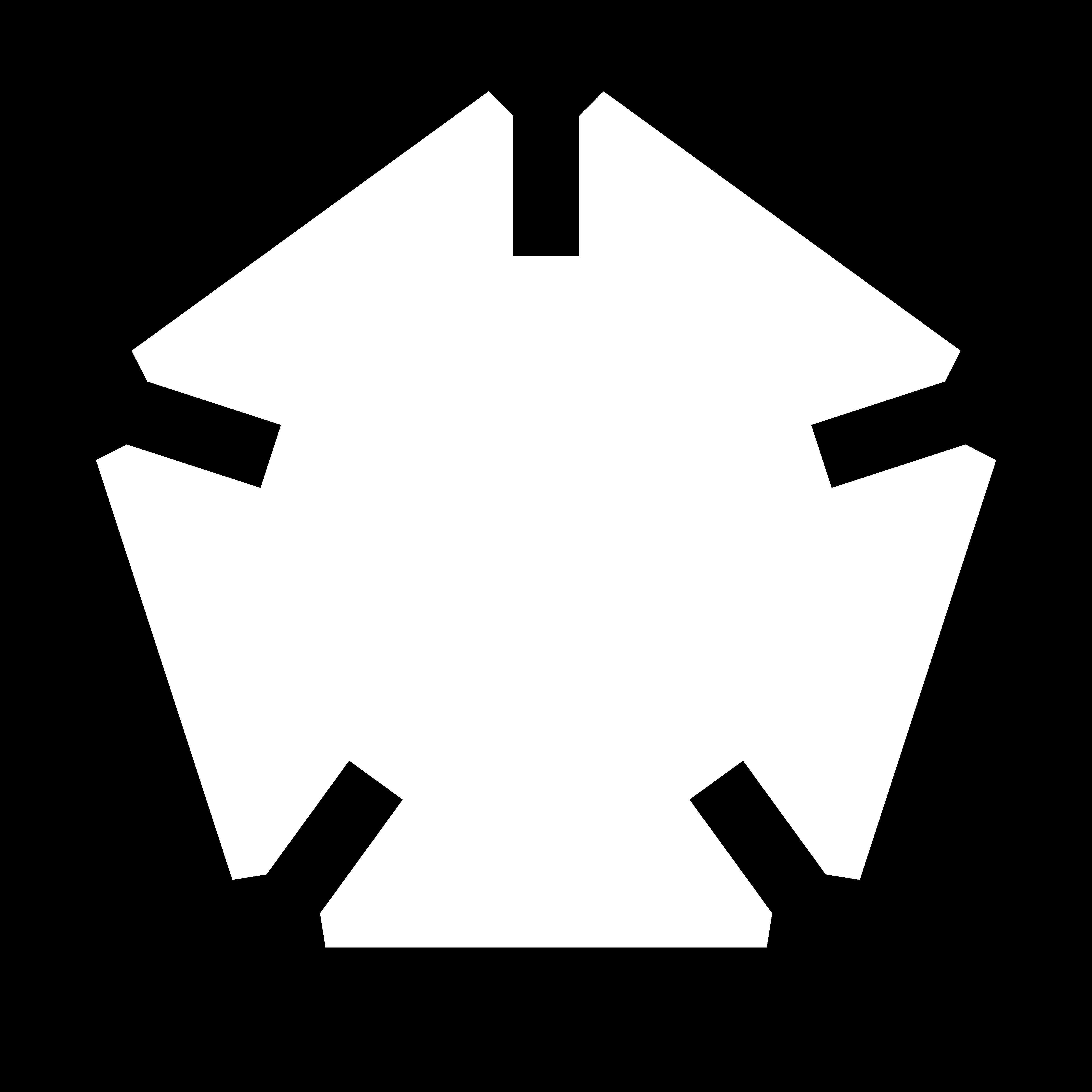
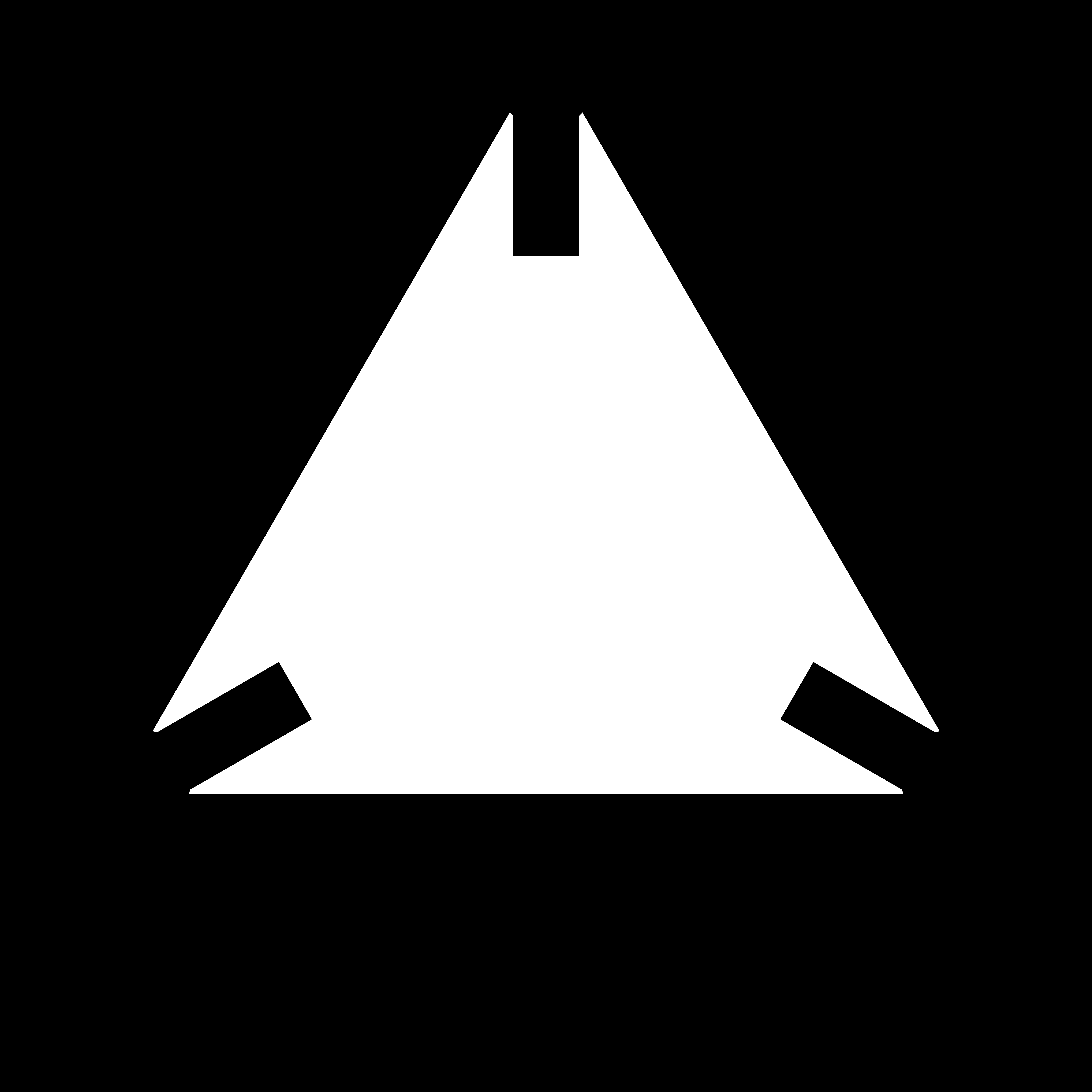
After tolerance test I tried to make a parametric snap fit kit with freecad but after a while I decided to use Antimony. Then I found this wonderful video.
As you can see it's very easy to use Antimony. Right click and select 2D>>Polygon then add 2D>>Rectangle and Triangle. The rectangle will be the joint and the triangle will make the joints to fit easier. Play with the parameters and you'll get very interesting shapes.
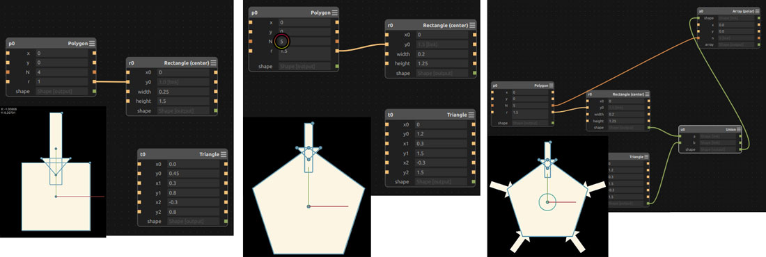
Add a CSG>>Union block and connect the green dots of rectangle and triangle to union's inputs (image above). Then add Array>>Polar array and connect it's green input to union's green output. Connect Poligon's number of corners N's output to array's last input. Then add a difference block and connect Union's and Polygon's outputs to difference's inputs. At this point you should get a ready model.
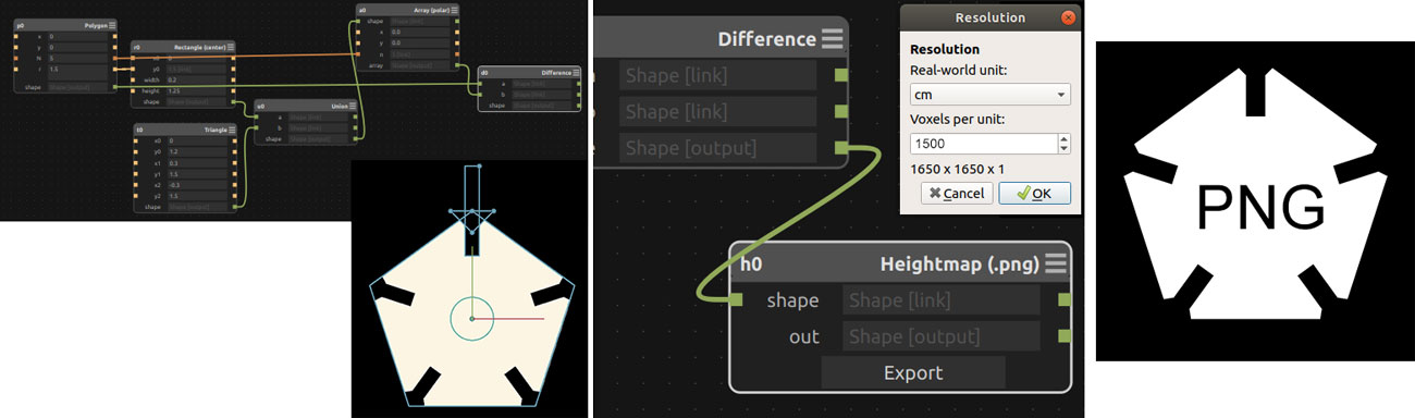
One big disagvantage of Antimony is that it only exports PNG and STL I would add SVG and OBJ too. So I added Export PNG block and connected Difference last output to Export's input, hit export. I used Corel Draw to trace png and layout the print ready file.
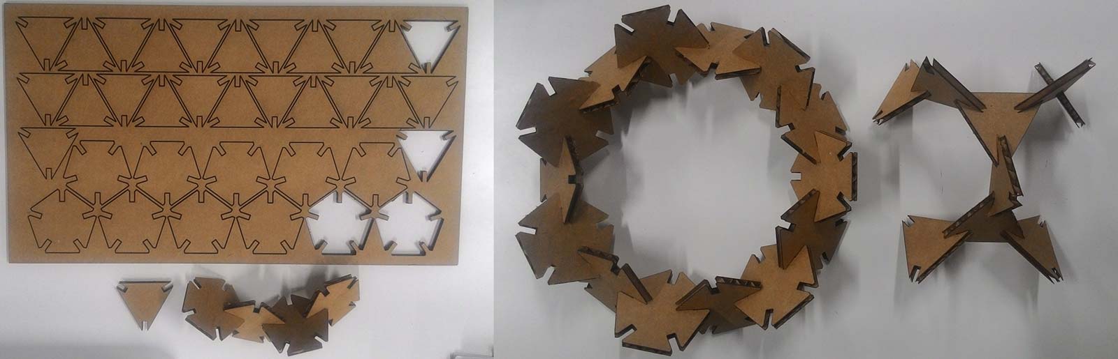
I was satisfied with the result but I would try to learn freecad more rather than using Antimony.
Here are the files:
rfid antenna.svg
gik_pentagon.sb (Antimony) and gik pentagon.png
gik_triangle.sb (Antimony) and gik triangle.png