Output Devices
For this week, I will use my own board designed based on the satcha kit, but until I have it ready, I will use an Arduino to develop the work.
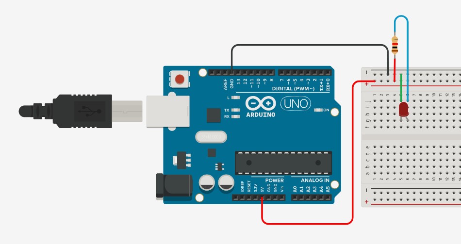
The simplest and most common output device is a led. When connected to 5v, the led will turn on. The resistor is used as a protection for the led. The Led have a polarity and the straight part is the negative and should always be connected to ground, if connected backwards, it will not work. The digital outputs on the Arduino can be controlled by code. Pins 0 to 13 can be controlled by code, so if instead of connecting the red jumper to 5v, you connect it to any of the GPIO, or general perpuse input/output, you can turn the led on or off by code just by declaring the pin as an output using the pinMode(PINNUMBER, OUTPUT); and changing the pinnumber for the correct pin. Then, using the digitalWrite(PINNUMBER, HIGH); or digitalWrite(PINNUMBER, LOW); you can turn it on or off.
Stepper Motor’s.
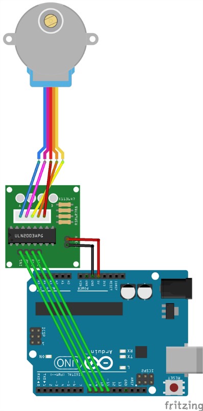
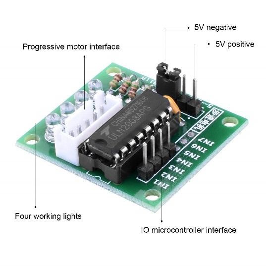
A stepper motor consume high current and hence a driver IC like the ULN2003 is mandatory. To understand how to make this motor rotate we should look into the coil diagram below.
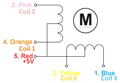
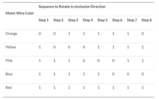
As you can see there are four coils in the motor. One end of each coil is connected to +5V (Red) and the other ends (Orange, Pink, Yellow and Blue) are taken out as wires. The Red wire is always provided with a constant +5V supply and this +5V will energize the coil only if the other end of the coil is connected to ground. A stepper motor can rotate only if the coils are energized (grounded) in a logical sequence. This logical sequence can be programmed using a microcontroller or by designing a digital circuit. The sequence in which each coil should be triggered is shown in the table below. Here “1” represent the coil is held at +5V, since both the ends of coil is at +5V (red and other end) the coil will not be energized. Similarly “0” represents the coil is held to ground, now one end will be +5V and the other one is grounded so the coil will be energized.
In order the make the motor rotate, I will first learn how to create a manual code to energize each coil and make it move, and then, I will use a library to do the same using much less code. Notice that the driver must have the 5v jumper in order to work connected directly to the arduino. Otherwise, you must connect it to a 12v source.
// Define the pin where the coils are conected
#define IN1 8
#define IN2 9
#define IN3 10
#define IN4 11

// Step sequence(max torque)
int step [4][4] =
{
{1, 1, 0, 0},
{0, 1, 1, 0},
{0, 0, 1, 1},
{1, 0, 0, 1}
};

void setup()
{
// Define all pins as outputs
pinMode(IN1, OUTPUT);
pinMode(IN2, OUTPUT);
pinMode(IN3, OUTPUT);
pinMode(IN4, OUTPUT);
}


void loop()
{
for (int i = 0; i < 4; i++)
{
digitalWrite(IN1, step[i][0]);
digitalWrite(IN2, step[i][1]);
digitalWrite(IN3, step[i][2]);
digitalWrite(IN4, step[i][3]);
delay(10);
}
For the manual sequence, I need to create a vector matrix with 1 and 0s for the sequence. After defining the ports as outputs, I just need to create a for structure to go around the array and turn the correct coil on.
Even though is how it works, I can use a library to make it easier. By includding the The Stepper.h library which is included in the arduino IDE, you just need to determine the number of steps, and then use the stepper command using the steps, and the pins where the motor is connected as arguments. Finnaly, just set the speed, and the use the step command and set the number of steps you want for the motor to move.
test
// Include the Stepper library
#include

// Define the number of steps in one minute
#define STEPS 4096
// Number of steps
#define NUMSTEPS 100

// Constructor, must include STEPS and the pins where the coils are connected
Stepper stepper(STEPS, 8, 9, 10, 11);

void setup() {
// Determine the speed in RPM
stepper.setSpeed(5);
}

void loop() {
// Move the motor the number of steps required
stepper.step(NUMSTEPS);
delay(2000);
}
Note that this code is much simpler, and to control the speed, you must only change one line.
Now, lets try a DC motor. This motors usually require more energy than the Arduino can handle, and because of this, an external power source is suggested.
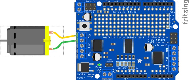
To control them, we need a driver, and in this case, I will use the adafruit motor shield which I have available. After connecting my motor, we can test with the example code:
/* This is a test sketch for the Adafruit assembled Motor Shield for Arduino v2 It won't work with v1.x motor shields! Only for the v2's with built in PWM control For use with the Adafruit Motor Shield v2 ----> http://www.adafruit.com/products/1438 */ #include#include // Create the motor shield object with the default I2C address Adafruit_MotorShield AFMS = Adafruit_MotorShield(); // Or, create it with a different I2C address (say for stacking) // Adafruit_MotorShield AFMS = Adafruit_MotorShield(0x61); // Select which 'port' M1, M2, M3 or M4. In this case, M1 Adafruit_DCMotor *myMotor = AFMS.getMotor(1); // You can also make another motor on port M2 //Adafruit_DCMotor *myOtherMotor = AFMS.getMotor(2); void setup() { Serial.begin(9600); // set up Serial library at 9600 bps Serial.println("Adafruit Motorshield v2 - DC Motor test!"); AFMS.begin(); // create with the default frequency 1.6KHz //AFMS.begin(1000); // OR with a different frequency, say 1KHz // Set the speed to start, from 0 (off) to 255 (max speed) myMotor->setSpeed(150); myMotor->run(FORWARD); // turn on motor myMotor->run(RELEASE); } void loop() { uint8_t i; Serial.print("tick"); myMotor->run(FORWARD); for (i=0; i<255; i++) { myMotor->setSpeed(i); delay(10); } for (i=255; i!=0; i--) { myMotor->setSpeed(i); delay(10); } Serial.print("tock"); myMotor->run(BACKWARD); for (i=0; i<255; i++) { myMotor->setSpeed(i); delay(10); } for (i=255; i!=0; i--) { myMotor->setSpeed(i); delay(10); } Serial.print("tech"); myMotor->run(RELEASE); delay(1000); }
The motor can be controlled using the run method, and the argument can be FORWARD, REVERSE, or RELEASE. setSpeed controls speed and requires an input from 0 to 255 and AFMS.getMotor(n) specifies which motor, and n should 1,2,3 or 4 depending on where is the motor connected.
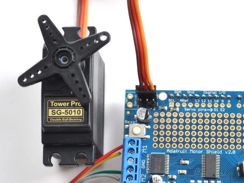
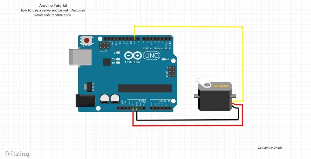
Now lets try a servo motor. Servo motors are very simple to use and are a great choice when you need to control position. Simply connect them either using the shield, or directly to the Arduino
Using this code, we can control the servo,
 #include
Servo servo;
int angle = 10;

void setup() {
servo.attach(8);
servo.write(angle);
}

void loop()
{
// scan from 0 to 180 degrees
for(angle = 10; angle < 180; angle++)
{
servo.write(angle);
delay(15);
}
// now scan back from 180 to 0 degrees
for(angle = 180; angle > 10; angle--)
{
servo.write(angle);
delay(15);
}
}
Notice that is your servo is connected to pin 8, in servoMotor.attach(x); X should be the pin you have it connected to. This is a very simple code that makes the servo move 180 degress, in 10 degree intervals, with 15ms delay between each movement. Just by using the servo.write(angle) commande, you can control it.
This week I explored several output methods, which I hope will help me develop my project in the end. I learned a lot as it’s the first time for me using this many electornic components.
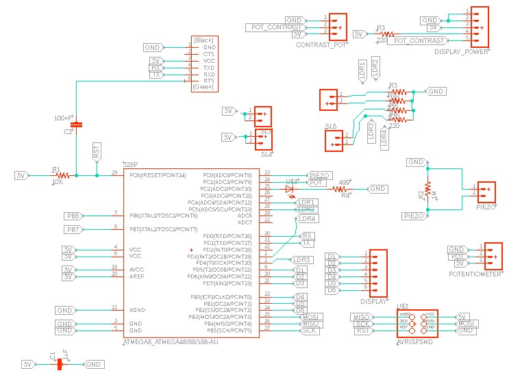
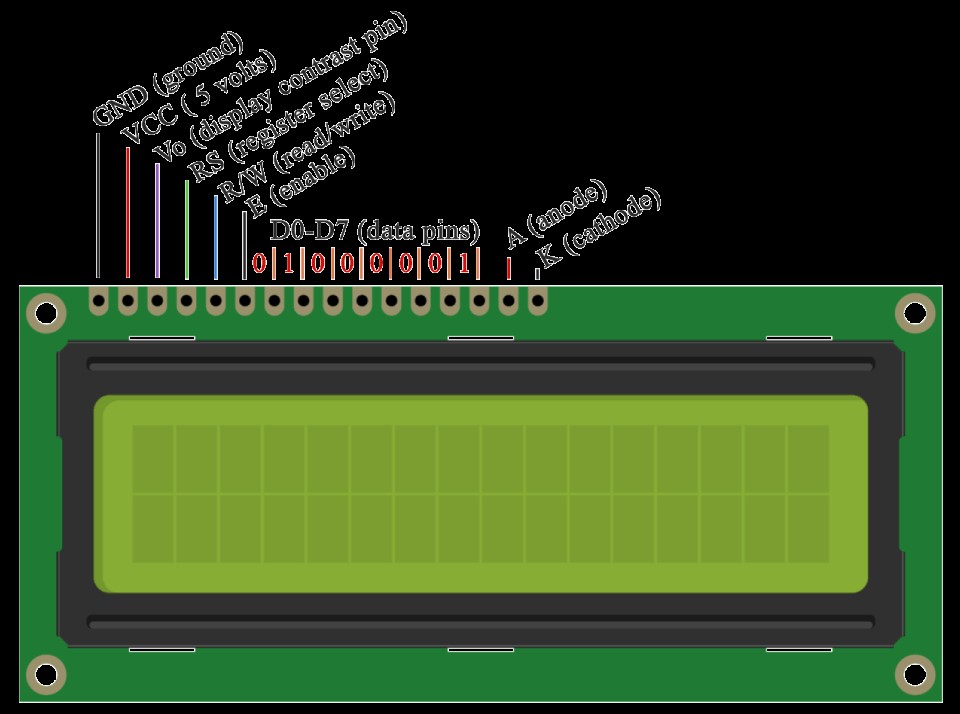
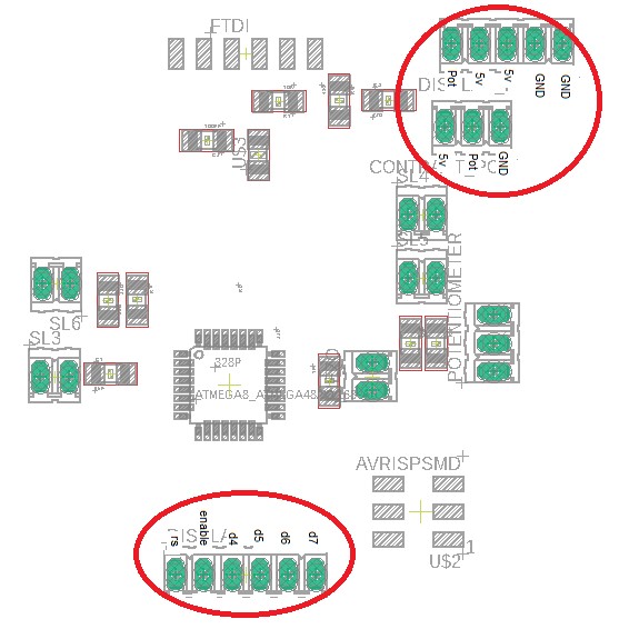
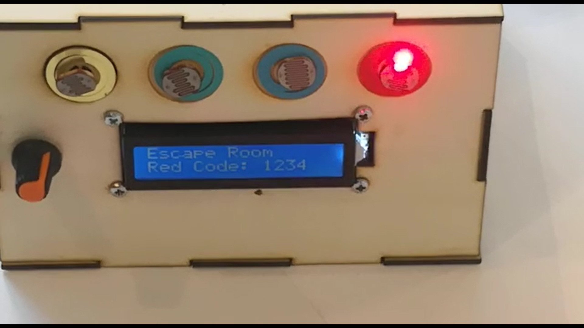
Here, the component used as output are the 16x2 LCD screen. As seen in the following schematic, we need a ground, vcc, potentiometer, and 6 digital outputs.
\
- For this the following components in our board will be used
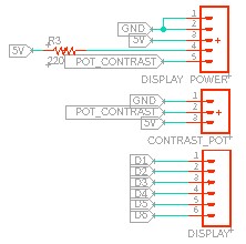
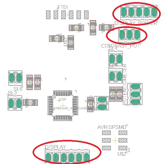
- connected in the following pins:
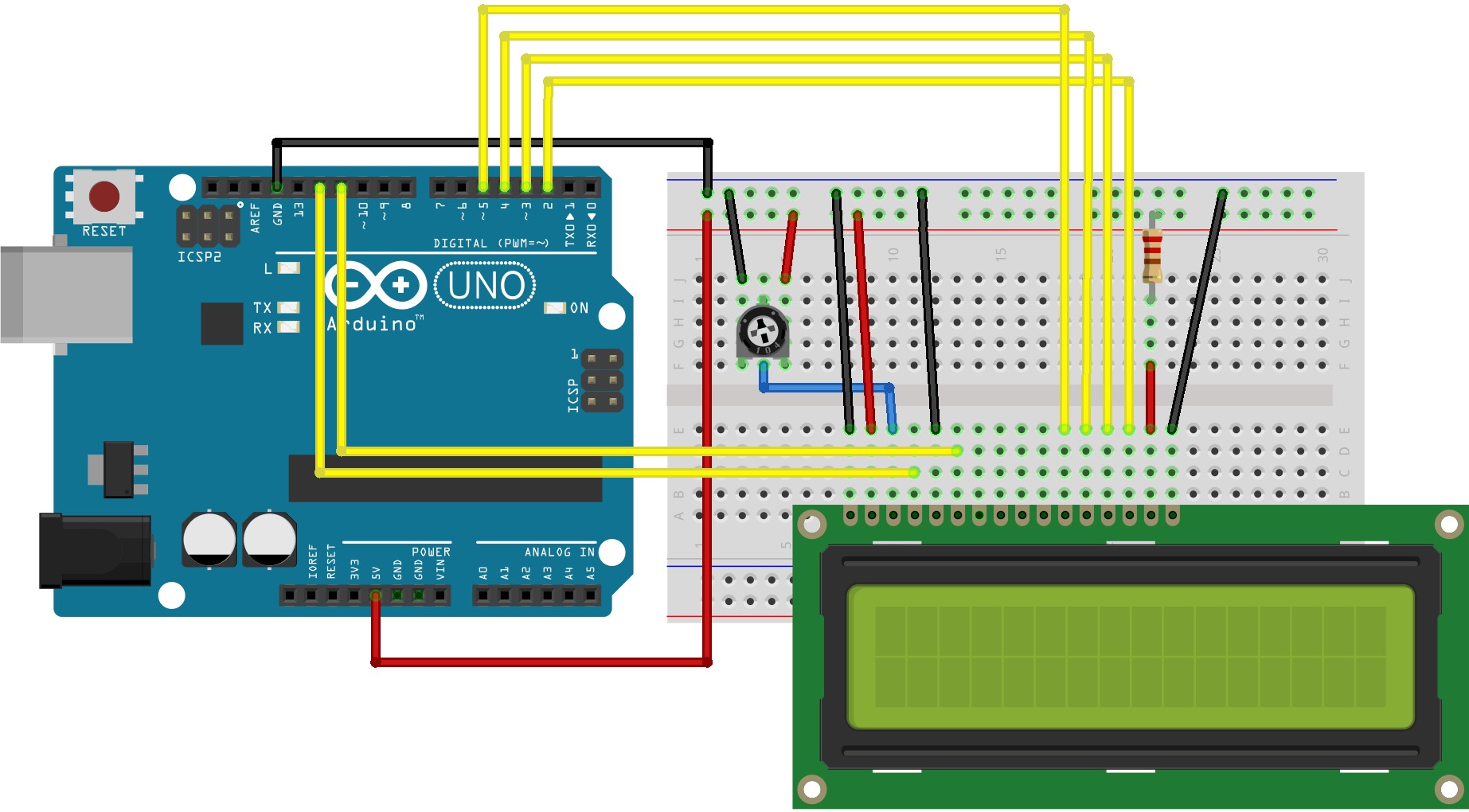
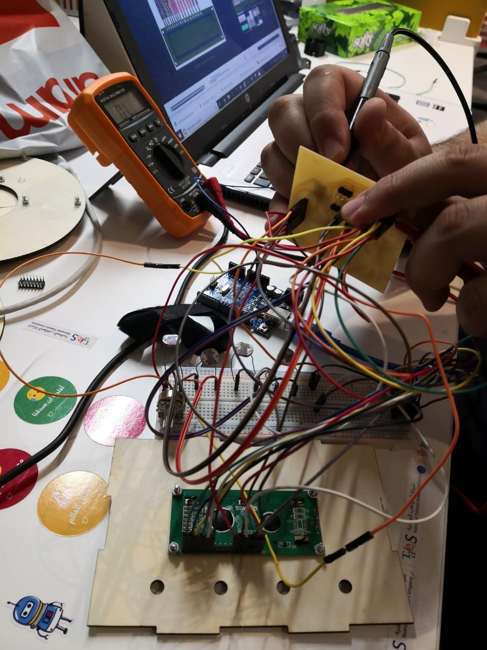
- To test, I used a protoboard and jumpers to connect all
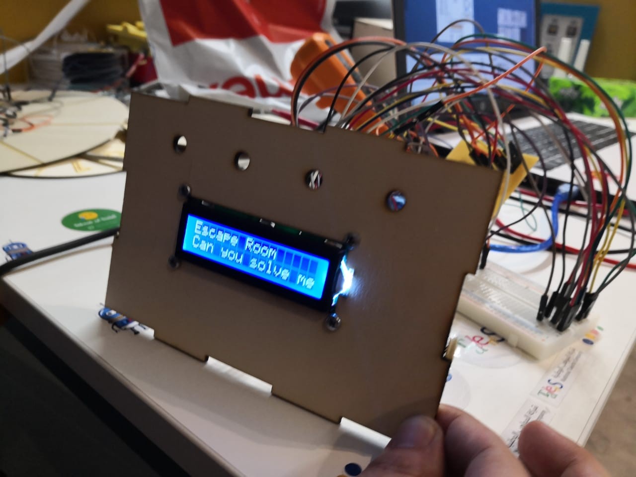
- And finally, After connected and powered, I was able to see the output!
 \
\
The code is very simple, I start by including the library with the line
#include <LiquidCrystal.h>
Then, I define the variables that I will use,
const int rs = 5, en = 6, d4 = 7, d5 = 8, d6 = 9, d7 = 10;
and use the liquid crystal method with the variables of the data pins used.
LiquidCrystal lcd(rs, en, d4, d5, d6, d7);
In the Setup Loop, I initialize the LCD with the lcd.begin method and define its 16 columns and 2 rows, and the print a first message using the lcd.print method, and then just send what you want to print as a string using “”.
						  // set up the LCD's number of columns and rows:
lcd.begin(16, 2);
// Print a message to the LCD.
lcd.print("Escape Room");
Then, depending on the logic explained in the input week, I will display a code depending on which LDR is being iluminated by the laser. For this, I just add an lcd.setCursos method and place it in the first column of the row 1, and then and lcd.print with the message I want to print. If no LDR is being iluminated, I just display a message saying, “Can you solve me”
							if (ldr1 > 200) {
lcd.setCursor(0, 1);
lcd.print("Red Code: 1234 ");
} else {
if (ldr2 > 200) {
lcd.setCursor(0, 1);
lcd.print("Blue Code: 1234 ");
} else {
if (ldr3==HIGH) {
lcd.setCursor(0, 1);
lcd.print("Green Code: 1234 ");
} else {
if (ldr4==HIGH) {
lcd.setCursor(0, 1);
lcd.print("Yellow Code:1234 ");
} else {
lcd.setCursor(0, 1);
lcd.print("Can you solve me?");
}
The complete code can be found here: Download File: the LDR code
and as shown in the final project page, it was working correctly for both analogue and digital inputs.
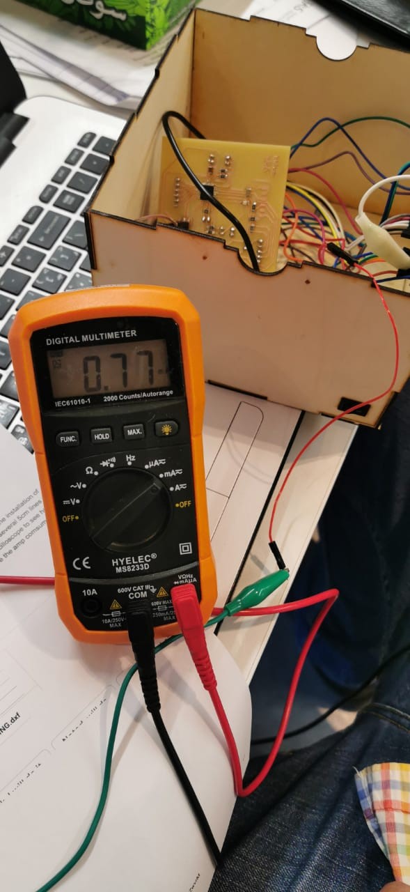
To characterize my output device, I used a multimeter and open the power line going to the LCD and connected a multimeter to measure the amp consumption.
When checking the datasheet, it shows that it should draw from 1.2 to 3 mA.
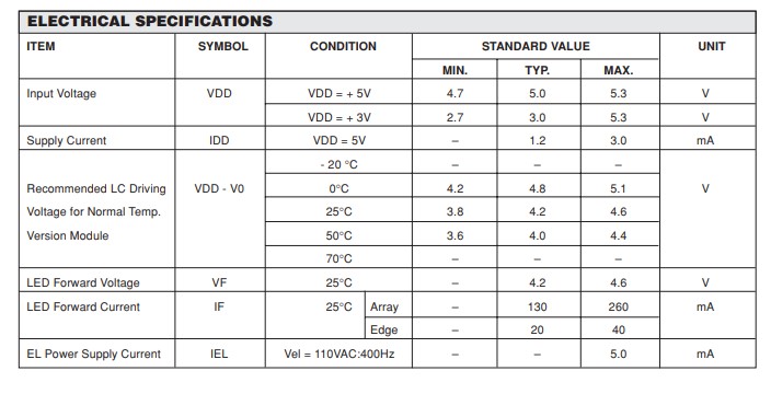
When measuring, it shows that it uses around 0.77 mA, which means that its using less power than its supposed, possible because its all powered from a batery and not a strong power source.
LCD Test
As our global evaluator said we cannot use the same board as our final project, I created a new board only for input and output.
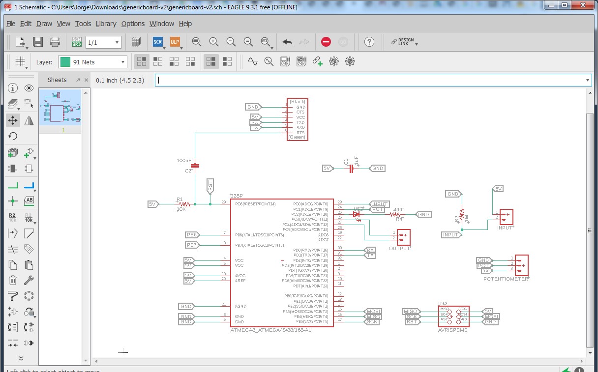
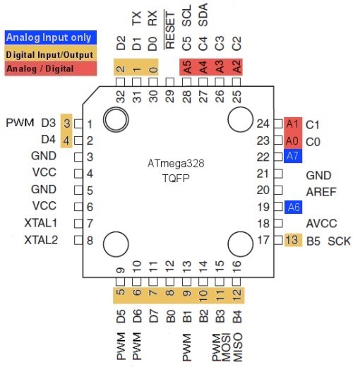
In this board, I will connect my servo as an output, using the pin 24, which is the A1 as seen on the atmega pinout.
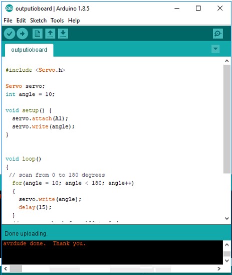
Using this code, we can control the servo,
#include <Servo.h>
Servo servo;
int angle = 10;
void setup() {
servo.attach(A1);
servo.write(angle);
}
void loop()
{
// scan from 0 to 180 degrees
for(angle = 10; angle < 180; angle++)
{
servo.write(angle);
delay(15);
}
// now scan back from 180 to 0 degrees
for(angle = 180; angle > 10; angle--)
{
servo.write(angle);
delay(15);
}
}
This is a very simple code that makes the servo move 180 degress, in 10 degree intervals, with 15ms delay between each movement.
Just by using the servo.write(angle) command, you can control it. All the
connections needed are ground and vcc, and the pin for the servo.
I download it to my board using an arduino as a programmer,
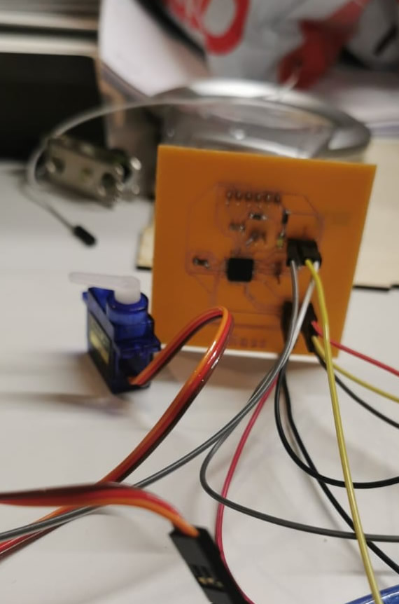
Here you can see my connection to the board created only for input and output
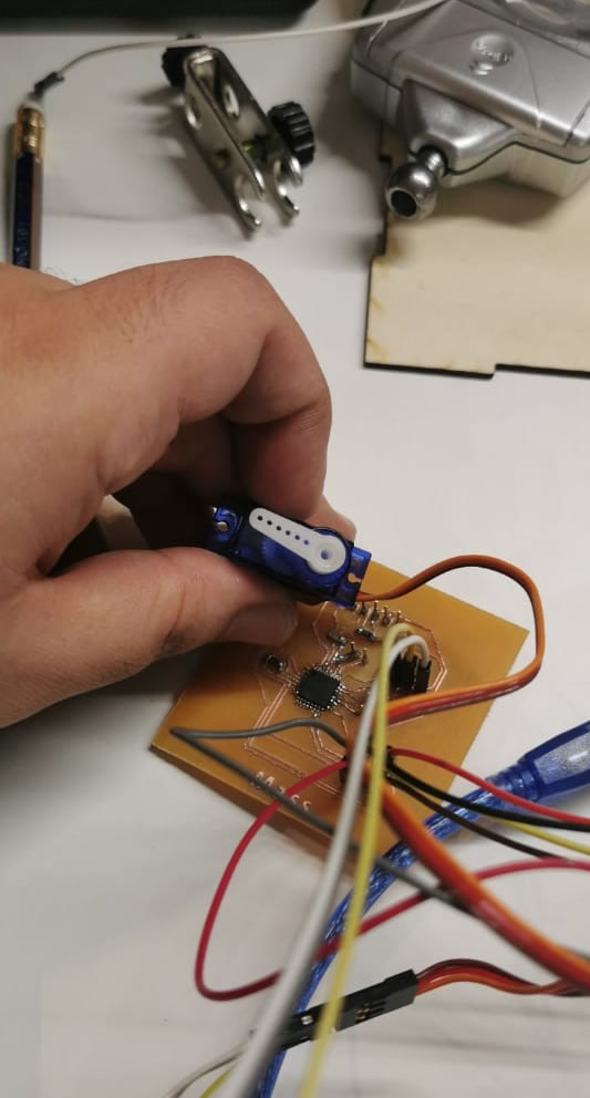
and here a result of the servo moving:
ADD VIDEO OF SERVO MOVING
Download File: output code
Download File: Input&output code
Download File: ioboard.sch
Download File: ioboard.svg
Download File: the eagle bored Design