Computer-Aided Design.
For this week the first steps of the final project are carried out. A 3D model of my first sketch made in the first week will be created.
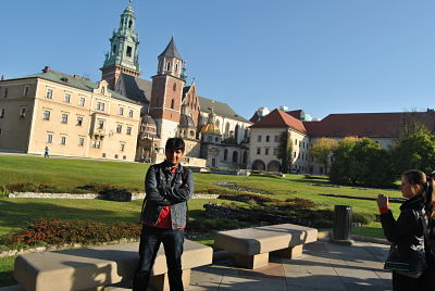
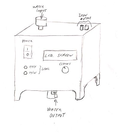
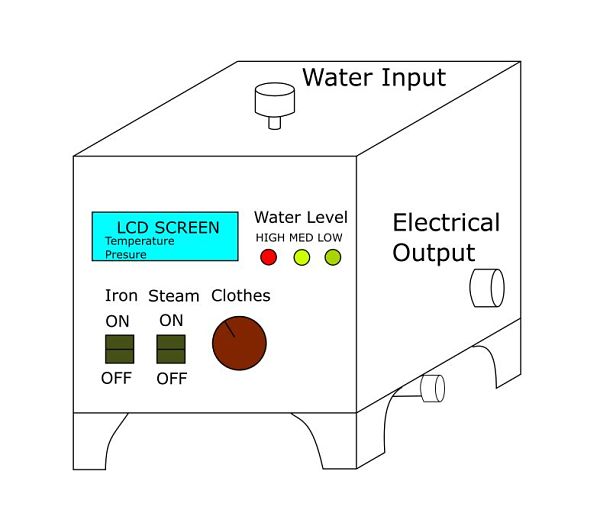
To achieve this, a 2D model of the sketch is made to finish in a 3D model. The first sketch is seen in the following picture:
Raster vs Vector
For the creation of a digital 2D sketch, we must know the difference between a raster and an image vector.Raster
According to the Cambridge dictionary:a type of computer image that is based on a rectangular grid of pixelsWhen talking about raster images, we can quickly make things very complicated by talking about pixels and resolutions.
Vector
According to the Cambridge dictionary:something physical such as a force that has size and directionVector graphics, on the other hand, are made up of shapes created by awesome math functions that allow them to scale infinitely.
You can read more about raster or vector Here.
2D Software
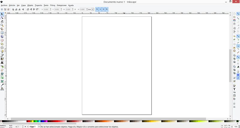
The first step that must be taken to make a 2D drawing by computer is the choice of software. With regard to this first part I know that there are very powerful software, such as the Illustrator and Photoshop , but I decide to choose only free software for this part. The main reason is the use licenses, since they can be very expensive.To make a 2D drawing, I downloaded two open source software: Inkscape (vector) and GIMP (raster). The first one I used was GIMP, since I had thought of using it to resize images, but I found a web page that does that work without installing software.
I went back to using the GIMP software with the help of web tutorials, but I did not feel very comfortable with the software interface, since it is more focused for more complex drawing designs than I have thought. Another reason why I discard the software is because for my idea I do not need a raster image, with what I will definitely use Inkscape.
Inkscape
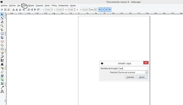
 It is time to draw! to have an order, I decided to create the drawing by layers.
The first layer will be the case, the second the details, then the layer of the inlets and outlets of the plate and finally the layer of the relief valve.
It is time to draw! to have an order, I decided to create the drawing by layers.
The first layer will be the case, the second the details, then the layer of the inlets and outlets of the plate and finally the layer of the relief valve.In the menu, we look for the layer option and create a layer, the first being the case, as seen in the picture.
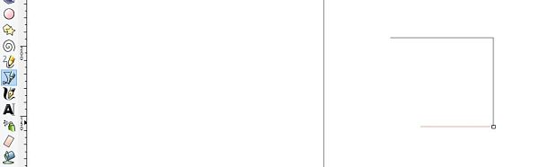
I use the tool to draw lines and draw the whole case.
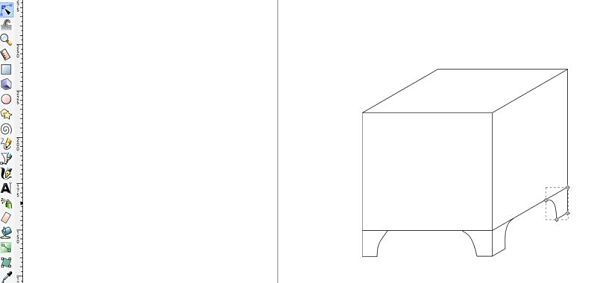
To give a curve to the lines, double click on a line and deform the drawing, as seen in the picture.
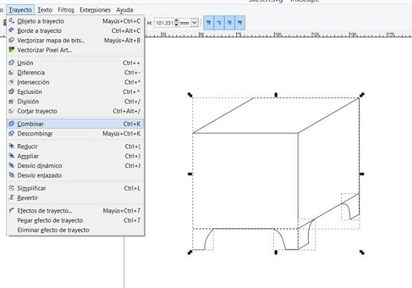
At the end of all the lines, a combination of the drawing 2d is made to be able to have it as a single block, in the picture it is appreciated how to make a combination of the drawing.
Once the layer of the case is made, we proceed to the details layer, in this case we use colors to differentiate the parts, besides placing text that will be useful in our project. In the picture you can see the layer of details.
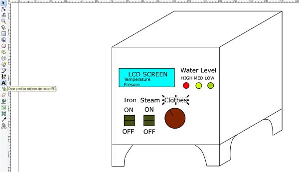
The final 2d sketch has this aspect, where the words water input and electric output, is only for reference, it should not appear in the final project.
3D Model
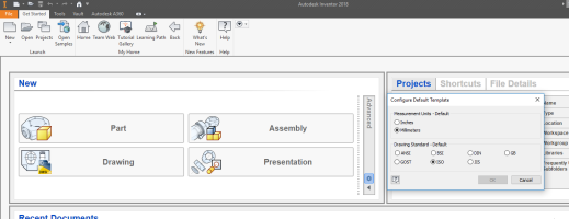
To make my 3D model now I will use the software: Inventor 2018. I have an experience of using more than 5 years in the use of the software, while with the software Solidworks I have less years of experience. Another reason is the agreement that exists between the university and Autodesk for licenses. I plan later to start using the software Fusion360, but this week I will only use Autodesk Inventor.To begin with the 3D design, I first made sure to configure the software in a way. In my case I always work in the ISO format and in millimeters, as shown in the Picture.
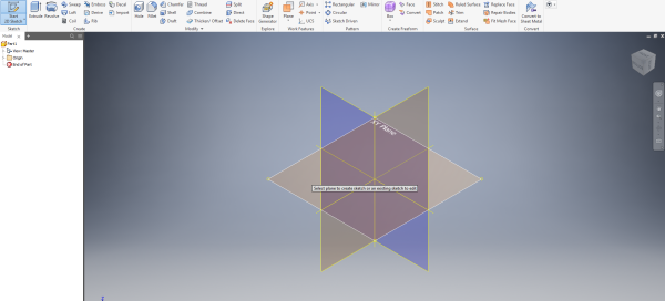
 It is time to create a new part! The XY plane is selected as seen in the picture to start with the sketch.
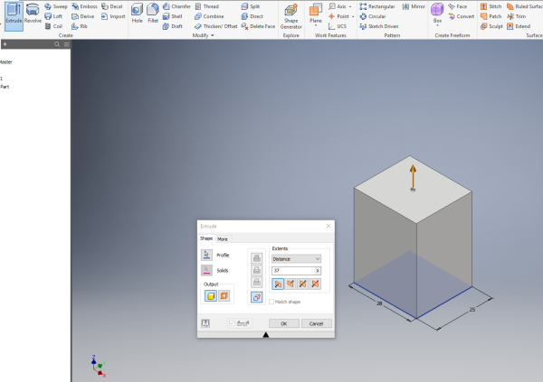
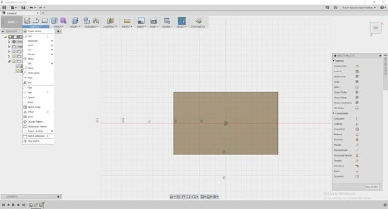
 Draw a square with the measurements that our drawing will have, I use the rectangle option with the center and corner reference points, using the center as the center of the coordinates.
In this case I'm drawing it at a 1:10 scale so I can work in a more accelerated way.
Draw a square with the measurements that our drawing will have, I use the rectangle option with the center and corner reference points, using the center as the center of the coordinates.
In this case I'm drawing it at a 1:10 scale so I can work in a more accelerated way.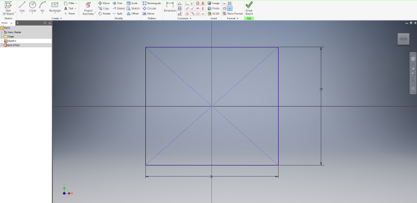 After drawing the square, an extrusion is done, that means that we give a volume to a certain size, as shown in the picture.
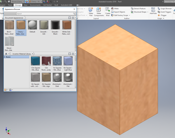
 What is sought in this task is the correct use of the software, that is why a texture and color is added to the model of the case.
The idea of the project is to make the case of medium density fiberboard, so I choose a wood look and a similar color, resulting in the picture.
What is sought in this task is the correct use of the software, that is why a texture and color is added to the model of the case.
The idea of the project is to make the case of medium density fiberboard, so I choose a wood look and a similar color, resulting in the picture.
 Then we can see some images of how it was added some details of the project, such as buttons, LEDs, lcd, etc.
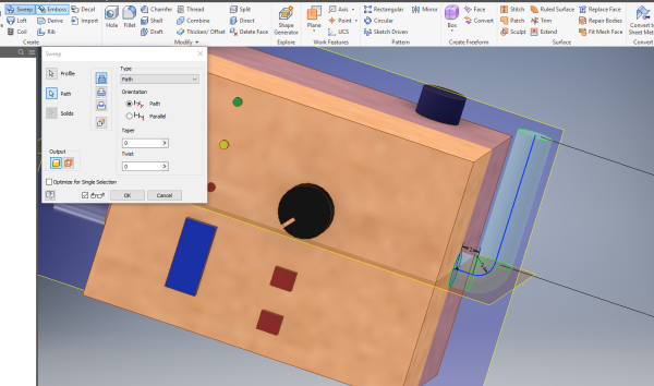
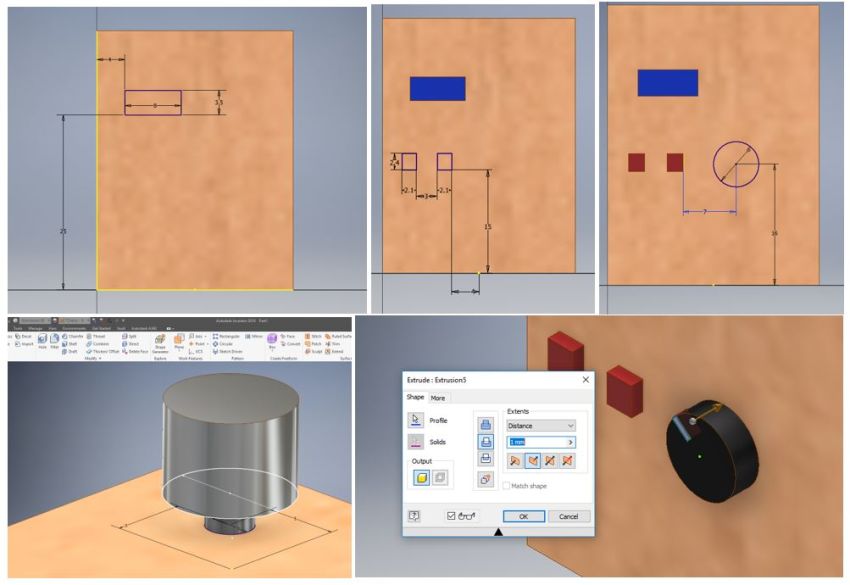 To include the pipe where the drainage is made, draw a circle in the center of the base and visualize the cutting planes to be able to use the Sweep tool, a line will be created perpendicular to the circumference and with tangency restrictions, as appreciates in the picture.
 Finally, the base drawing and the rail that will follow are selected to obtain the following picture.
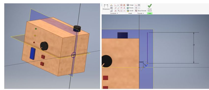
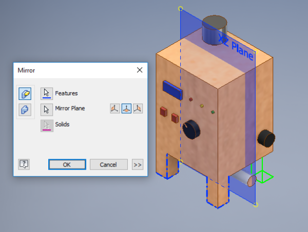
 The supports are created, for them we only draw two and with the mirror tool we create the other two, for this we need a parallel and centered plane, as they are shown in the picture.
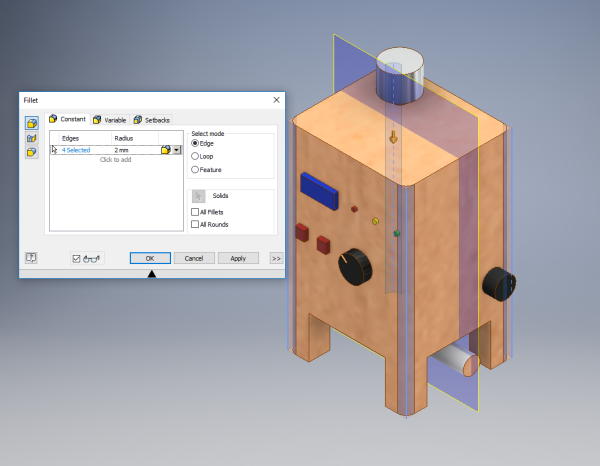
 The edges are softened using the fillet tool, to get a little aesthetics with the drawing.
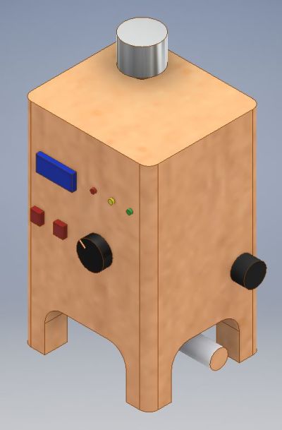
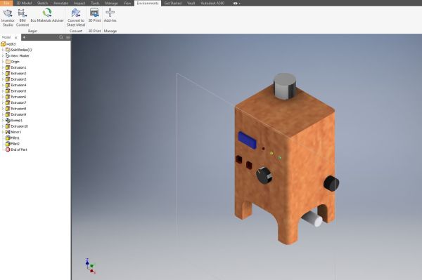
 Finally you can see the final 3d Drawing.
Render
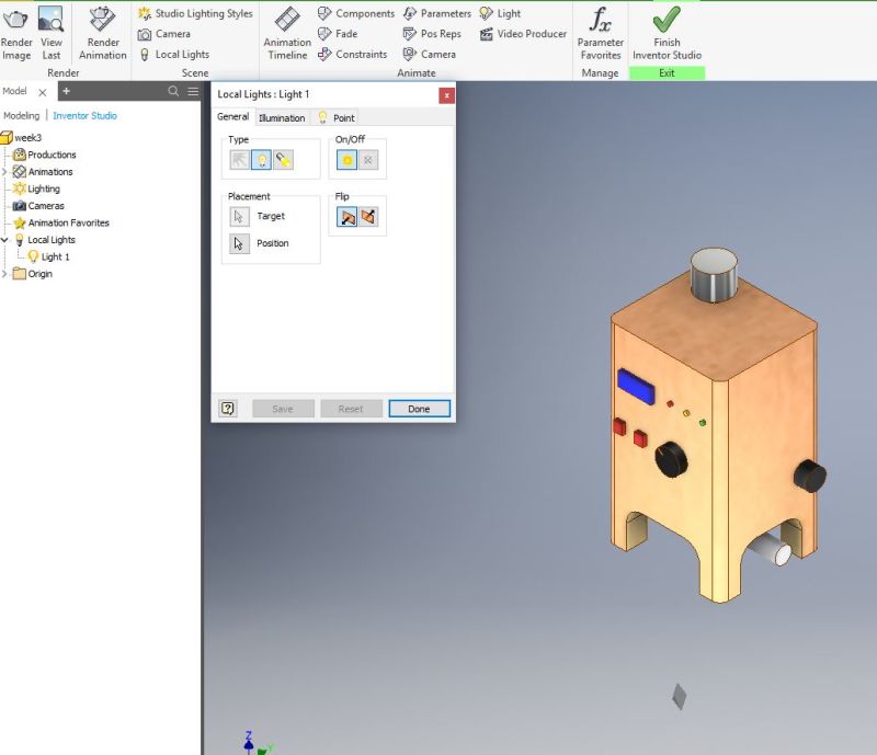
Rendering is the process involved in the generation of a two-dimensional or three-dimensional image from a model by means of application programs. Rendering is mostly used in architectural designs, video games, and animated movies, simulators, TV special effects and design visualization. The techniques and features used vary according to the project. Rendering helps increase efficiency and reduce cost in design.To perform the rendering in inventor, we must go to the environments section and initialize the inventor Studio, as shown in the picture.
 After performing several tests, which are explained below, we decided to place a light and the configuration of the rendering as shown in the picture.
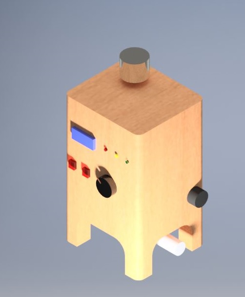
 Now, it is time to see the final render
Additional comments
2D Model
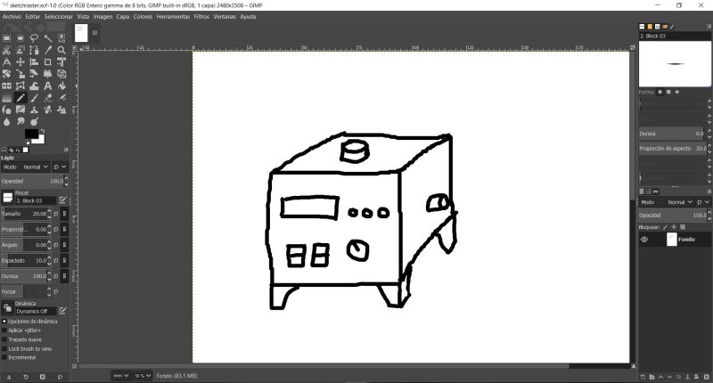
As I mentioned earlier in 2D drawing, I used the GIMP software to make a 2D sketch.It is a software of the Raster type, that means that it works by pixels. One of the biggest difficulties of working with this software is to design with a mouse what makes the work too difficult. We can see in the picture the software and the visualization of the pixels. I will mention again that for my design I prefer drawing using vector.
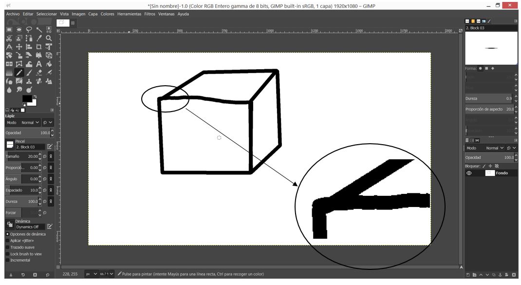 Here my raster design.
Desing and files
In order to create 3D designs, the first step is to draw 2D sketches using simple commands such as lines, polygons, circles, etc. There should only be one main restriction: There should be no open sections in the design, everything must be closed contours.To be able to visualize a design in other software other than the one used in the creation of the same, it is recommended to use the extension .obj or .stl.
These files can be displayed in several software but as a single piece, some software has the possibility of transforming the imported file into one of the design software.
3D Model
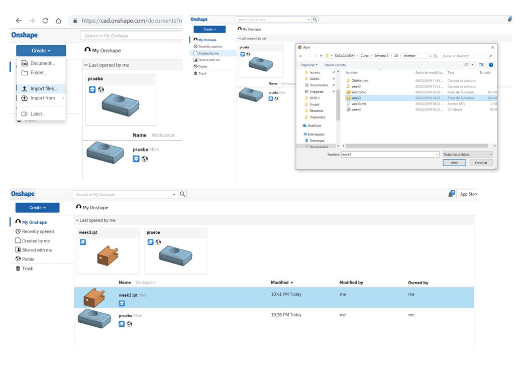
As I mentioned before, I have experience with the Inventor software, but I decided to try the antimony, but I use the Windows operating system, so I could not execute it. The following software that I used was the onshape and I was able to make a small drawing.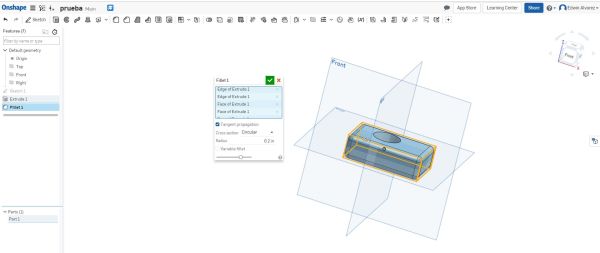 Using the Onshape software you can see slight differences between the Inventor software and this one. A significant difference is the modification of the color and the material of the created design, besides not being able to get the rendering.
The creation process of the 2D and 3D drafts are really similar to the Inventor for example we can also create restrictions such as dimensions, tangencies, etc. for the 2D design, but only you can use inches not millimeters.
You can even import inventor files to the Onshape and this converts it to continue with the design in case the Inventor is not installed.
 Another software that I used is the Solidworks, since in my work I use it to make tests of efforts, since my project is an industrial application, I realized that the potential of the software is wasted.
Render
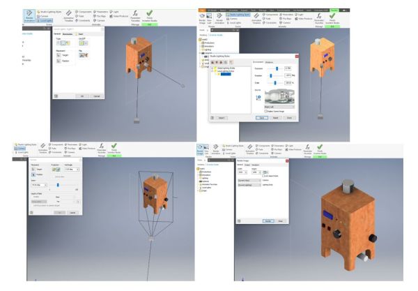
In the rendering, at the beginning I left all the values by default, obtaining the next picture.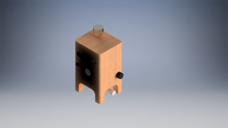 That is why I started to modify several parameters, such as the location of the camera, the light and the type of light.
You can observe the different configurations that I used until obtaining the result that was seen previously.
That is why I started to modify several parameters, such as the location of the camera, the light and the type of light.
You can observe the different configurations that I used until obtaining the result that was seen previously.
Fusion360
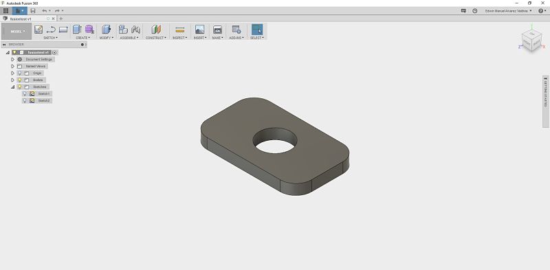
In order to have more knowledge of software, I use Autodesk Fusion360 taking into account that all the files will be saved in the cloud and the files should be exported if you want to work on another computer without using your own username and password. Being of Autodesk, it is very similar to the inventor, only that this software has a smaller work menu, as well as letters of direct access to certain tools such as the letter D for Dimension.
 To make volume or cut extrusions, we only must place the measurement with positive or negative values to be able to achieve our final design.
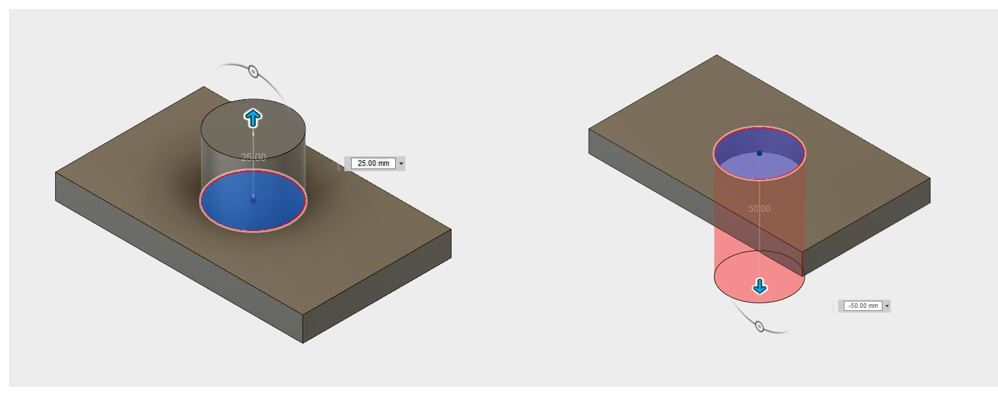 This software is more compact than the Inventor software, it also has the option to create the machining in a milling machine or a lathe, although this tool will not be used at the moment.
Here is an image of the software test.
Download Files
You can download this files Here:Inventor.
Inkscape.
GIMP design.
Onshape.
Fusion360 design.