
Output devices.
For the assignment of the 12th week: Outputs devices, it will be divided into 6 parts: Output devices, board, programming, problems, group and Download.
Output devices
In this week we started working with outputs, these devices make a change of a variable that we are measuring by different sensors.In the laboratory we have several types of devices that work as outputs, both analog and digital, here is a list of the components we have available:
| Name | Type | Fuction |
|---|---|---|
| LED | Digital. | Led of different colors. |
| LED RGB | Digital. | Red, green and blue led. |
| SPEAKER | Analogic. | Speaker. |
| Button | Digital. | Button. |
| JGA25-371 | Analogic. | DC Motor with encoder. |
| LCD16x2 | Digital. | LCD display. |
| HK15178 | Analogic. | 1.4Kg Servomotor. |
| CS-939MG | Analogic. | 2.5Kg Servomotor. |
| 35BY48L030-01 | Analogic | Stepper motor. |
The RGB LED will indicate when the steam machine is in the heating process (red LED), it is ready to work (green LED) and when the output valve is active (green LED), for the simulation of the valve I will use the CS-939MG servomotor
Board
As I will use two outputs, I will use the attiny44 to have more pins output and inputs, for both cases I will use the PWM for the 4 outputs: 3 for the RGB led and one for the servomotor.A Pulse Width Modulation (PWM) Signal is a method for generating an analog signal using a digital source, this technique is widely used to control the brightness of a LED, the speed of a motor, the angle of rotation of a servomotor, etc.
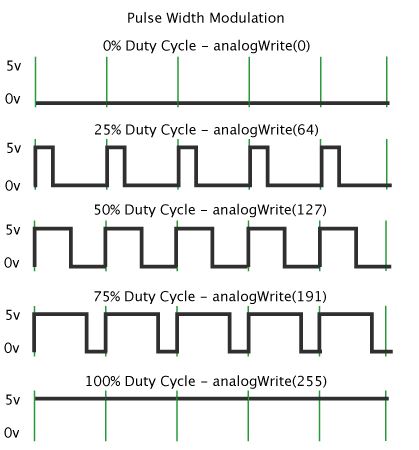
Source: https://www.arduino.cc/en/tutorial/PWM
The attiny44 use the following pin for PWM: PB2, PA7, PA6 and PA5. For the RGB led I used these pines: PB2, PA8 and PA6, in the case of servomotor, I use the PA5 pin.In the attiny44 data sheets, especially on the page 175 , the maximum amperage of 60mA.
Reading the data sheets of the output devices we have the following information about amperage:
| LED RGB R: 50-20mA G: 25-100A B: 25-100A |
Datasheet of RGB |
| Servomotor 200-240mA |
Datasheet of Servomotor |
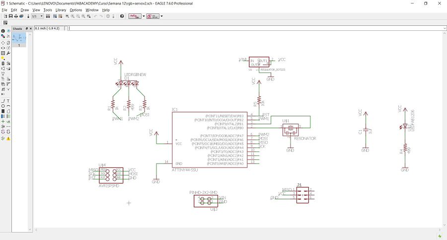
Based on the designs of the assignment, I make my own schematic design of my output board, as shown in the picture.
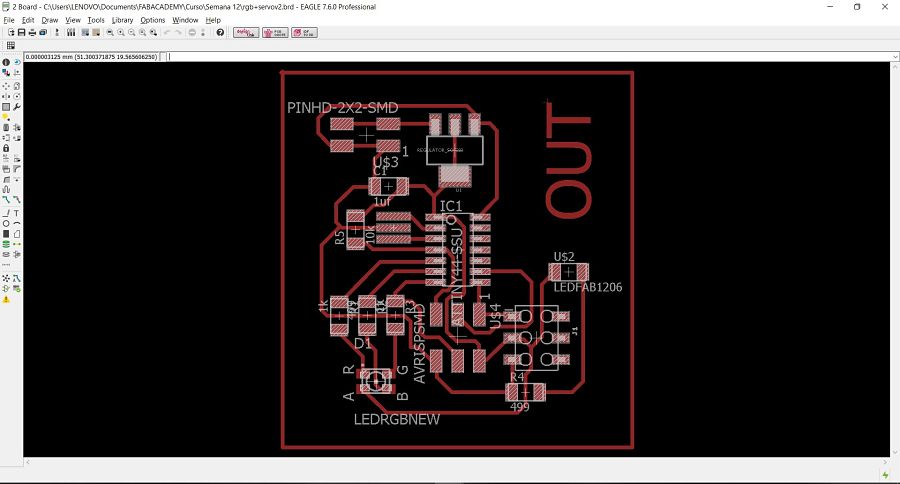
 And here is the board.
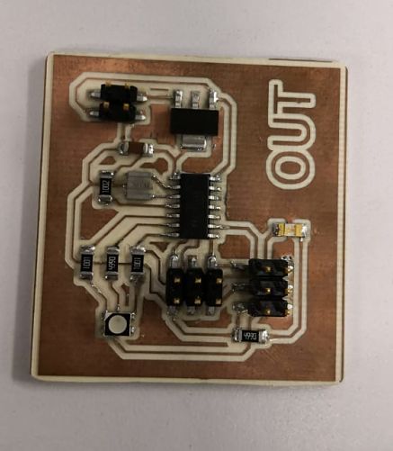
 Here is the manufacturing board.
Programming
The difference of the previous weeks, we only use the ISP to program the board, that is because there is a voltage regulator that can cause interference with the power supply of the FTDI, the final wiring is the one seen in the picture.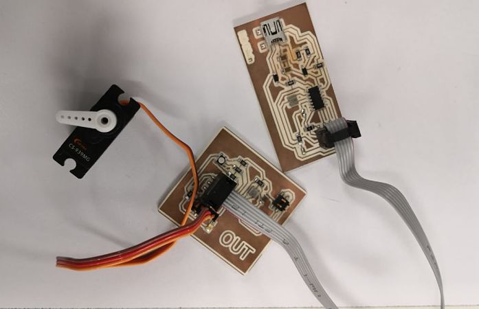
LED RGB
I start to program the LED with a simple ignition of the three leds. The ignition code is the following: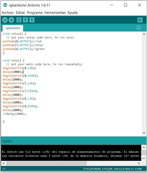 The next code is the turning on of the RGB using the PWM, turning on the red led first, then the blue and finally the green one.
The code used is the following
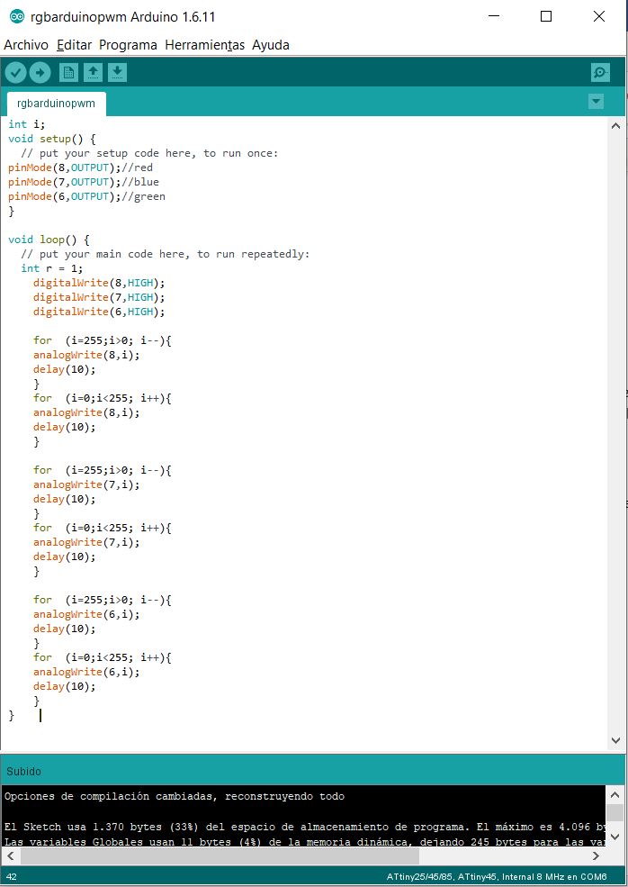
The next code is the turning on of the RGB using the PWM, turning on the red led first, then the blue and finally the green one.
The code used is the following
 You can see a video of the functioning of the on and off of the LEDs, as well as the operation of the PWM
Servomotor
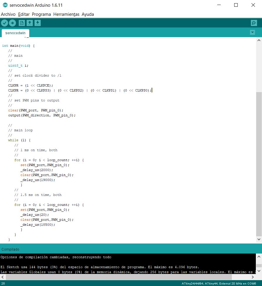
For the servomotor operation, I use a very basic code that works with an Arduino, the code is shown in the following picture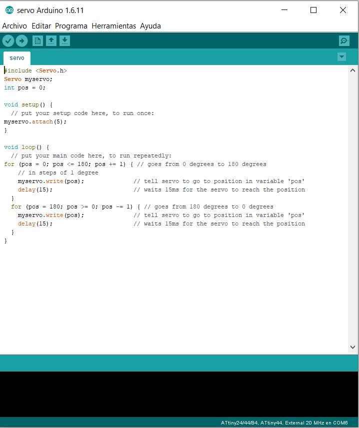 As with the softwareserial library, the servo library does not work correctly, so it is decided to program in C, for this I modify the code provided by Neil , my final code being the following:
 In the following gif we can see the movement of servomotor.
Integration
For the integration of servomotor and RGB, I make a small application of what would be the logic of my final project:The Red LED will light up until the water reaches its desired temperature, when it reaches that value, the green LED will light be indicating that the system is ready. When the valve is activated, which will be the servomotor, a blue LED will light be indicating that it is in operation.
Here is a gif of the final operation.
Problems
As we have problems with the arduino language, we tried to carry out a C programming with the simple ignition of the LEDs, having the following code and its demonstration in a gif.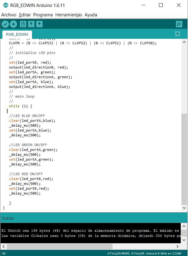
Group
The group work this week, asks us to measure the consumptions of the board, for this case we have used the basic example of a led RGB of Neil and the output devices board of our partner Italo. The contribution on my part was to measure the amperage consumption values, for this the ON / OFF programming of the RGB LEDs is upload to the board.
 Since we can not measure current intensity directly, we will use the formula of Ohm's law:
 V = IxR.The real values of the resistances are the following:
| Nominal Value | Real Valuel |
| Red Resistor: 1 kΩ | 0.998 Ω |
| Green Resistor: 1 kΩ | 0.998 Ω |
| Blue Resistor: 499 Ω | 498.6 Ω |
| Red Voltage | 3.120 V |
| Green Voltage | 3.120 V |
| Blue Voltage | 2.244 V |
| Red Current | 3.12 mA |
| Green Current | 3.12 mA |
| Blue Current | 4.5 mA |
Download files
You can download files Here:Code
Integration code
RGB Arduino
RGB PWM Arduino
Servo Arduino
Servo C
RGB C
Board
Schematic design
Board design
Manufacturing
Traces
Out
Gropu Code in C
On / Off code
PWM code