15. Mechanical design
This was a pretty fun week for me. We only had a group assignment, and that was to make a machine. We had a few different ideas at first as well as along the way.
Planning
We all met together before the week even started to begin hashing out ideas and planning for what we were going to do. We had a few ideas at first, a drawing machine, a light-painting machine, and a vending machine. After some discussion, we settled on trying to make a vending machine for the fablab.
My Contribution
Once we were set on trying to make a vending machine, we started deciding who would do what for it. My “assignment” so to speak was to make the arm that would move to the correct snack and then deposit it down to an opening for the user to take.
I had no experience with machines prior to this, so this was a little daunting. However, I was excited to learn more about how all of these two and three axis machines that we use around the lab really work. I looked at quite a few projects from previous years that people made, and eventually I started to see some recurring design patterns. All of these machines were based around the axes that they used. The only real difference between, say, a 3D printer and a CNC machine (other than size) is the type of tool that gets placed in the focal point of all the axes.
A great example of this concept is the PopFab Machine made by Nadya Peek and Ilan Moyer at MIT. This machine has the basic (although it’s actually quite complicated) setup of three axis, and then it has multiple different interchangeable tool heads that they can secure to the axes to turn their machine into anything from a 3D printer to a CNC machine to a vinyl cutter.
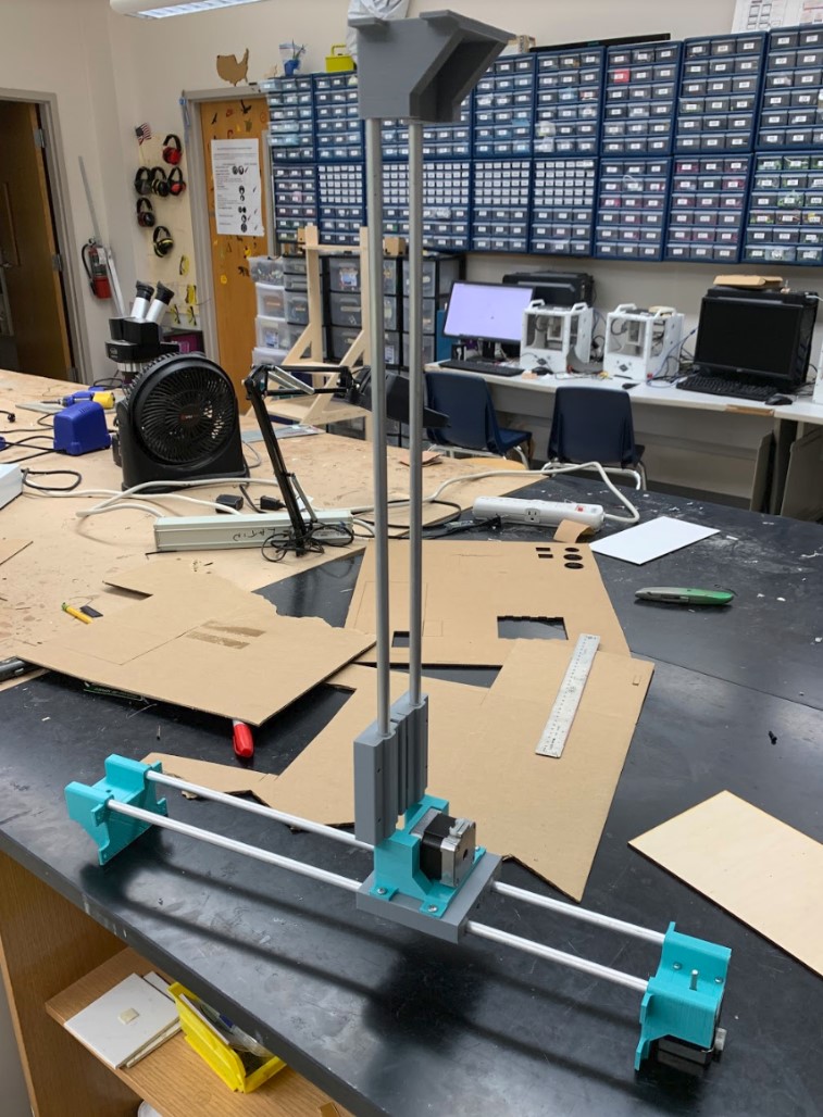
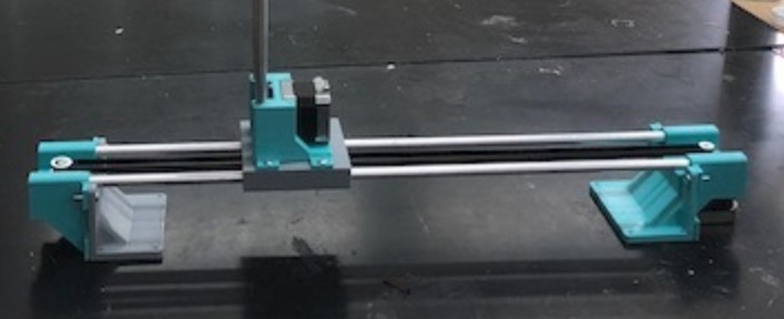
So, I knew that my real focal point for this week should be the two axes. I made a loose 3D model for the sake of comprehension just to get a feel for what the layout would look like first.
This wasn’t at all to scale, but it gave me a good idea of what I was going for. The next day, I started trying to find the motors and rodas that we would use around the lab. I ended up finding two identical two phase stepper motors, specifically model 17HS4401.
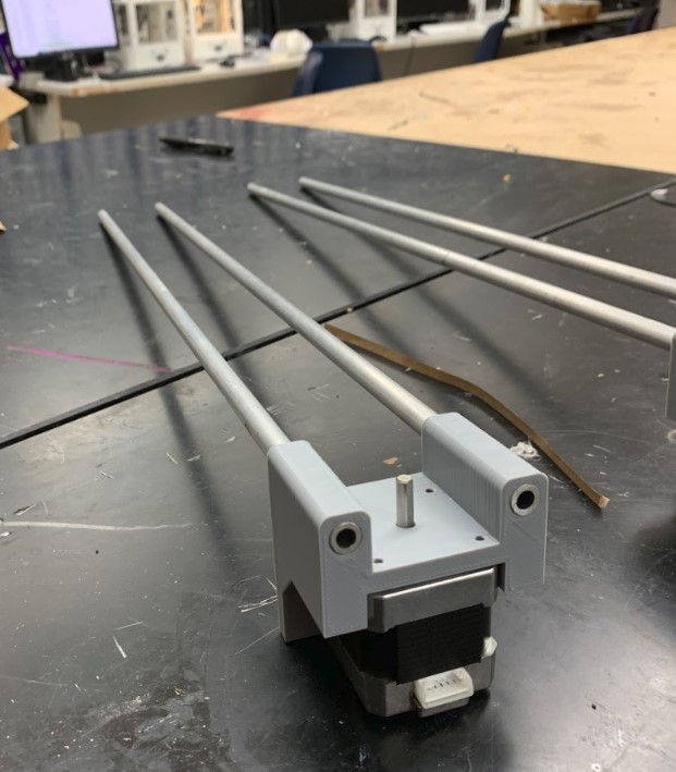
I had these, next I just needed some sort of metal dowels to act as the guidelines of the gantry. I eventually found four aluminum dowels, each sized at 3/8th inches and 24 inches long. Once I had these basic materials, I got work on a 3D printed part to hold it all together.
3D Design
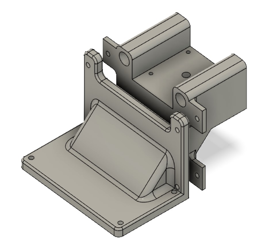
I got some calipers out and began taking down measurements of the parts, and eventually I had this made up.
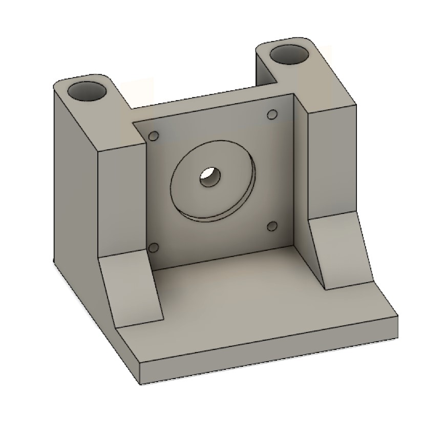
It was designed to hold the motor in place while also providing secure channels for the dowels to fit into.
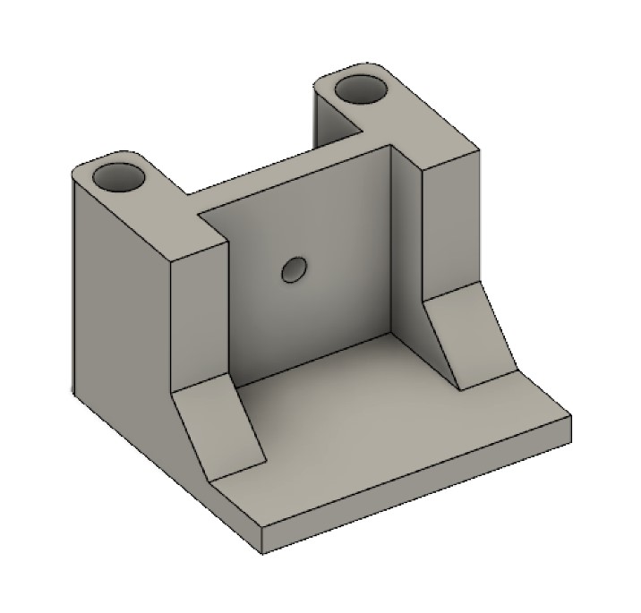
I still needed something else though. Because I was planning to use belts to pull the gantry up and down along the axis, that meant I would need some sort of idler at the opposite end of the dowels to turn the belt around. For this, I used the same design I just made previously but with a few changes to hold an idler in place of the motor.
Great, now I just had to print out the parts. I printed them out of grey PLA at 40% infill, and in a couple of hours they were ready to try out.
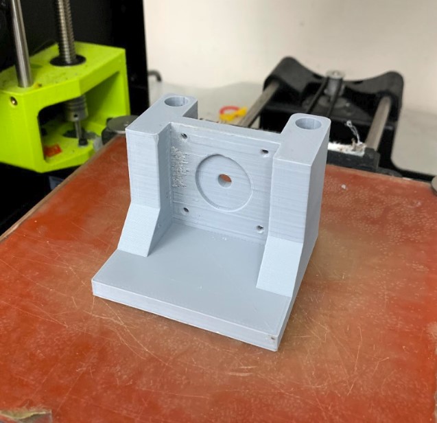
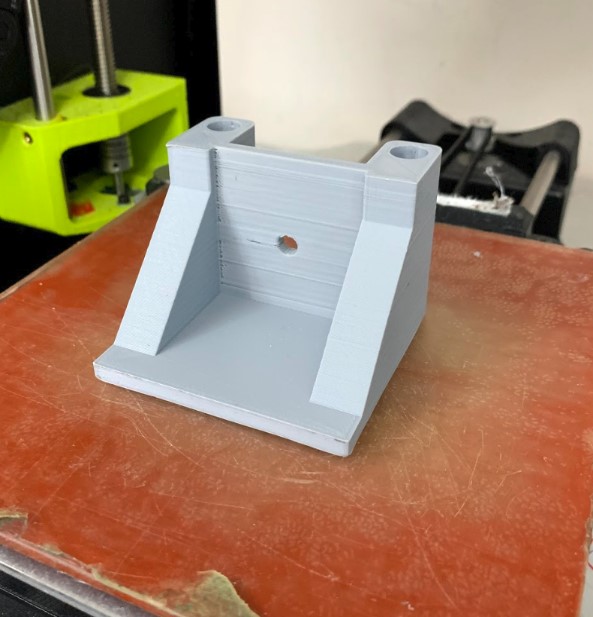
Thankfully the rods fit in very nicely, there was no wiggle room at all and they certainly were not going to come out easily.
So now I just had to make some sort of carriage that would hold onto the second axis. I got that made up pretty quickly in fusion by using the same hole placement of the dowels from the previous model as a reference.
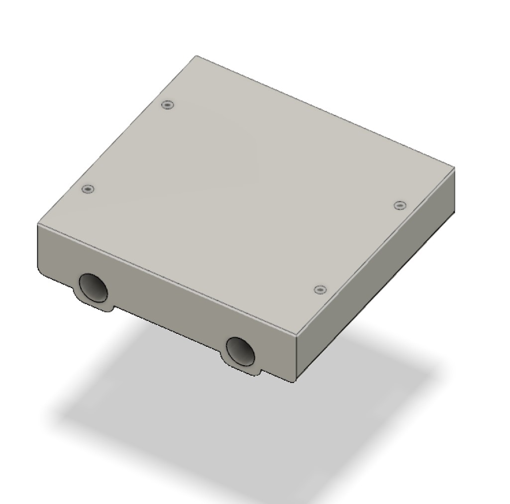
I added in four screw holes on the top to let me attach the second axis’ piece, then I started designing the piece for the second axis too.
I started with the first piece I made and I placed it over top of the carriage to see how it would all line up.
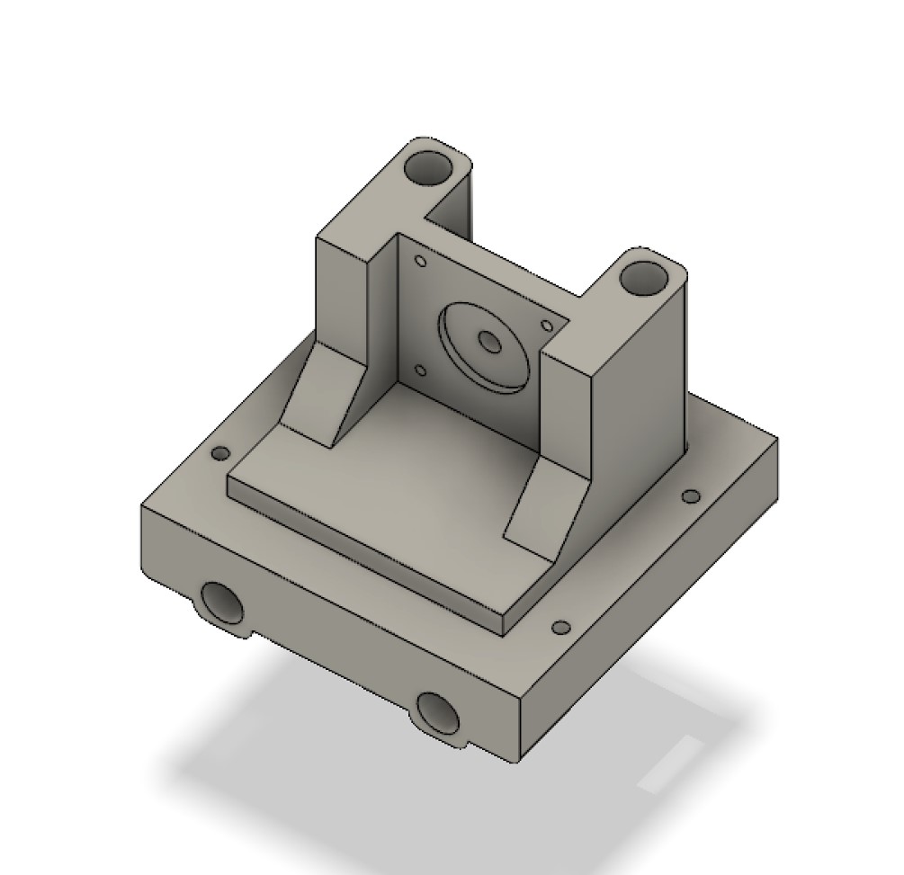
Then I added four extrusions to secure the piece to the base.
Now I could finally print out these two parts and start to see how the second axis would come together. I forgot to grab a picture of it at the time, but these new pieces worked together very well.
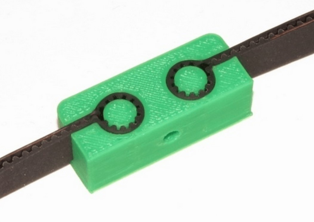
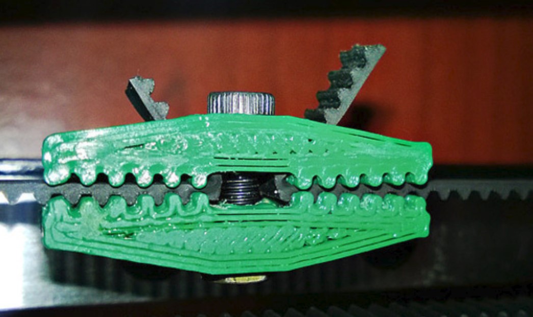
It was around this time that the belts and gears came in, and getting these in made me realize a flaw with my carriage design. I had no way of actually attaching the belts to the carriage without just glueing them on, and that obviously wasn’t going to work. I started looking at the printers in our lab and some other machines online for ideas of how to do this well, and there were two designs that seemed to be the most common.
Either the belt was being looped back into itself to hold itself in place, or the printed plastic around the belts also had teeth on it that held the belts in place through compression.
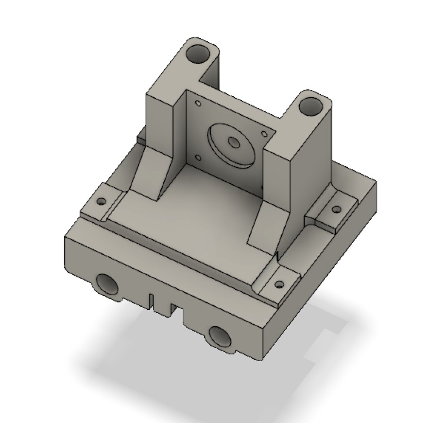
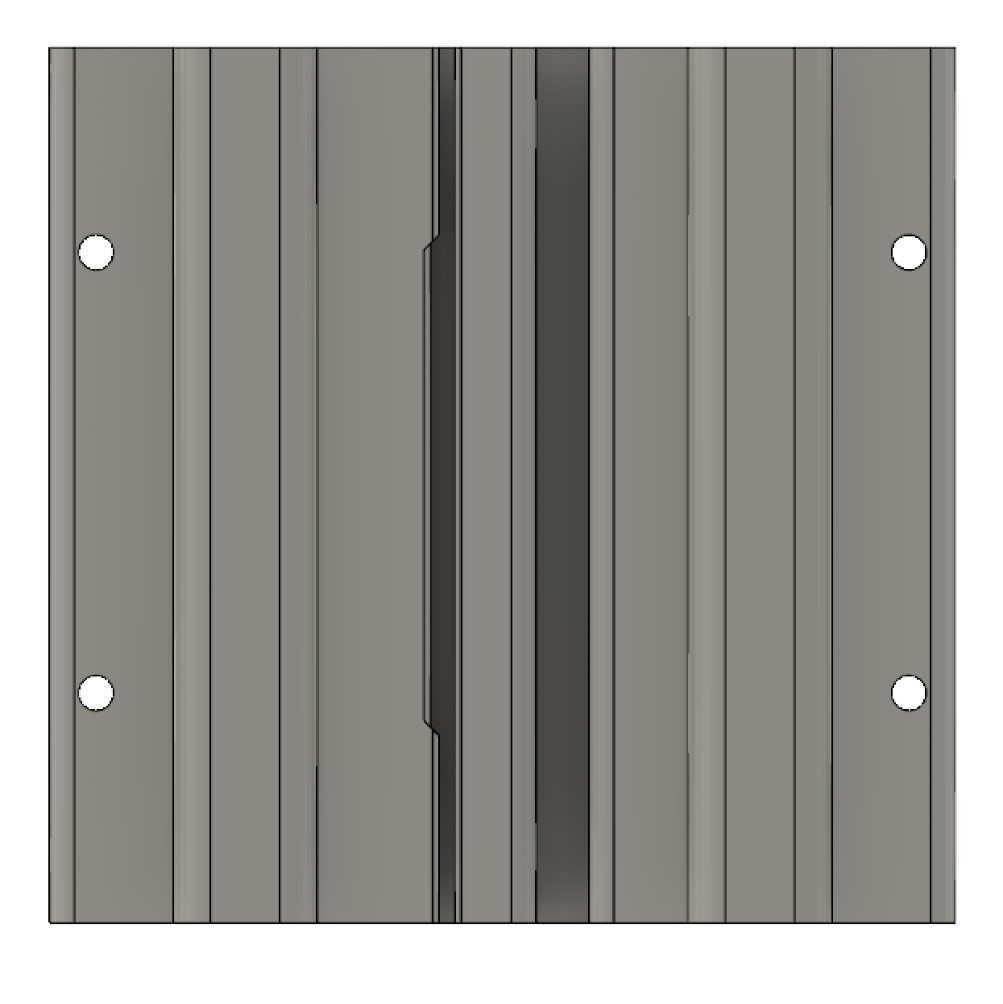
I ended up using something a bit easier for me to come up with and design, but it has ended up working just as well. Rather than using the same piece of the belt on itself and trying to find the correct sizings for the loop and everything, I just made a slight opening for a second, entirely separate piece of the belt that cut off and placed in nxt to the two ends of the first belt. This way, the belt was securely held in place, and I could reliably print it all as one part.
So I printed out this new carriage and once it was finished up, I realized that I was gonna end up needing some way of securing the base of the machine down to the base of whatever box we were going to use. Rather than going in and designing a whole new part, I just printed out more of the ones I made previously with the screw holes on the side and figured I would just come up with some way to work with those later.
So at this point I designed another piece that would fit onto the base and allow it to easily be screwed down.
These pieces printed well, so I got them attached right away.
Here are all of my files from this week.