12. Output devices
This week, our individual assignment was to add an output device to a microcontroller board and program it to do something. I wanted to jump into something called “charlieplexing” which I’d never used before. Our group assignment was to measure the power consumption of an output device.
Group Assignment
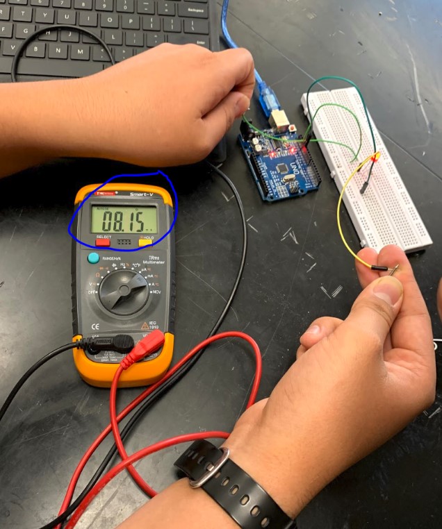
Our group assignment was to measure the power consumption of an output device. To do this, we used a multimeter with an arduino and an LED to see how much power in milliamps the LED pulled. We hooked up the arduino to just turn on the LED, then we measured the LED with the multimeter and found that it was taking 8.15 mA to power.
Individual Assignment
For my individual assignment this week, I wanted to do something with charlieplexing. I had heard the name of it before and I had seen a charlieplexed array of LEDs turn on, but I never actually understood it all until this. The first thing I did to start learning was just googling simple examples of charlieplexing, and there were actually quite a few good explanations of it around the web. I’ve linked below all of the different resources I used.
Charlieplexing explained like I’m five
I also looked at the site of Elia De Tomasi.
I read all about what Tri-State Logic is in microcontrollers, and how it can let you set a pin to an Input, an Output, or just Off. One of the images I kept on seeing through a lot of these resources was this one below, which shows the most basic way to charlieplex a set of six LEDs with three pins.
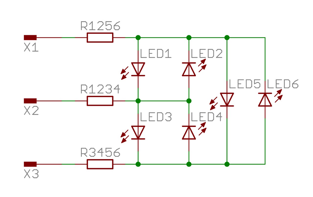
In the image above, any of the three pins can be set to INPUT, OUTPUT, or just simply off, to individually address each of the six light emitting diodes. I wanted to see this in person, so I got out an arduino and a breadboard and wired up a quick example with six big red gumdrop LEDs.
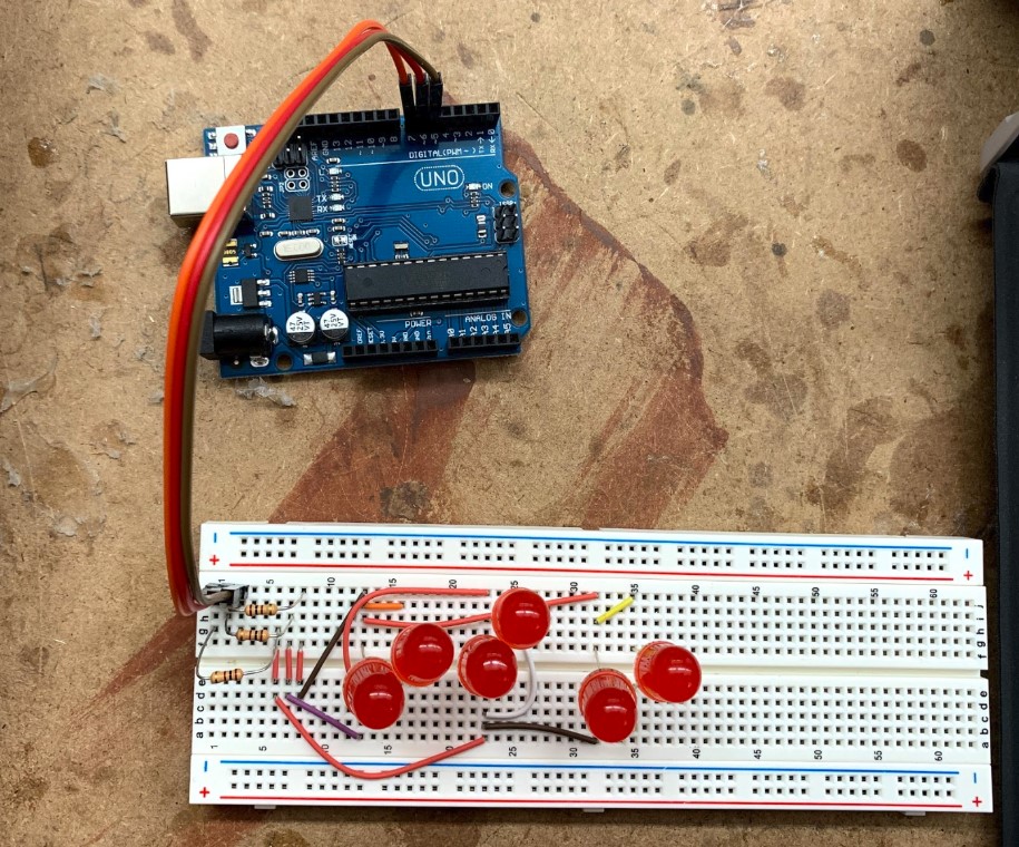
Breadboarding
For the code, I looked around the different sites and eventually used the script from the “arduino and charlieplexing” as well as the “Charlieplexing with Arduino” resources to light up all of the LEDs. I think my issue was that the breadboard had some shoddy connections and that the wiring didnt translate very well over to the breadboard layout in the first place. All I could ever get to turn on was four of the LEDs, the other two never got power, and I think this is because the basic charlieplexing layout also relies on electricity taking the path of least resistance, which was not set up correctly here.
Eagle
I decided to try a more efficient means of making this small example work, so I made a tiny board design for it rather than trying to use a breadboard. First, I made a schematic to match the proper layout.
Then I routed it all in the board designer, sent it over to bantam, and got it cut on our milling machine.
Then I soldered on all of the components and connected it to the arduino.
Finally, I plugged the arduino into power, and it worked!
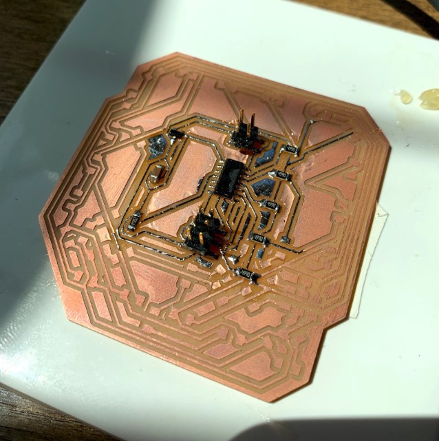
Main Board
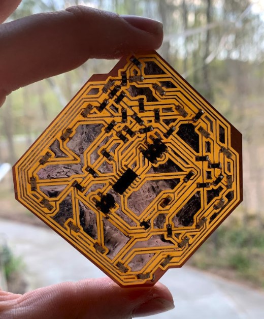
Now I wanted to move on to my main challenge this week, full scale charlieplexing based off of one of the example boards that Neil has up on the lecture notes this week.
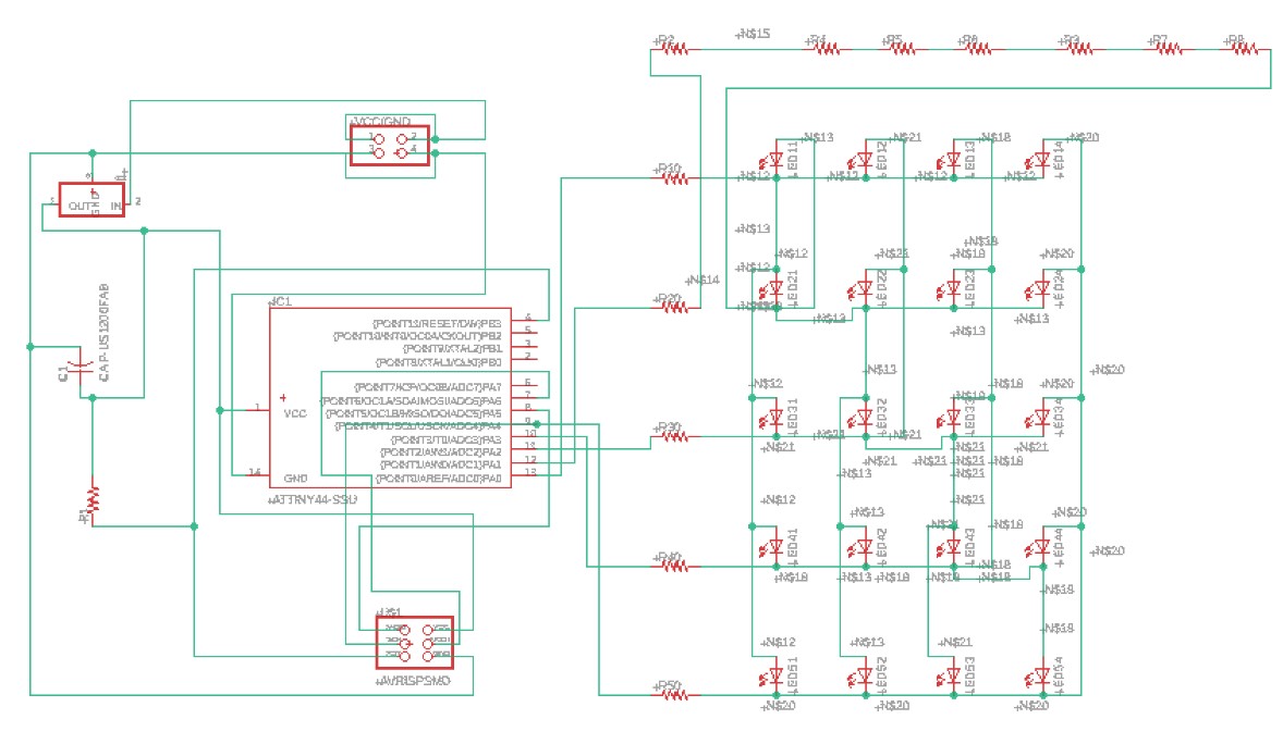
I knew I had to change the board up somehow, so I only used 18 jumper resistors rather than the twenty that neil had on his example, and I completely changed up the layout of the LEDs to make a ring rather than an array. My idea was that since the example code that niel provided turned on the LEDs in a certain order, I could make a ring with the LEDs placed in that same order and have a spinning ring of LED lights when I ran the code. I started by looking at the example layout he provided for my schematic connections.
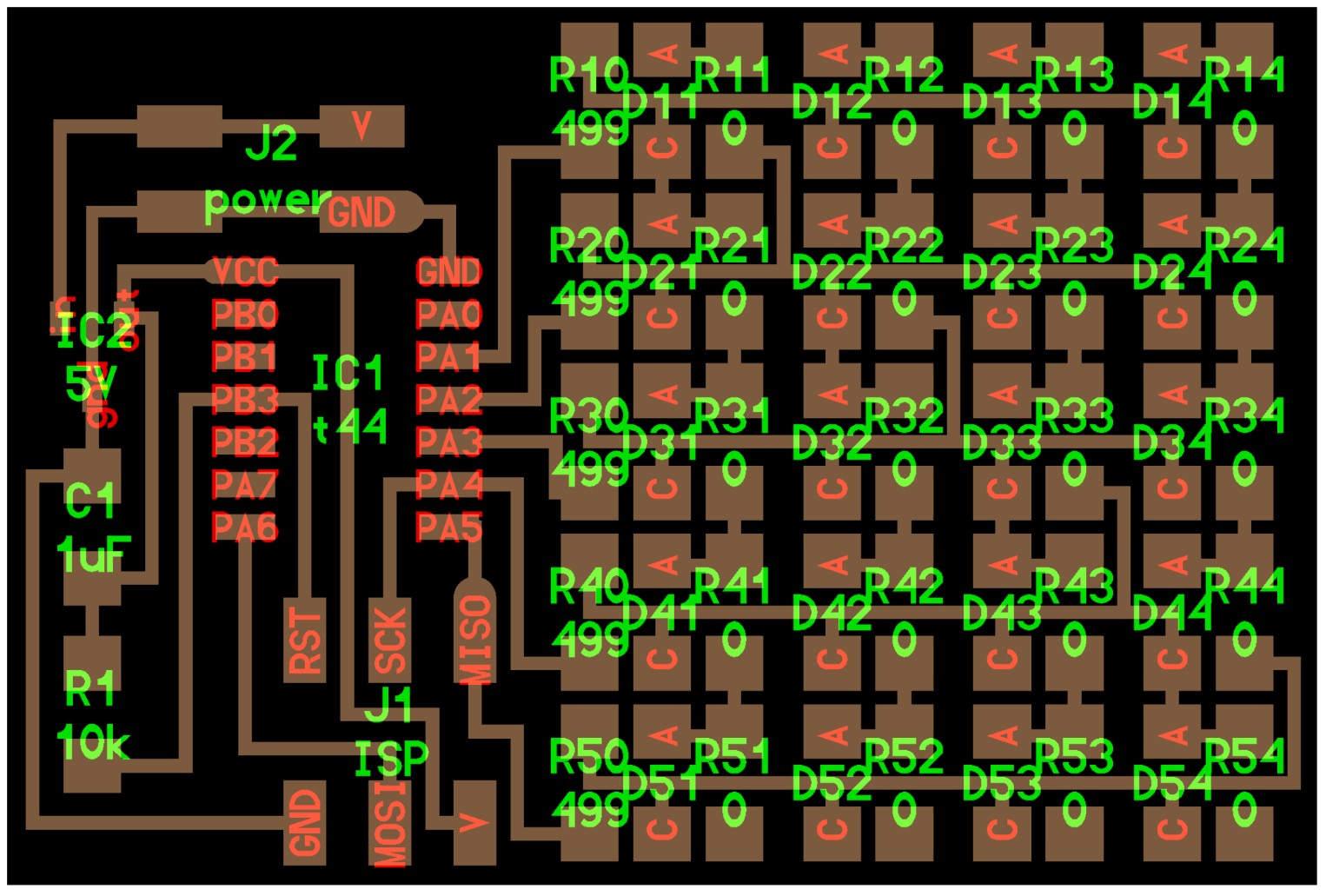
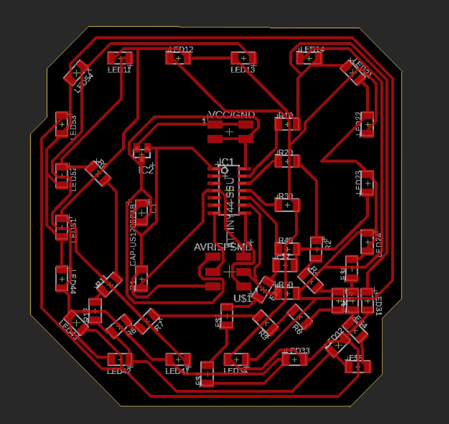
Then I got it pulled up in the board editor and spent a very long time trying to get the pieces laid out in a way that the autorouter could work with. I tried a bunch of different setups, then finally I ended up with this.
Milling
I got it pulled up in bantam tools afterwords, then I configured all of my settings. I set it to use a 1/64th inch bit on a 1.82 mm thick piece of single sided PCB stock.
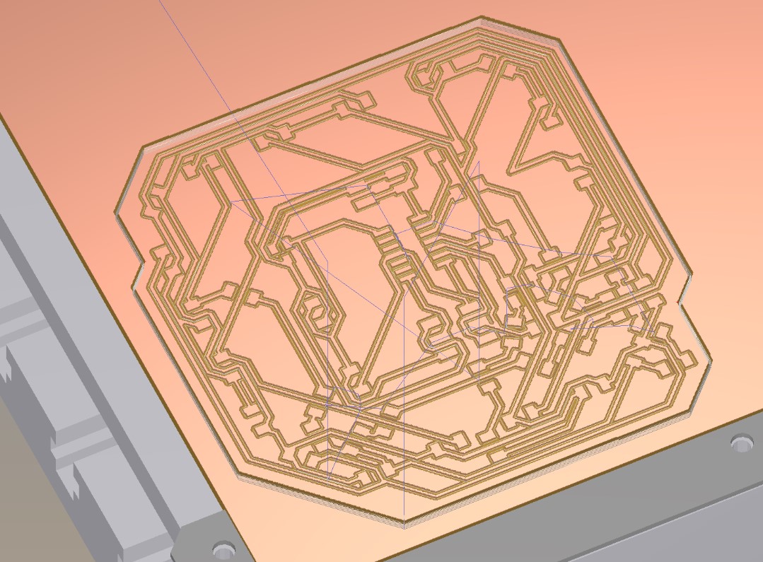
Then I homed all of the axes, got the material put down, and started the cut.
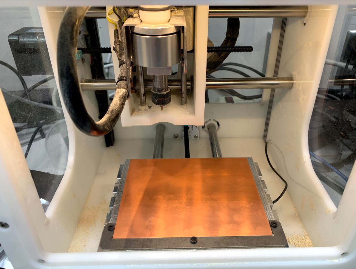


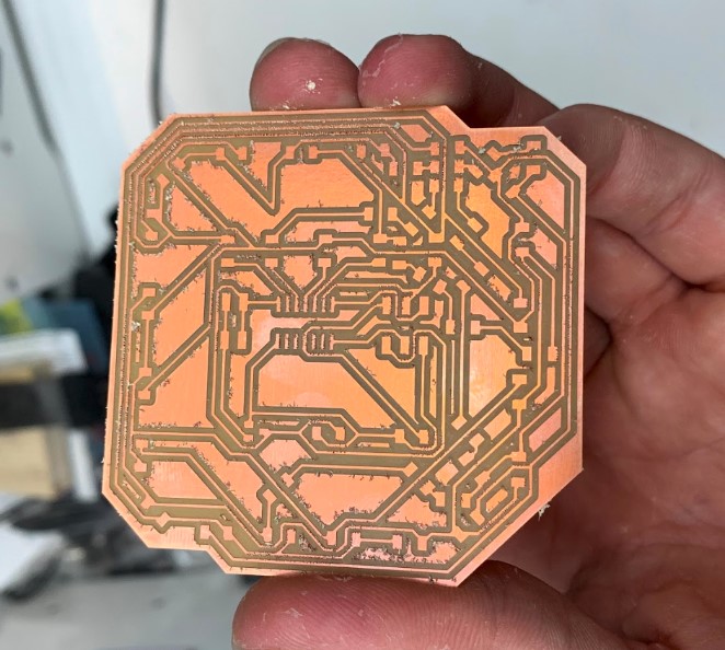
The cut went well. Once it finished up I got it pulled off of the cutting bed and observed my board.
Soldering
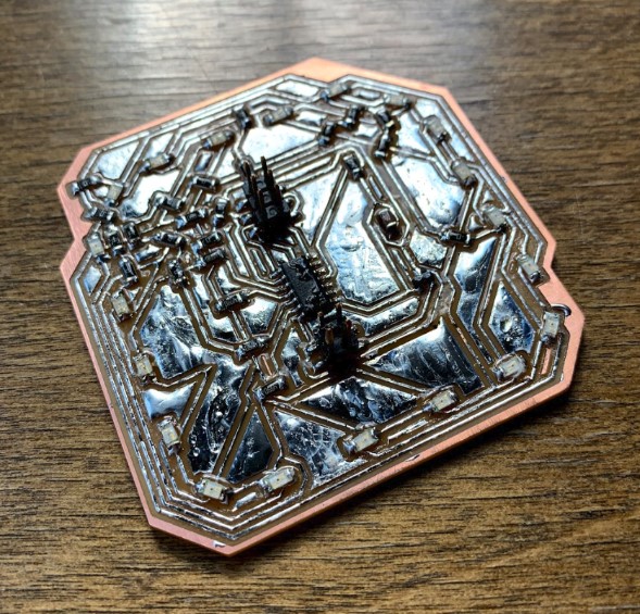
I got most of the burs taken off from the edges, then I set up my board on the tile at home to start soldering. As you can probably imagine, I had quite a few components to work with for this board.
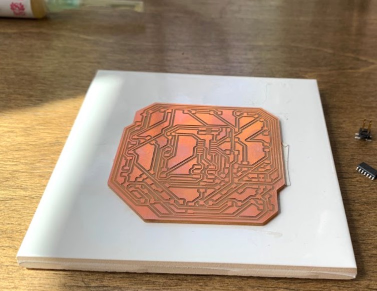
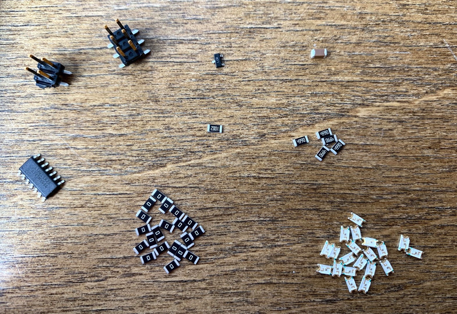
Here are some photos I took throughout my work.
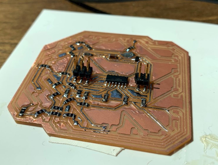
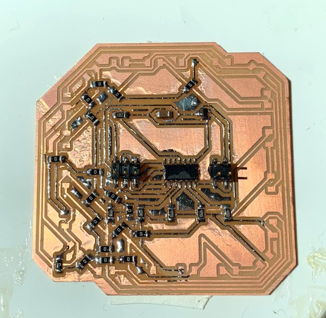
Here is my finished board after about an hour of soldering.
Programming
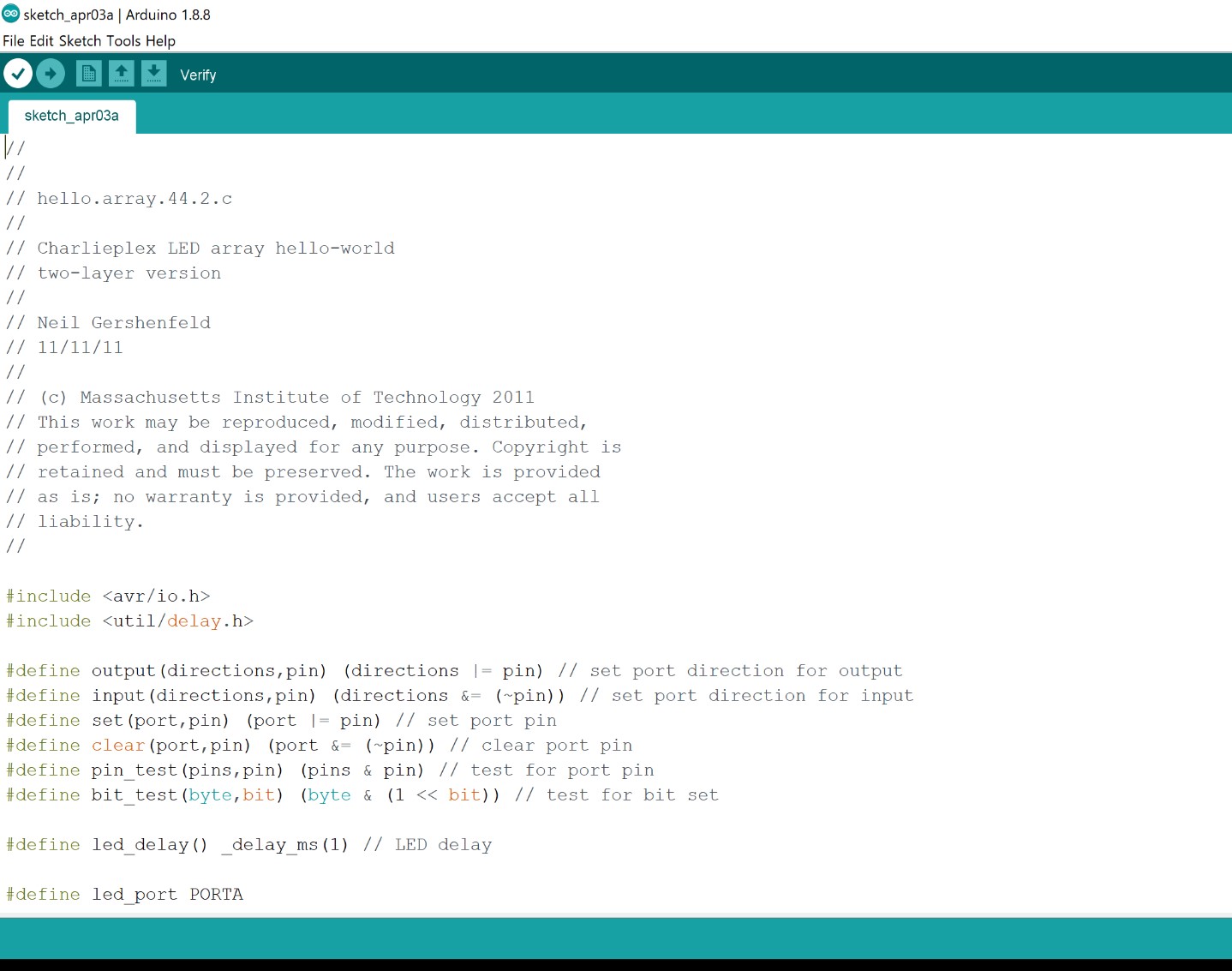
The next step was to program the board. Once again I got the C code off of Neil’s notes and put that over into arduino.
I hooked up my programmer again and gave power and ground to the board with a couple of jumper wires.
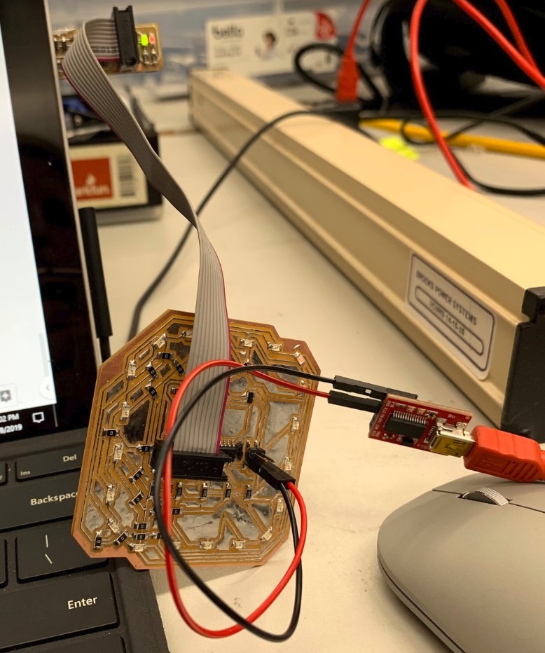
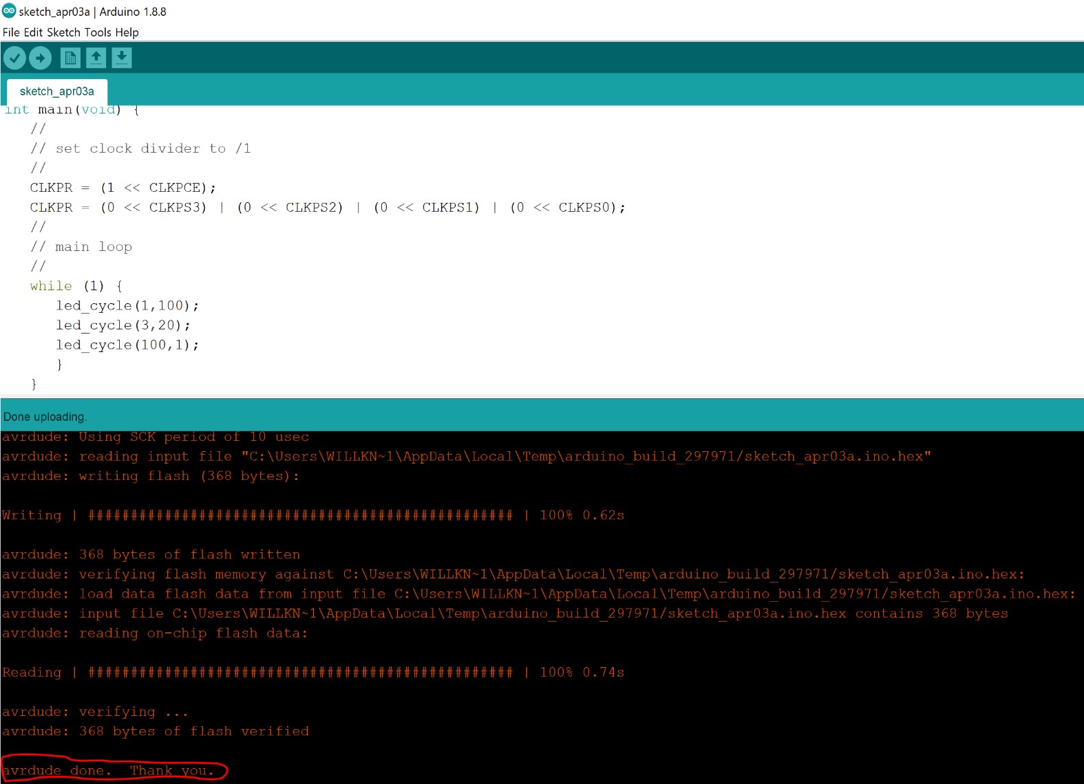
Then I uploaded the code to the board using my USBtinyISP.
The board works for the most part. Overall, it has the desired effect of a glowing ring of spinning LEDs, which I was really excited about. However, about five or six of the LEDs aren’t turning on in the desired order, and two of them just dont turn on. It still looks like a really cool spinning ring, but when you get down to it, there’s ~8 LEDs that don’t function as intended.
The Issue
I do know now what my issue is, and it all comes down to the three main things that I have found to be necessary for charlieplexing. The first of these is that you have to use Tri-State logic, It just doesn’t work out otherwise. The second is the fact that these LED lights are diodes, (it’s in the name, Light Emitting Diode), which means they only let current pass through in one direction, and they stop the flow of current in the opposite direction. The third, and in retrospect the most obvious, of these things is how electric current will always follow through the path of least resistance.
In a properly wired charlieplexing board, there may be four or five different paths that current could flow through when you turn on two of the pins to light up a single LED. However, those other paths will never be taken because to get from one pin to the other, the current wants to pass through the least number of LED lights possible. The correct path, and the one that will always be taken, should only have one LED between the OUTPUT and the INPUT pins. There may be other routes that connect these same pins, but these other routes will alwayse have more than one LED along the path, meaning none of them will be taken because the current wants to follow the path of least resistance, the path with only one LED.
That’s what I did wrong with my board. I didn’t set up the LEDs so that the path of least resistance would always be followed as expected, and that led to the erratic behavior that you will see in the video below.
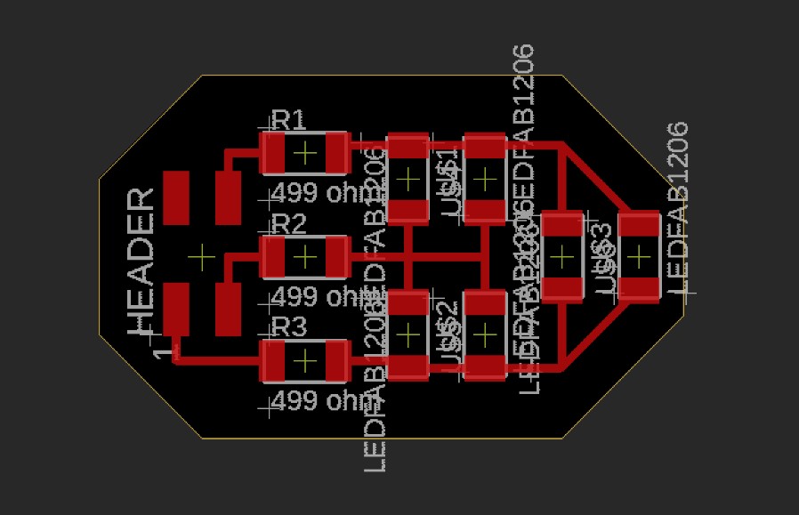
Extra practice
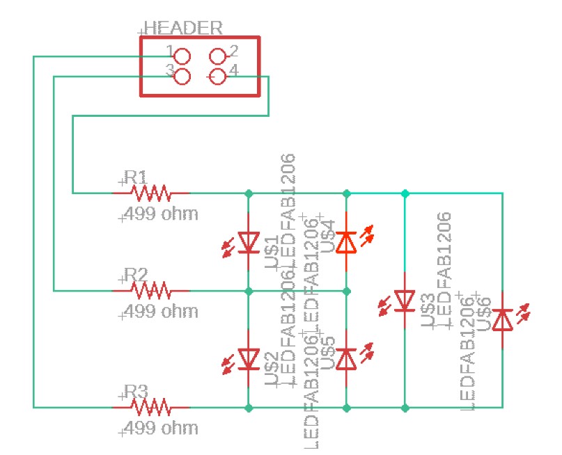
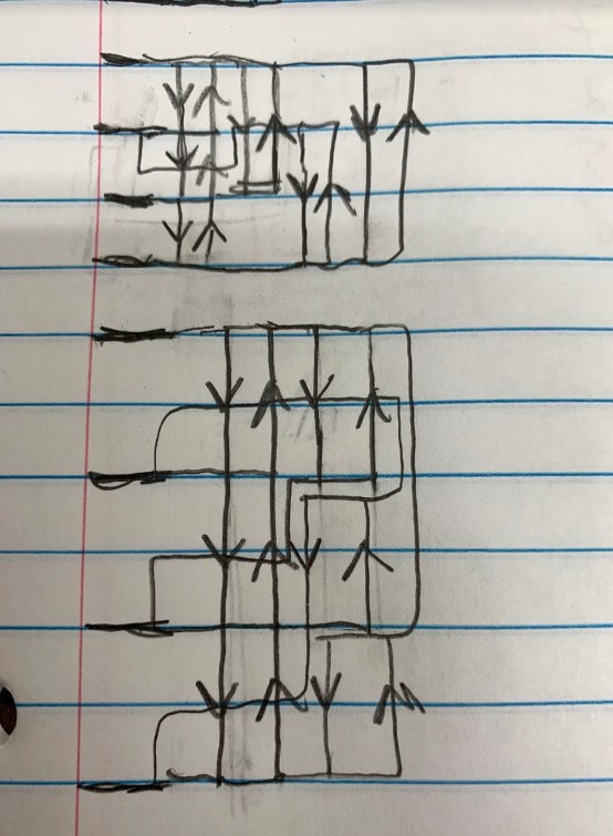
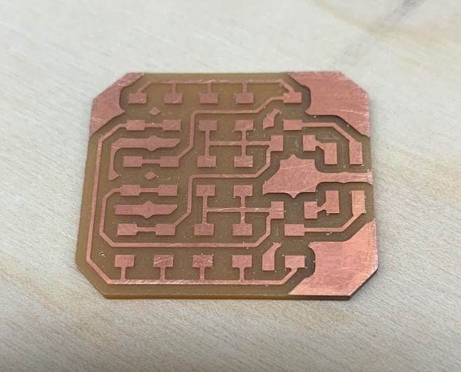
I still wanted to make my own properly working charlieplexed board, so I decided to make one that uses four pins for a resulting twelve possible LED lights. Rather than trying to do it with an Attiny44 like I did with the ring, I just chose to use a four pin header and an arduino. I spent a while trying to draw out what it would look like on paper, here are some of those sketches.
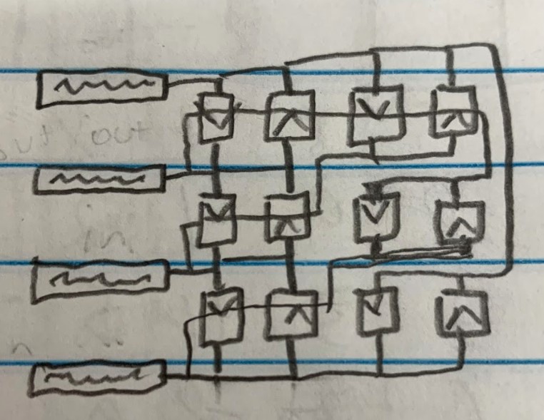
Once I felt like I had a good layout, I made a quick schematic of it.
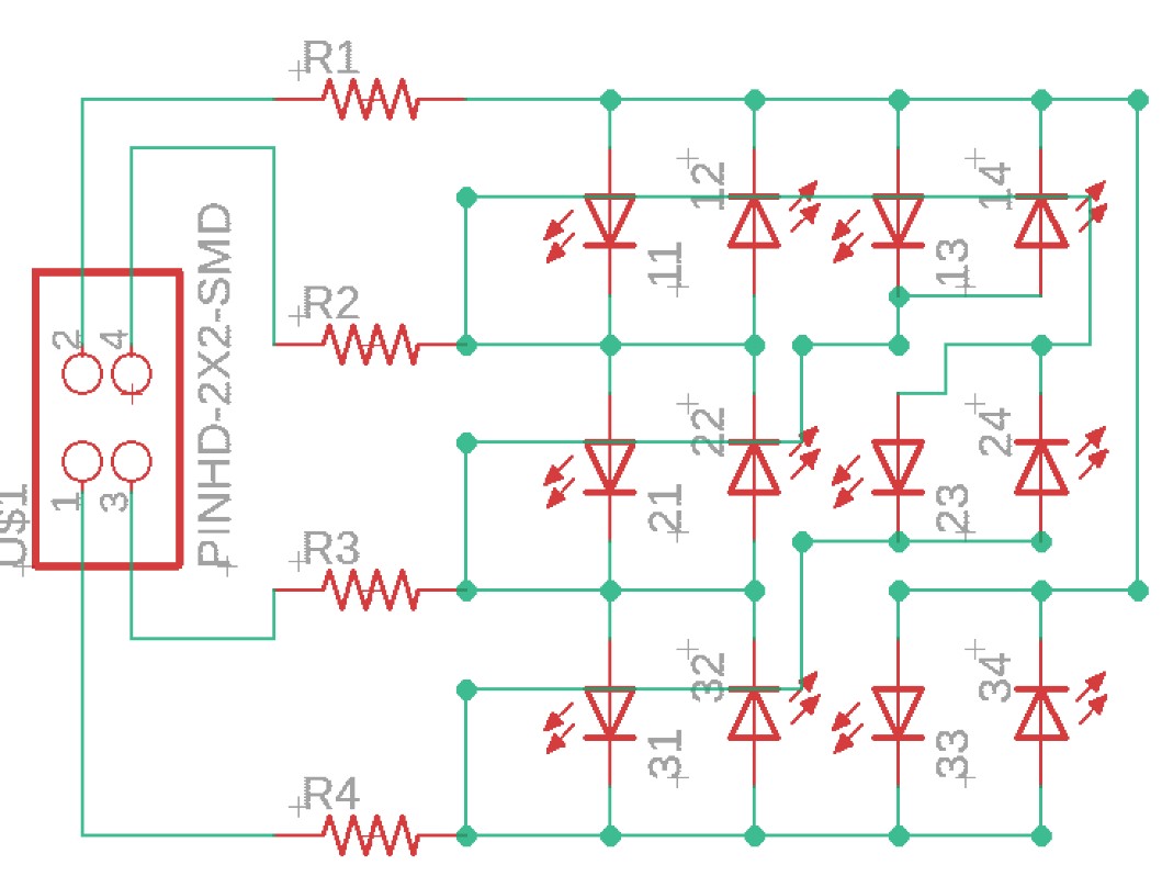
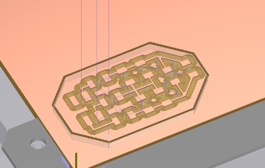
Then I took that over to the board layout and routed all of my traces.
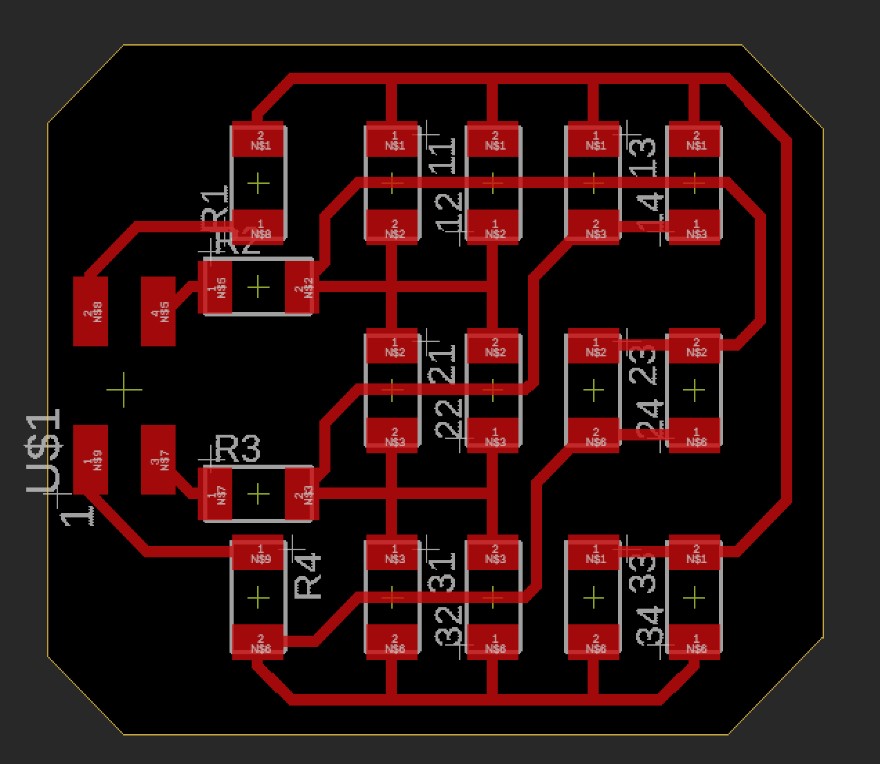
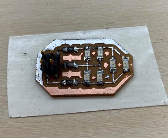
Once I had the board file made, I sent that over to the bantam tools software and got my board cut out on the milling machine. The cut was pretty easy at this point with all the practice I’ve had in previous weeks, so I won’t include more pictures of that here. The board looked great, so I went ahead and got it soldered up.
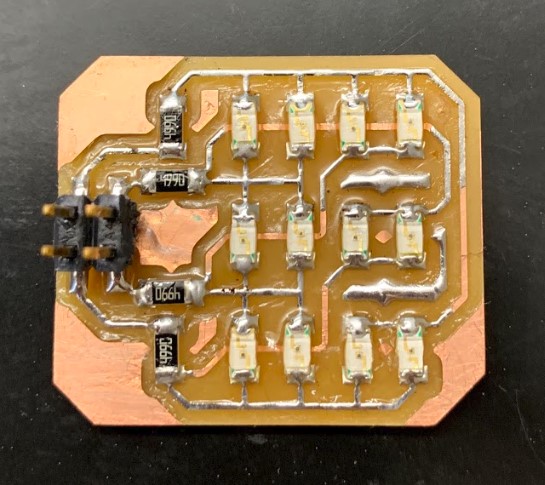
The Code
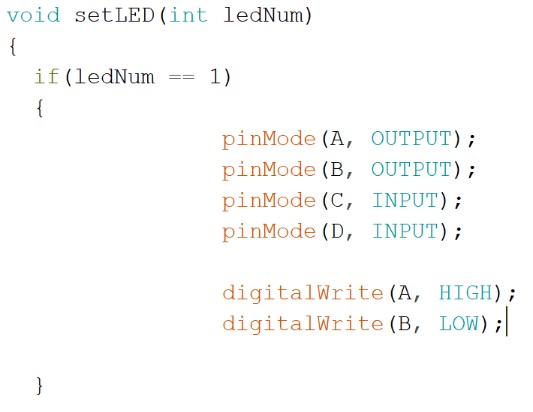
I ended up modifying the code from my smaller example with only six LEDs to work with four inputs, and therefore a resulting twelve LEDs. It wasn’t too hard to do, especially since I had most of it already down for me.
I started by adding two new integers into the code. The first one was just “D” and it corresponded to the correct pin that I would be outputting from, which was pin 2. The second one was an integer I added due to what I learned from the inputs week. I called it “T” for Time, and later on in my code when I would sequence the LEDs with specific timing in milliseconds between them, I would just put down “T” and then change this one variable up top rather than having to go in to individually fix each of the timings. The last thing I added was in the setup code, and it was just telling the chip to use this new integer “D” as an output.
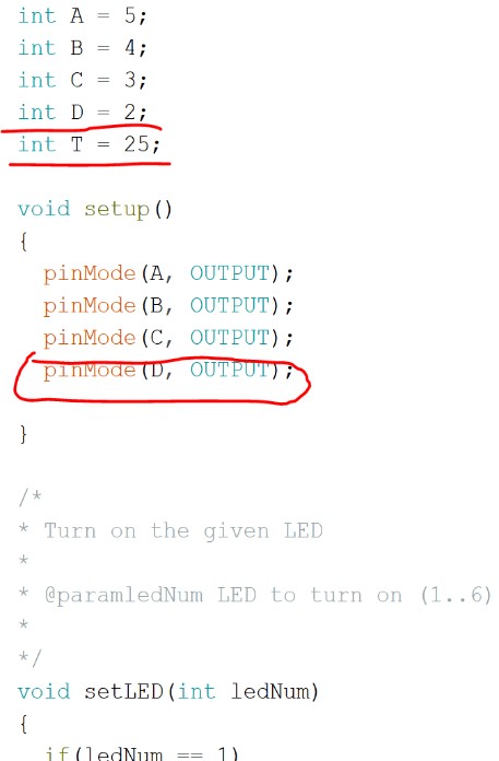
Then, I had to go in and change all of the pin initializations for each individual LED. In the example code that I used before, to set a pin as the output pin you would make it output high, then to set the input put you would just set it as input, and to turn off any unwanted pins you would set them to output low. I figured I would follow the same logic for mine since it really wasn’t much of a difference. Below you can see the code I used.
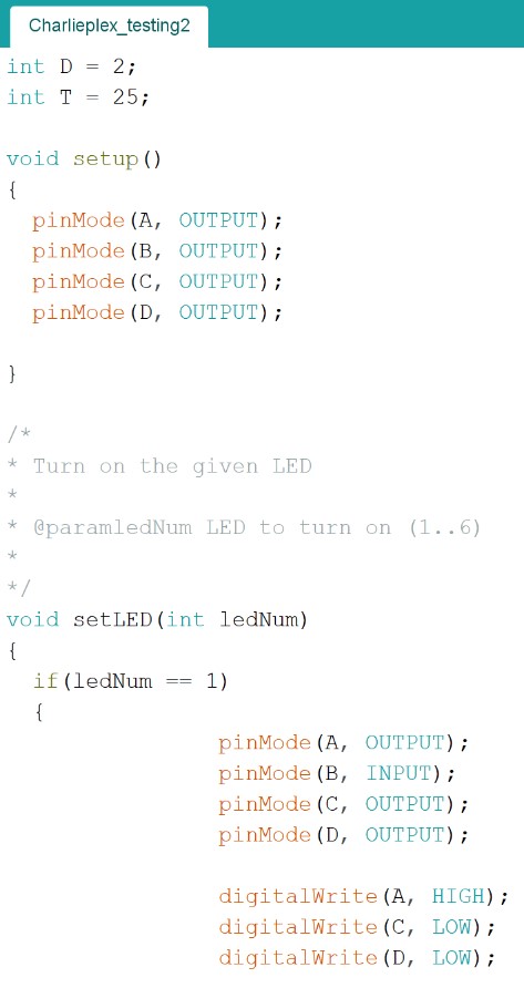
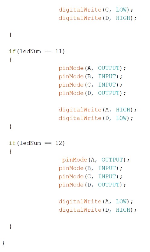
I did the same thing for the other 11 LEDs, setting the correct pins as inputs and outputs, high and low, depending on what was needed for that specific LED. Once I had it all changed, I went down to the main loop and set it to just turn on the first LED so I could be sure things looked correct.
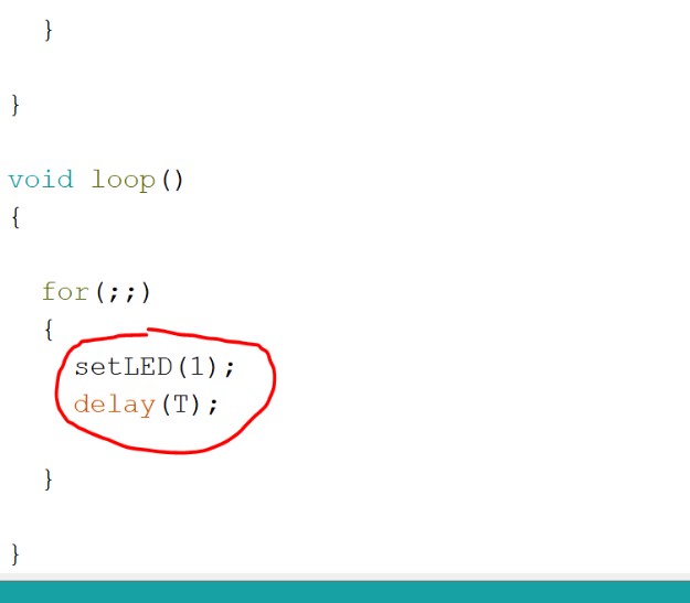
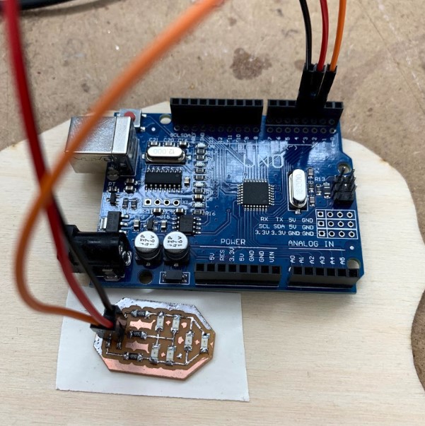
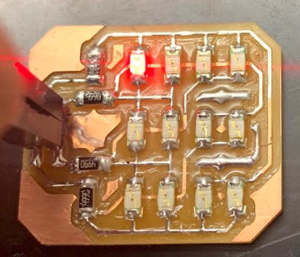
My code uploaded just fine, (no surprise there since it was an arduino), but it wasn’t acting as expected. Rather than turning on the first LED up in the top left, two seemingly random ones were turning on.
I spent a while trying to figure out what was going on, and eventually I realized something odd. The two LEDs that were turning on were the ones that followed a path to the two pins set to output low. This was odd, because those pins were supposed to be set to off. Then I realized that the one set to input was the one that was off. It was kinda a shot in the dark, but I went and tried setting the pin that I wanted to be an input as an output low, then I set the two pins that were supposed to be off as inputs. I uploaded it and watched as somehow, it worked.
I didn’t quite know why it was working, but I went with it. I changed all of the other LED configurations to resemble this backwards way of turning on the LEDs, then I set the LEDs to run one after the other in order from 1 to 12.
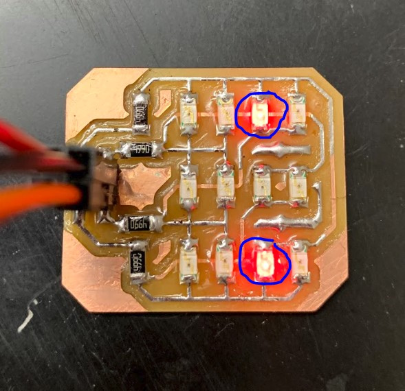
Charlieplexing Effects
So, its working!. I felt like going on and doing some other cool effects with it, so I’ll include videos of that below.
After some more work with the board, I realized that by setting the timing between LED blinks to just one millisecond, I could make it look like they were all on at once because my eyes aren’t fast enough to see the blink.
This was really fun to do. I enjoyed getting to see my creation work in so many different ways, even if I didn’t quite get how, and all of this practice with charlieplexing will hopefully help me with my final project.
Here are all of my files from this week.