3. Computer Aided design
This week, our assignment was to create a 2D/3D model of a possible final project using a CAD software.
CorelDRAW
I began this third week by creating a sketch of a possible final project on a 2D CAD software called CorelDRAW. I already had Corel on my computer for use in some of my other design based classes at school, so there was no need to download any new software.
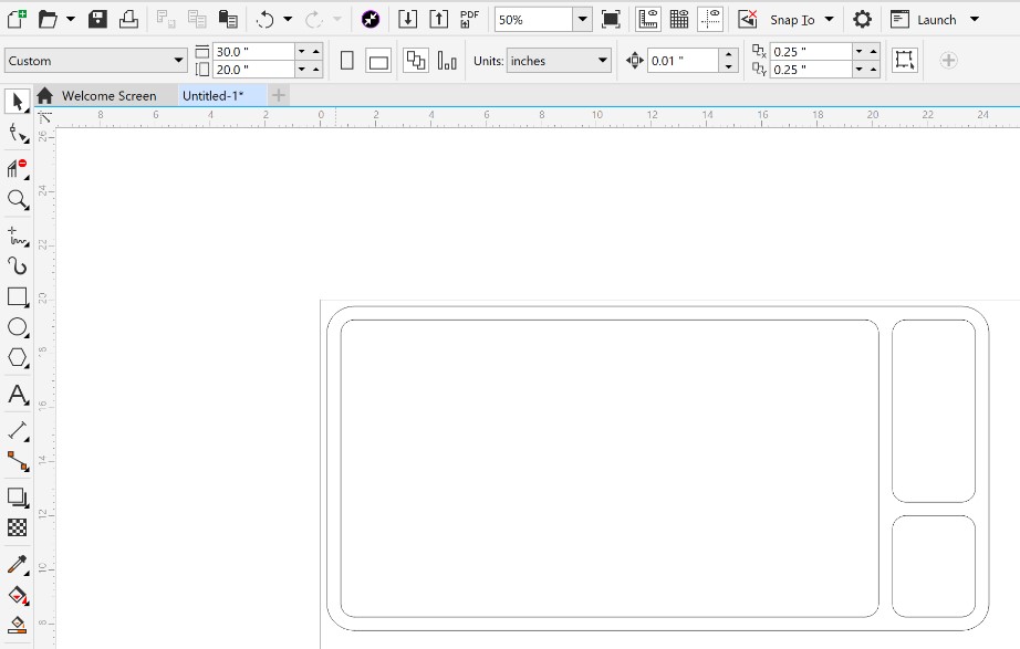
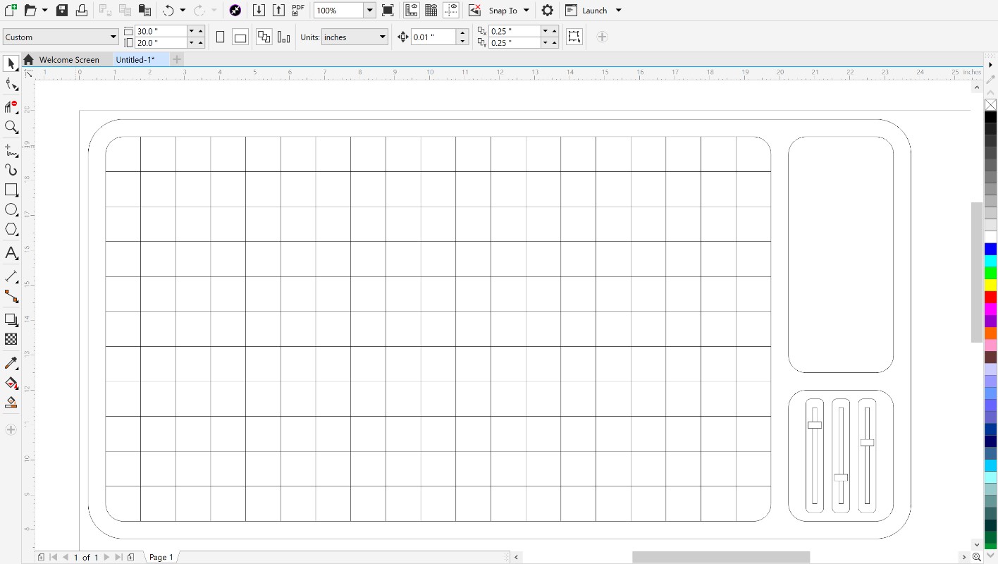
The first thing I did in Corel was just getting a basic outline of my idea. I worked on rounding out the edges and sizing everything to fit nicely together, and ended up with this.
Allot of the designs I make in Corel are only possible because of a very helpful feature called “Virtual Segment Delete”. It makes it possible to only cut away individual parts of a sketch object you made based on how the vectors of that object intersect with others. Here’s an example:
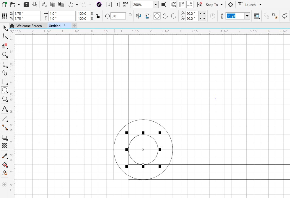
In this image, I have all of the shapes that will make up the final corners layed out over each other. As you can see, there’s lines all over and it’s kind of tough to imagine a smooth corner coming out of this jumble, but with the Virtual Segment Delete tool it’s actually not hard at all.
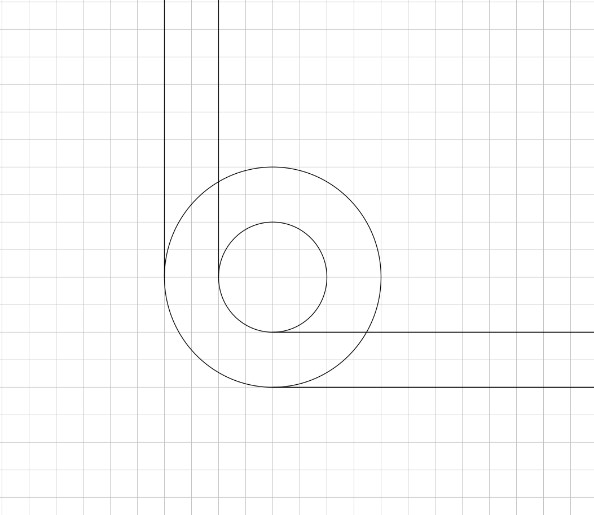
Here’s what it looks like mid-process. You can see how the tool only cuts away lines up to where they intersect with others, not just every part of the original shapes.
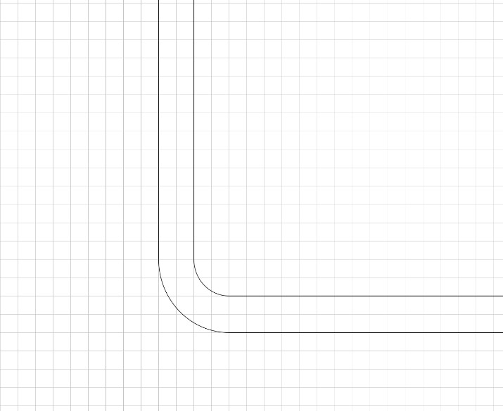
Lastly, here’s the finished curve that makes up one of the corners of my design. If you’ve been paying close attention, you might have noticed that what I’m actually doing is just laying out the bottom left corner of the circle in its necessary location and trimming away all of the excess that comes along with it.
Next, I began creating the linear potentiometers as well as the array of “Pixels” that I hope to have. I’m not sure that I’ll be able to actually include this many LED lights in my final project but the sketch below does a good job for the sake of representation.
The last thing I did with my sketch in Corel was something I’ve never really looked into before, adding color. In the past, all of my designs on Corel were just getting sent straight to our class’s laser cutter without any need of extra colors, but since this is just meant to give me an idea of what my project will look like in the end, I wanted to make it look a bit more realistic.
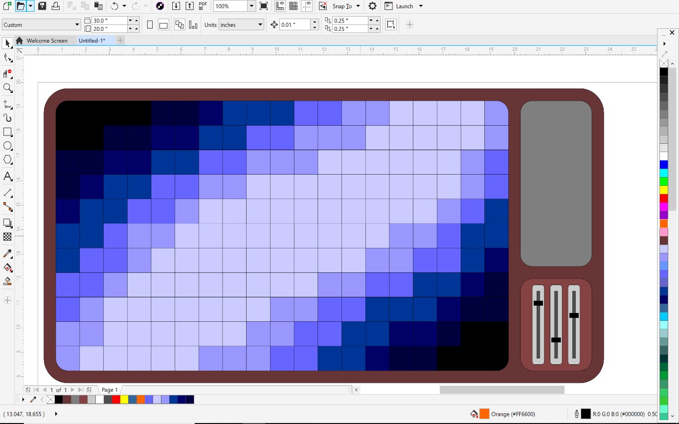
I’m really happy that I tried this. The colored design looks pretty great, and in the meantime I used a new aspect of Corel that I’ve barely even touched before. Plus, in the end, it wasn’t even that difficult to figure out.
Fusion 360
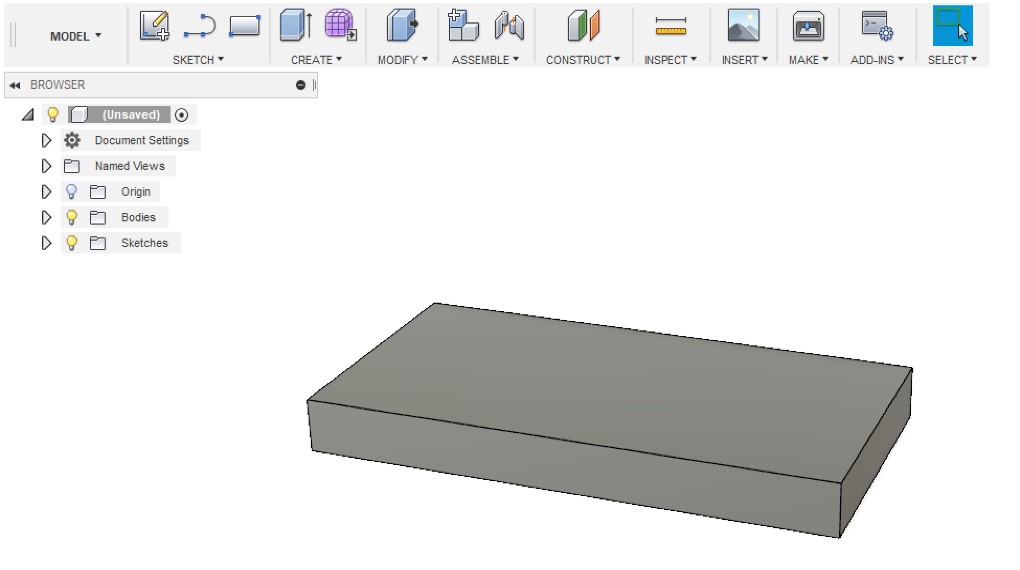
The next thing I wanted to do in terms of modeling was create a 3D model on Fusion 360. I’ve used Fusion 360 quite a bit for my engineering class to do things like create 3D printed parts, make quick examples of ideas in my head, or even just to design random objects for the fun of it. Now, I want to put my skills to the test and create a very detailed three dimensional representation. I started out simple again, just as I usually do when working in Fusion, and added on from there. The first thing I made was just the basic rectangular box outline.
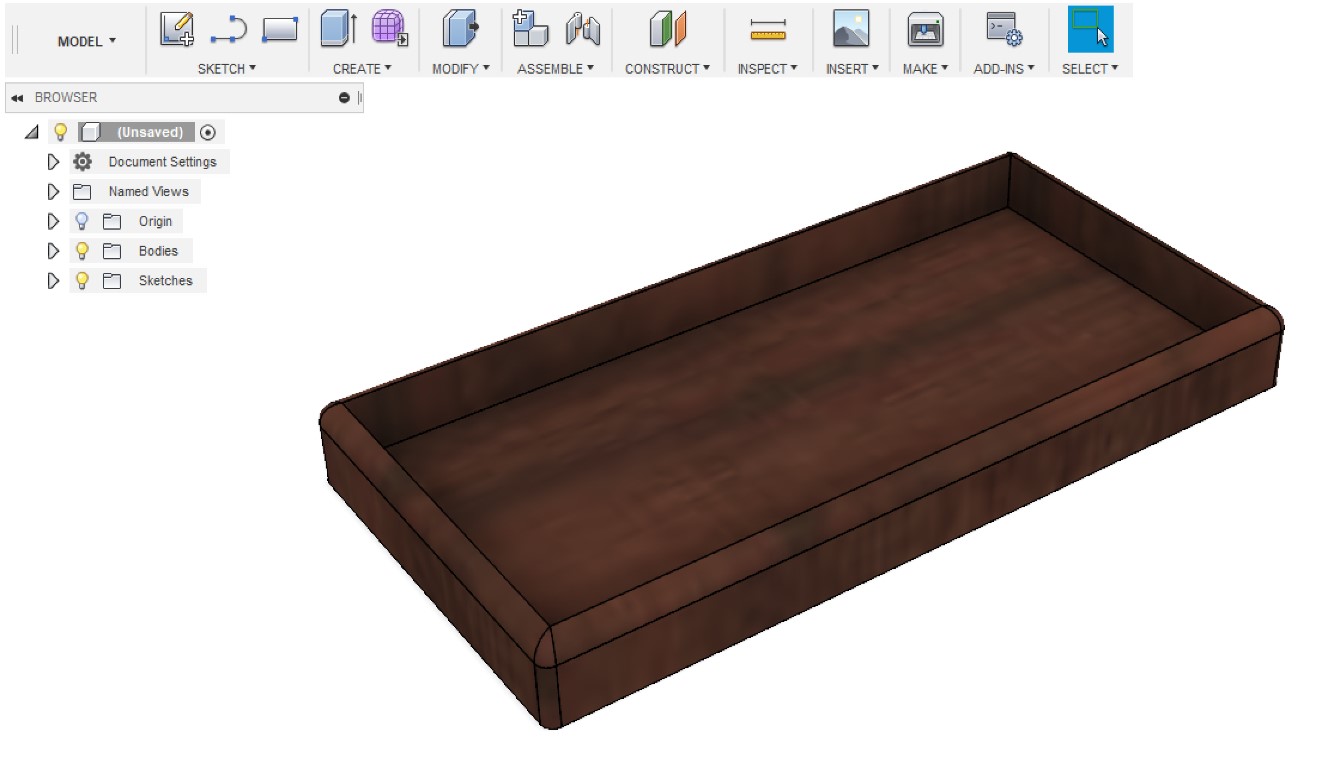
Next up, I rounded off some of the sharp edges, added a mahogany wood texture to the box, and hollowed out a space for all of the internals.
After that, I created another object that will fit into the wooden box and provide spaces for all of the individual functions of my project.
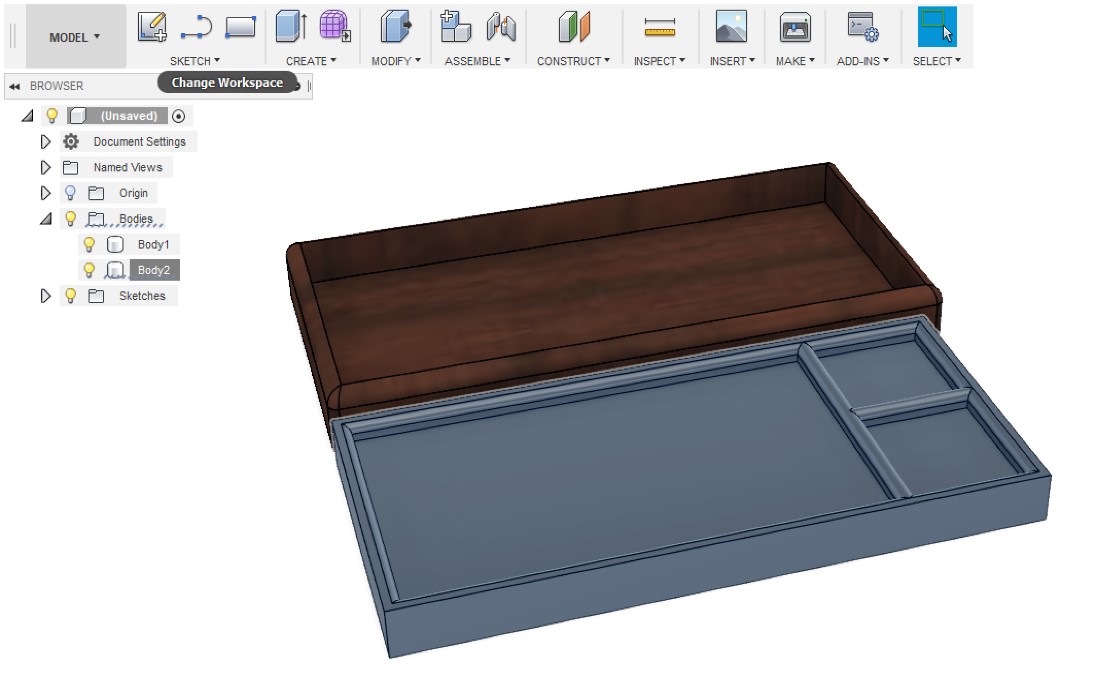
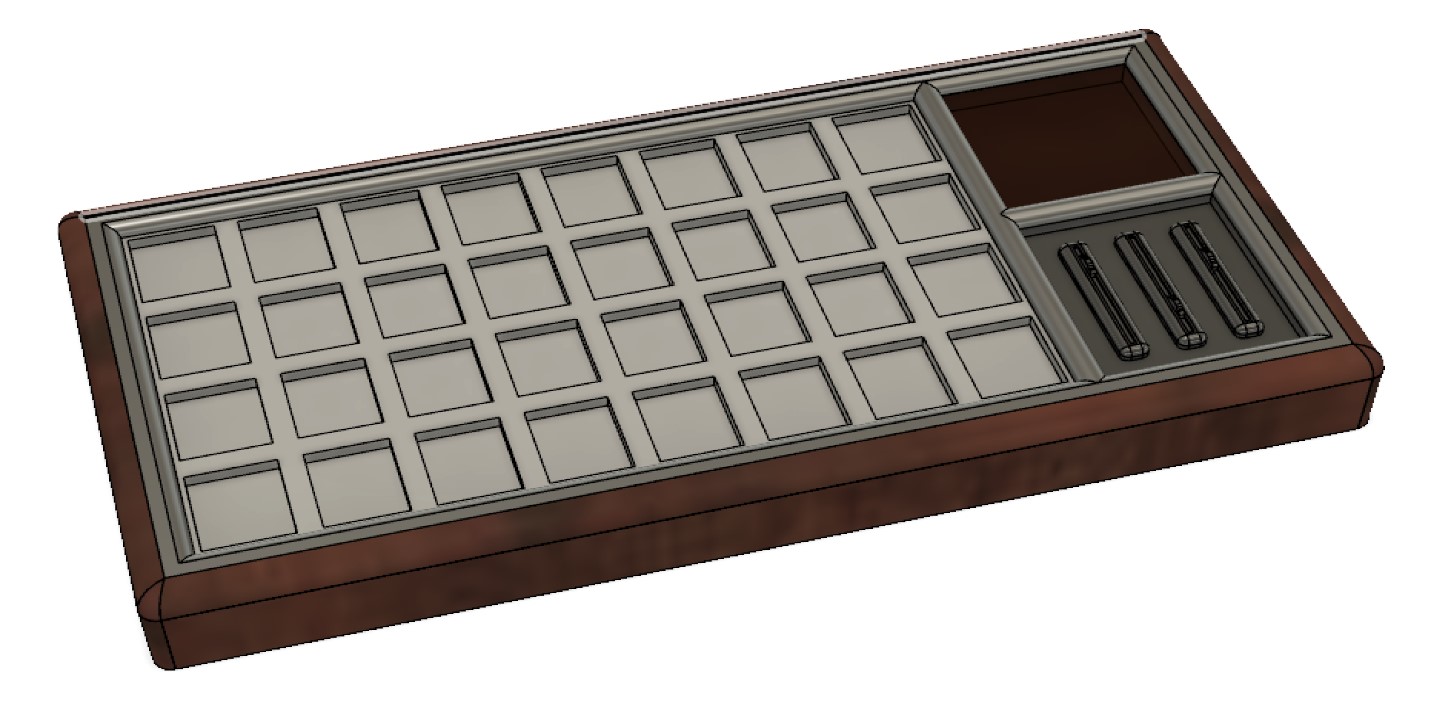
Then, finally, I made the “pixel” array as well as the potentiometers.
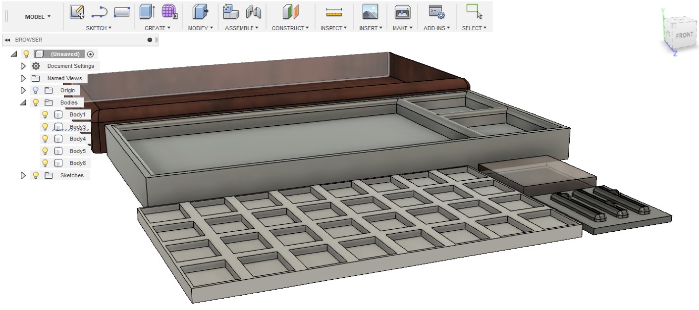
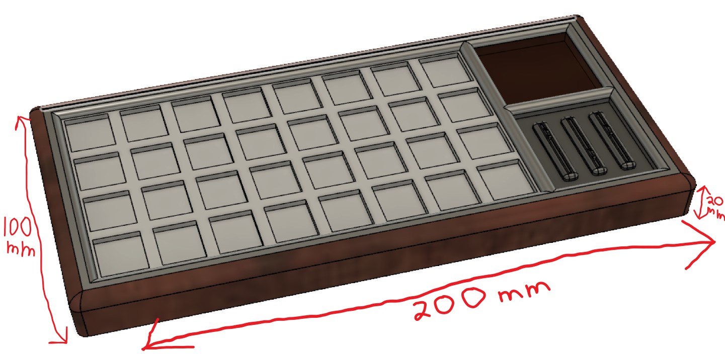
Each of the pieces I have made will fit together to nicely represent my final project idea below.
GrabCAD and SketchFab
Throughout this course, I’d like to be able to embed my 3D models directly onto my webpage so that viewers can easily interact with them. I wanted to give GrabCAD a shot at this, but after creating an account and getting models uploaded, I wasn’t able to find any sort of embed feature. I’ll still keep up my GrabCAD account for future use incase it does become necessary to have, but for now I’m going to stick with Sketchfab for embedding my models. I created a SketchFab account after seeing that it has an exceedingly easy to use embed feature, as well as that it lets you change the starting viewpoint of your embedded models with ease.
FreeCAD
FreeCAD was a bit of a reality check for me. I’ve been using fusion and corel for quite a while now, so I’m very familiar with how to use them and where the buttons are in the interface, but FreeCAD was quite different.
Maker Coin
I started out in FreeCAD by just making my own basic Maker Coin to help me figure things out. One thing that I immediately noticed about freecad Is that it considers the XY plane as the “Base” of the object which means that when you extrude a sketch it pulls along the Z plane towards you. The way I’m used to it, the XZ plane is usually the base so that you can extrude upwards along the Y axis. When I saw this, I realized my misunderstanding.
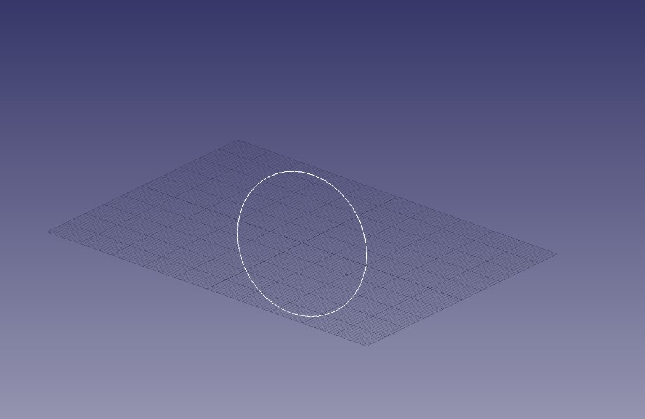
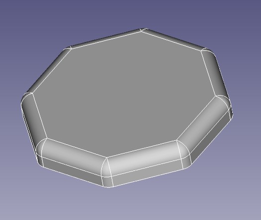
It took about 30 minutes of just trial and error to get to this point, you can start to see the shape of my coin coming through.
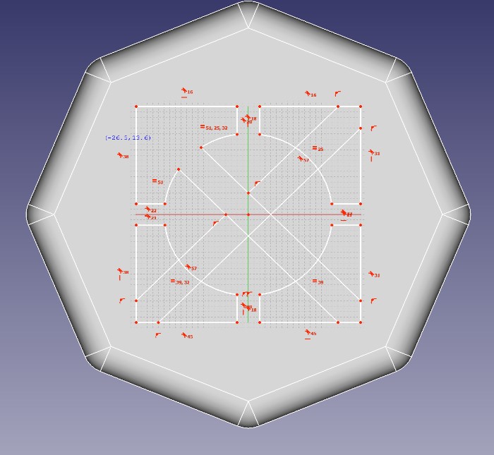
Here’s a sketch of the design on the front of the coin in progress.
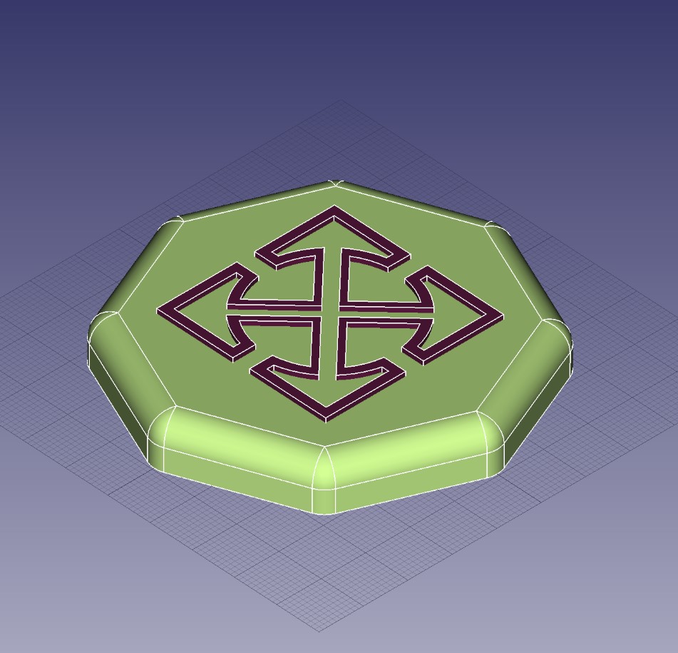
After some more time (and a bit of frustration) I did manage to get the design to extrude outwards, but I couldn’t get much further than that. Usually I do like to incorporate more design into my coins, but this will do for now. Plus, this was a good start at getting me used to the basics of FreeCAD, and from here at least I’ll kindof know what I’m doing.
Final Project Model
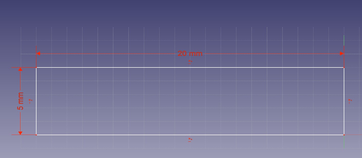
At this point, I’m beginning to realize that I’ll need more outside help than the quick instructional video that Niel provided earlier. While it was certainly helpful for getting going, I’ll need a bit more guidance to really be effective in this CAD. I found this guide on the FreeCAD wiki that helped me get going. The first thing I did was set up the basic shape of my box and extrude it outwards.
After getting the basic shape set up, I then began to apply external features to it.
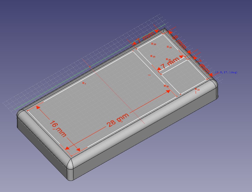
I’m starting to realize where my confusion was coming from last night. I was making the right shapes and doing the right things, I just wasn’t doing any of it in order. Now that I’m starting to come to understand the flow of procedures when designing a part, things are going better.
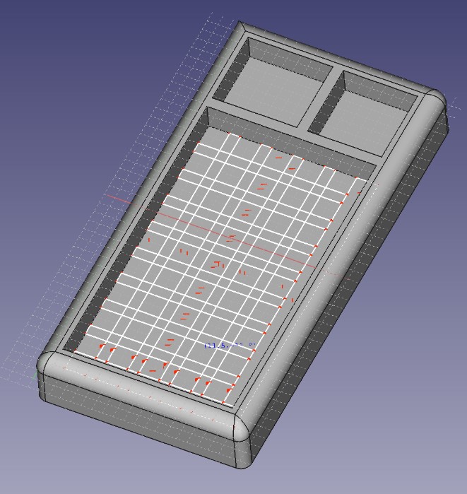
I extruded spaces for the parts, then I made the sketch for the internals.
So everything was going well, until this happened…
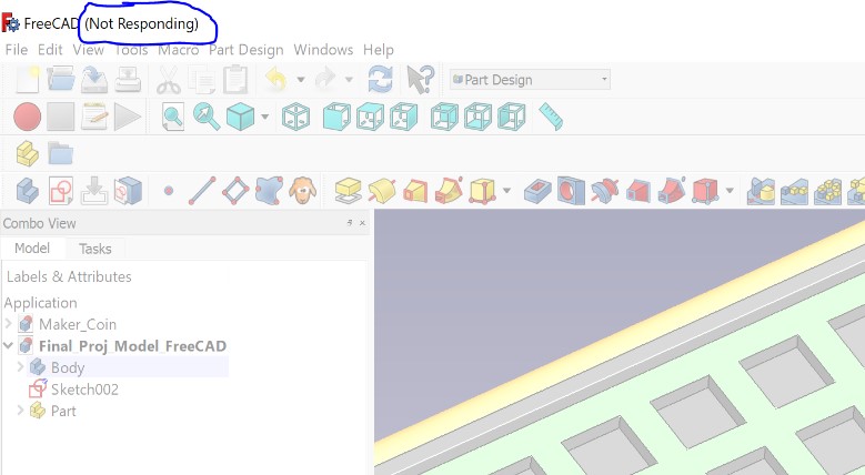
I restarted FreeCAD and when I opened up the recovery files all I got was this.
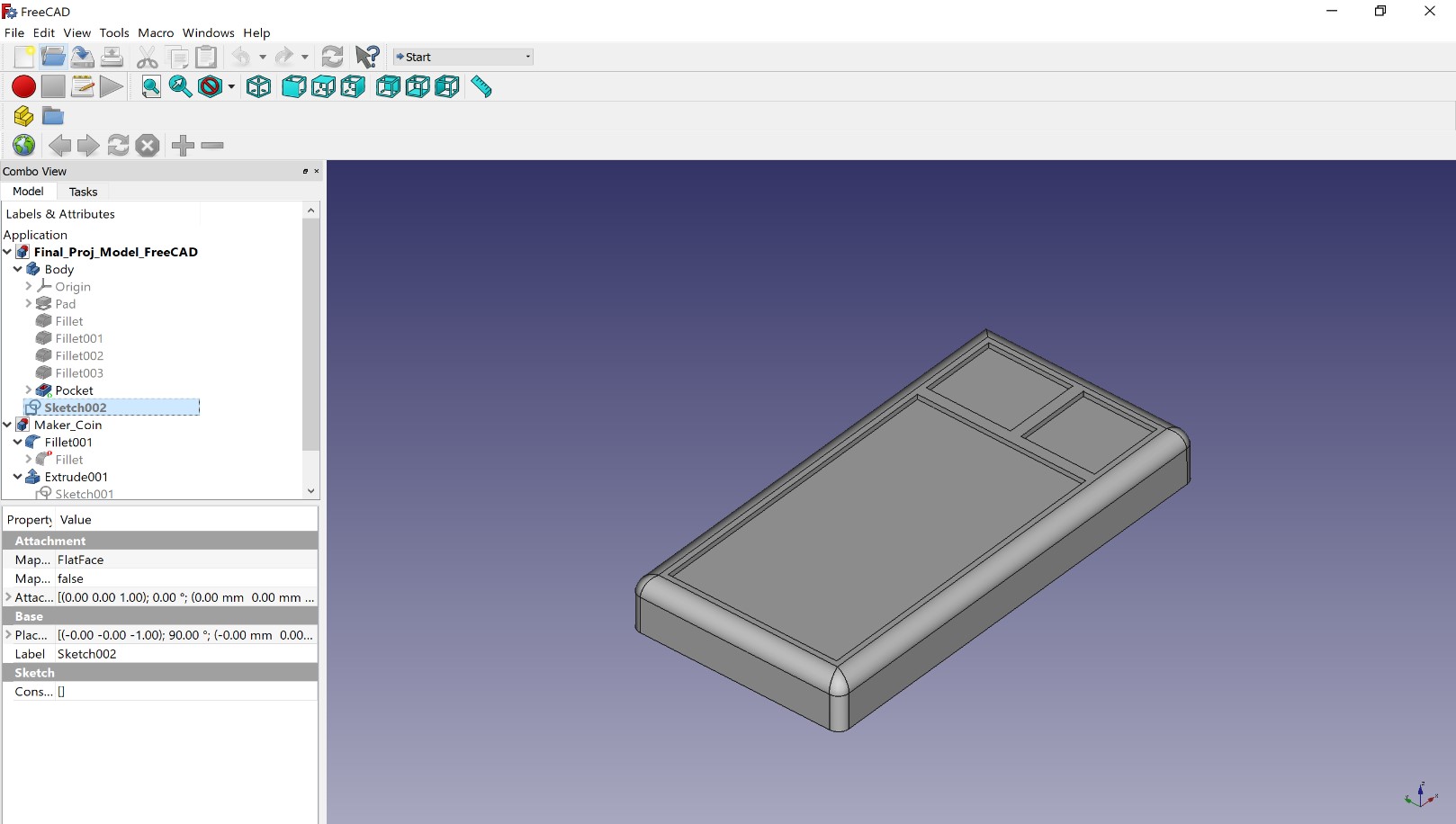
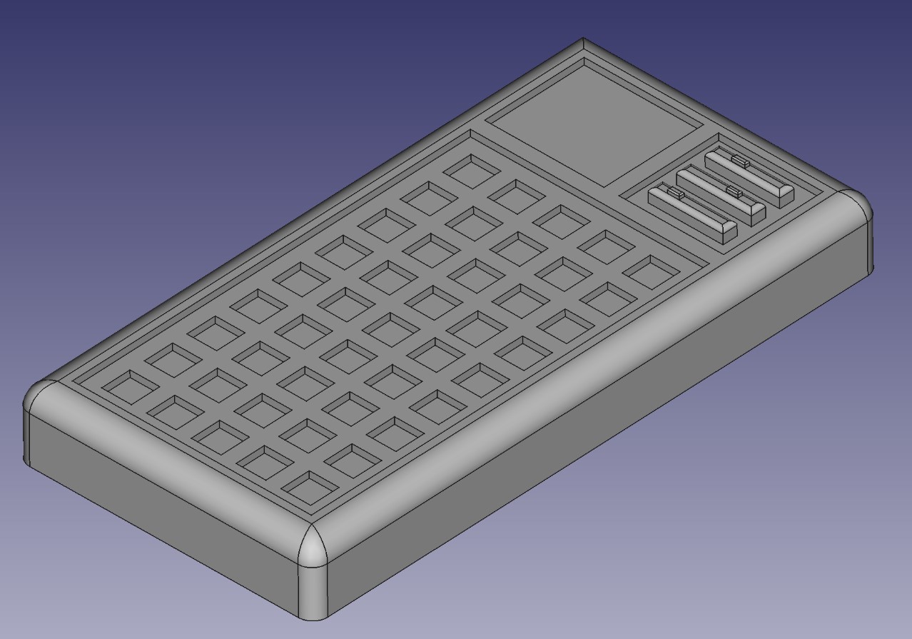
This was pretty frustrating, but I did manage to redo that portion of my work and I ended up with this as my final result.
At this point I certainly feel more comfortable using FreeCAD, and I definitely see how it could be a valuable CAD tool to some people out there, but I don’t feel like FreeCAD would really work for me in the long term. Fusion 360 still feels so much more intuitive whereas FreeCAD seems to be very procedural, which I don’t enjoy as much.
Generative design
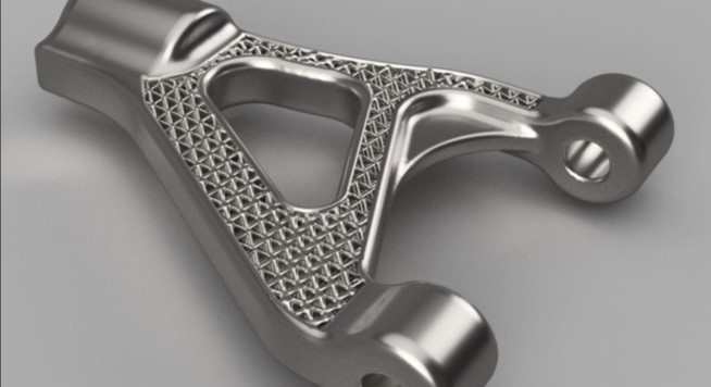
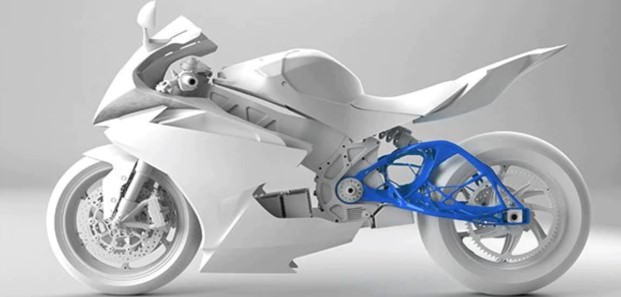
Generative design was the last thing that I looked into this week, but unfortunately I discovered that at least for now, I won’t have the opportunity to work with it. Generative design is a really cool concept that I still don’t entirely understand, but from what I could gather when looking around online, it seems like a more intelligent way to design project parts that use less material and often have otherworldly looking aspects to them. It grabbed my attention at first just because of how crazy and unique it looked, and it kept my attention due to the many real world applications that can come out of it.
Here are some examples of what I’m talking about. I found all of these on google images, and if you just want to go browse more crazy looking stuff like I did at first, click this link.
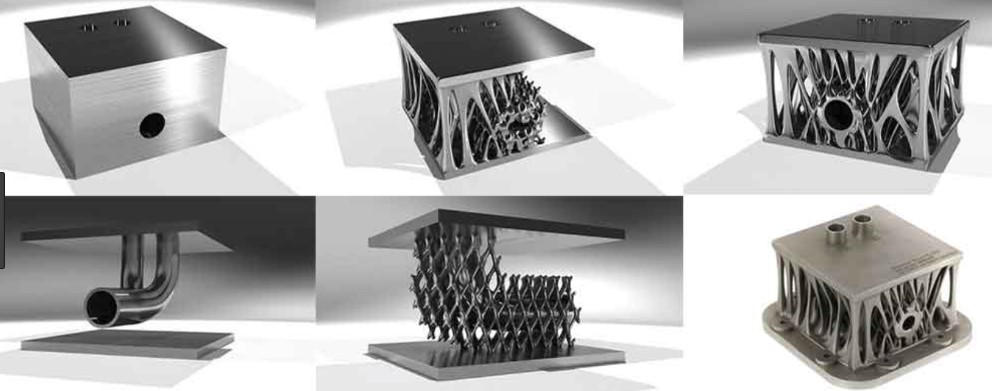
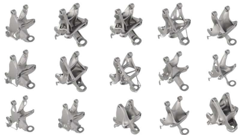
Basically, here’s how generative design actually works. With any 3D design tool at all, you would expect that someone had to go in and tell the computer where they wanted material to be, and in most cases you would be right. Generative design is different though, rather than deciding where specifically you want the material to be, you have to lay out parameters for where the computer shouldn’t generate material at all, and then you have to add in the few key areas that must be solid for the project to work. After that, you sort of just let the software run loose and do what it’s supposed to. It will create tons of different versions of the same part, and you can narrow down your selection based on certain needs such as strength, volume, and stability. Here’s an example of what all of those separate versions may look like before any are culled out.
Generative design seems like a really cool concept to get into and learn about, but it just isnt accesible at a consumer or student level yet. Due to all of the models that have to be created for generative design to work, and all of the parameters that go into each of those models specifically, the raw computational power required to let tons of inventors around the globe get into this new frontier of design just isn’t there yet. Until computers are able to handle these requirements it won’t be possible to get this out to the general public.
3D Models
Here are all of my files from this week.