INPUT DEVICES
11.WEEK
Finally are this weeks, weeks of inputs and outputs. I was waiting for them like a little kid. At the beginning of fabacademy I thought I would never program microcontroller boards and look at me now. Well not yet, after this assignment.
So for this weeks individual assignment wee need to make our own board that is more likely arduino. On lecture and in instructions there are two persons from past year’s of fabacademy that contributed to this assignment. Those people are FABKIT, SATSHAKIT . I connected names to their direct sites so you can check them out, if you are new to this world it’s going to be from big help.
After we make one board we need to decide which sensors are we going to test. For me it would be great if I test some sensors for my final project so I can be prepared and make it again without some bigger errors.
And for group assignment need to test devices analogue levels and digital signals. For that part I’ll use oscilloscope at my colleagues fablab DEZENTRALE.
INDIVIDUAL ASSIGNMNET
BOARD DESIGNE
First is to make a board so lets open Eagle first. Through this part I’ll be a little shorter and if you want to see detailed explanations on what you have to do and how in my week5 assignment.
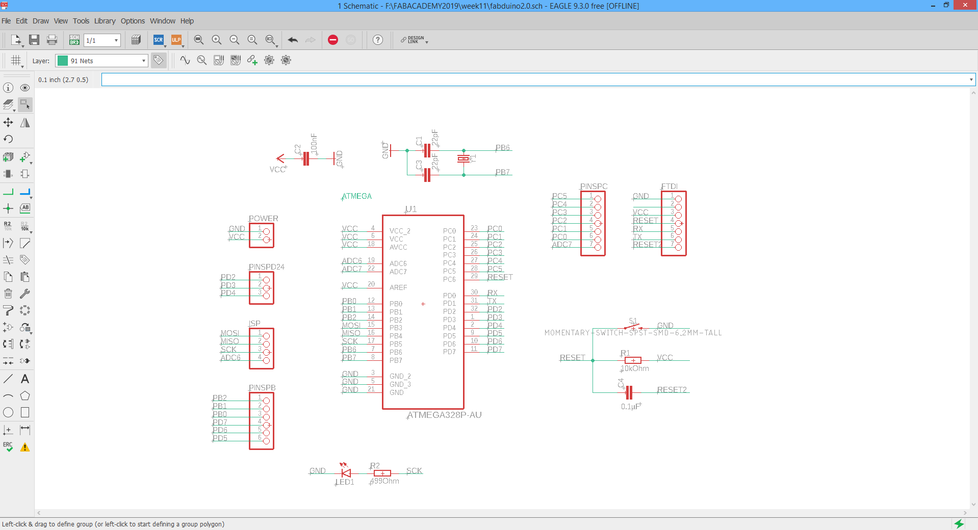
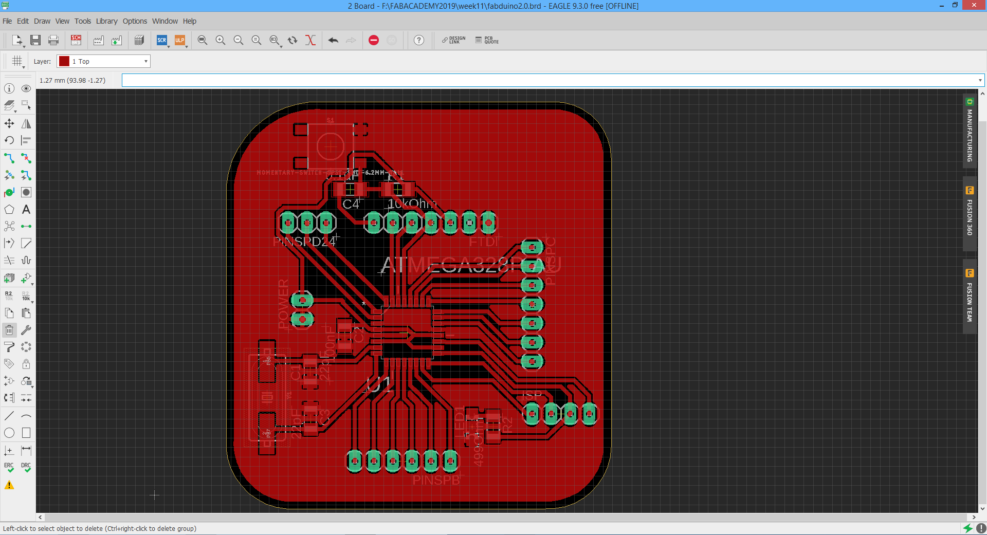
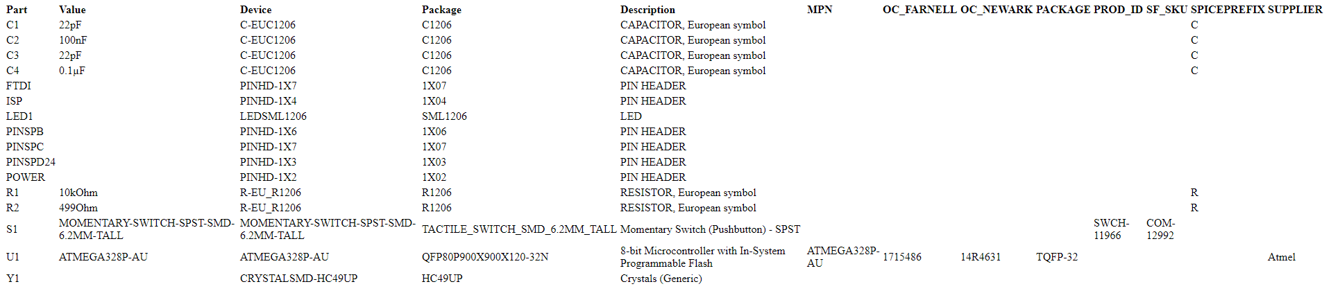
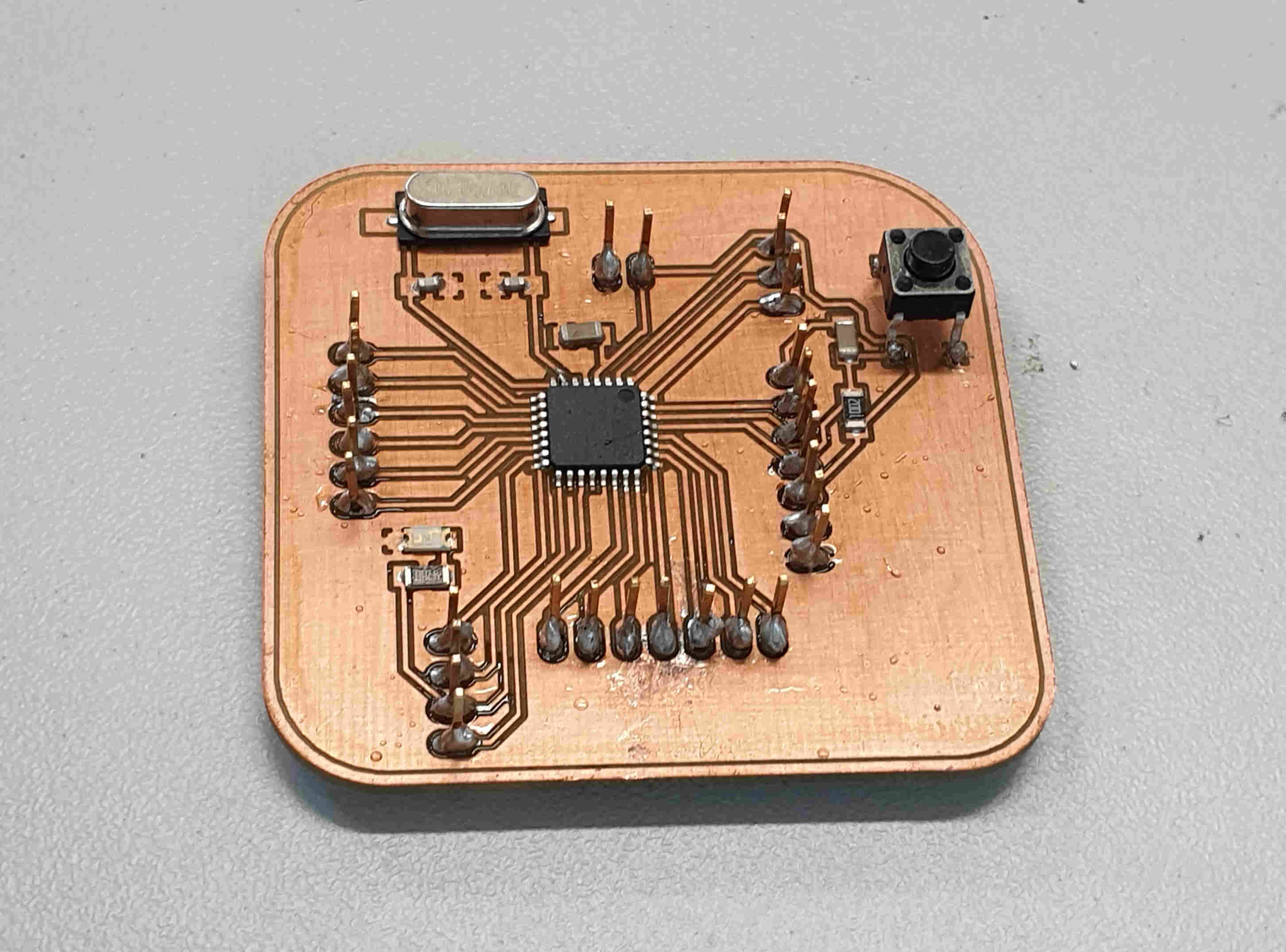
This is schamatic and board view of my "valentino" board, needed files I'll put on the end of the site so it can be downloaded and maybe can help someone. For me this is great board also for final project because the idea is to use only arduino compatibile sensors. Below I put BOM(bill of material so it's easier to redraw the board.
When I’m satisfied with the look of the board, need to save schematics and board design to USB and plug it in to lpkfs computer to mill the board. I’m gonna also skip a little bit that part of milling, cleaning, soldering and backing, that is also in my week 5 explained. But I’ll poste below some pictures and of course in the end of page .zip files for downloading.
Next steps for making the board after EAGLE are:
1. Pripare files and parameters for milling on LPKFs computer, set mill on it's zero position.
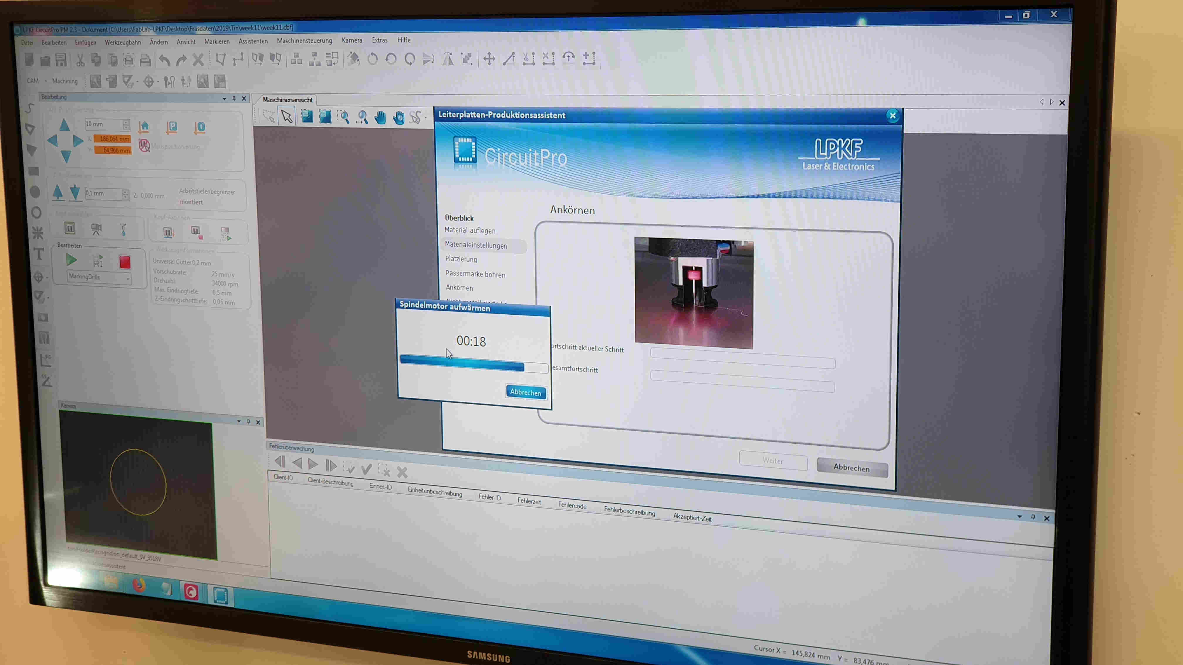
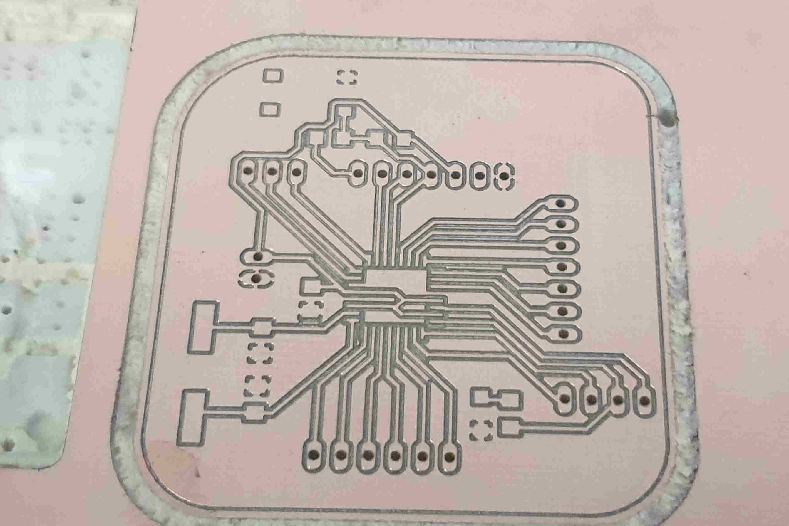
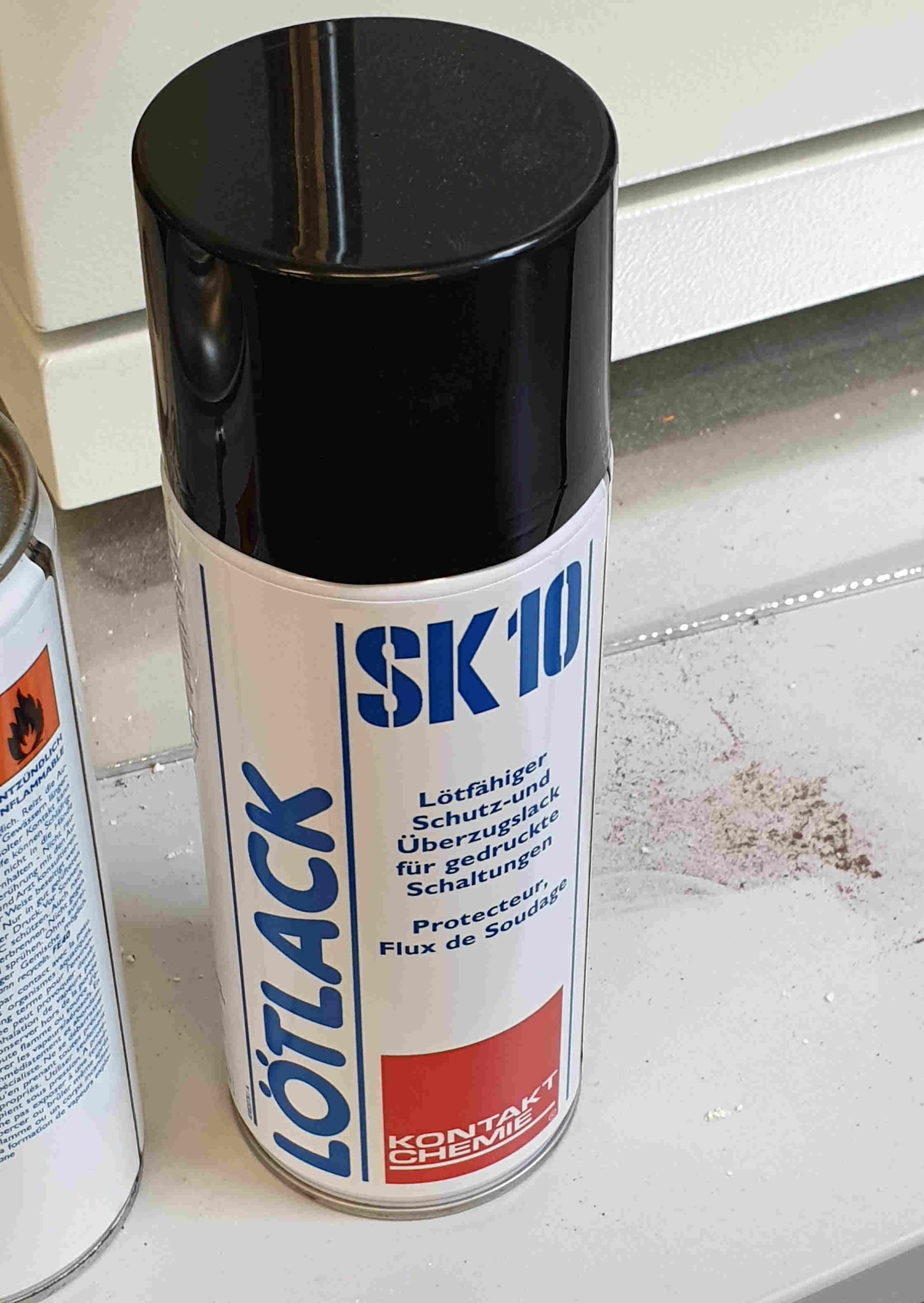
2. Now start job on mill and waite untill is done. Don't forget to always look on mill because of suden errors so you can react on time. Now when the board is done I have to clean it and spray it with SK10.
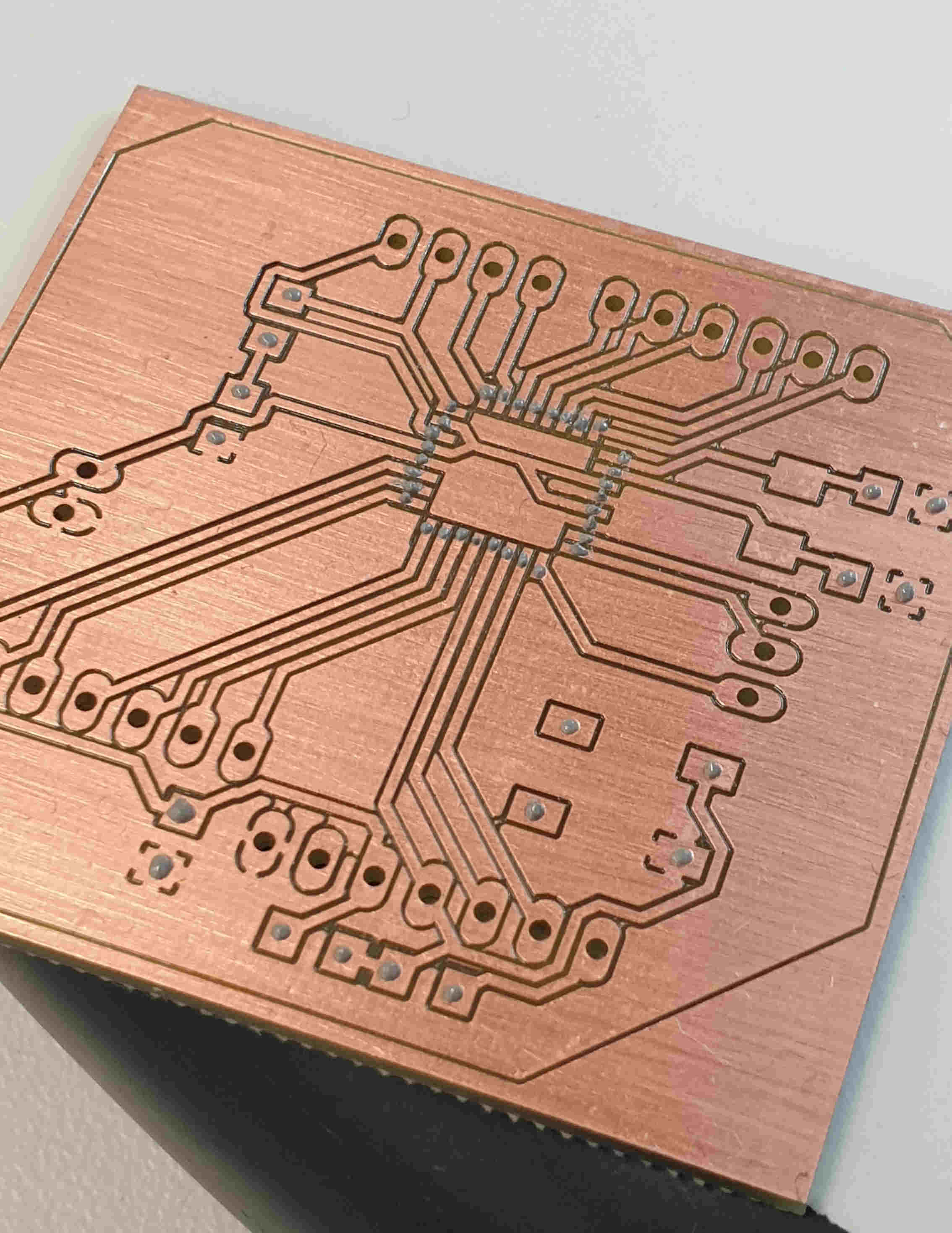
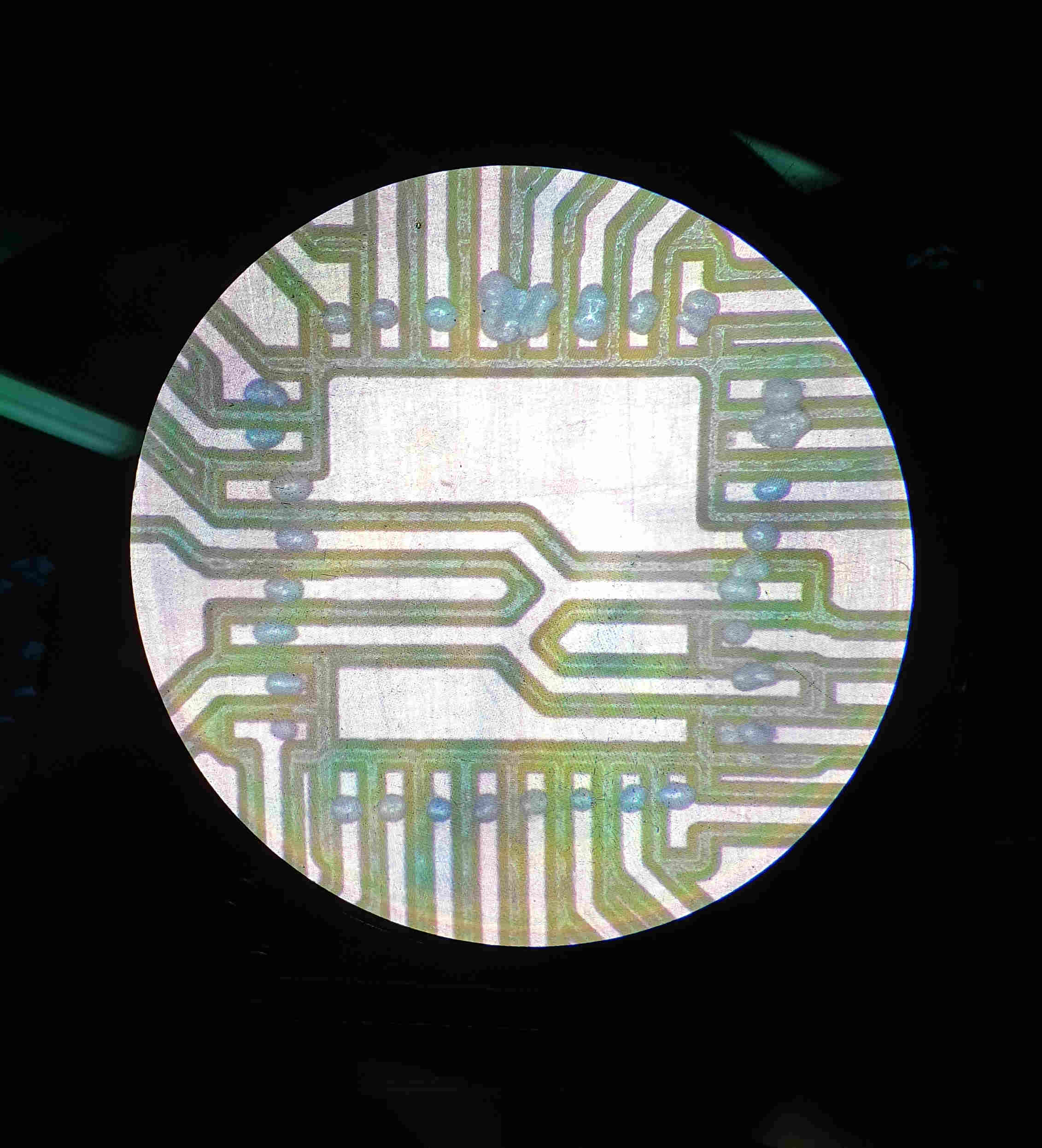
3. Using paste extruder to put solder paste on places where the components should come. This step depends on do you have pste extruder at your lab or not, if don't than is regular soldering needed.
As you can see the secon piture is showing result of my shaking and unstady hands, but that is also unexperiance. I used tiny scalpel and microscope to remove all solder paste that was extra.
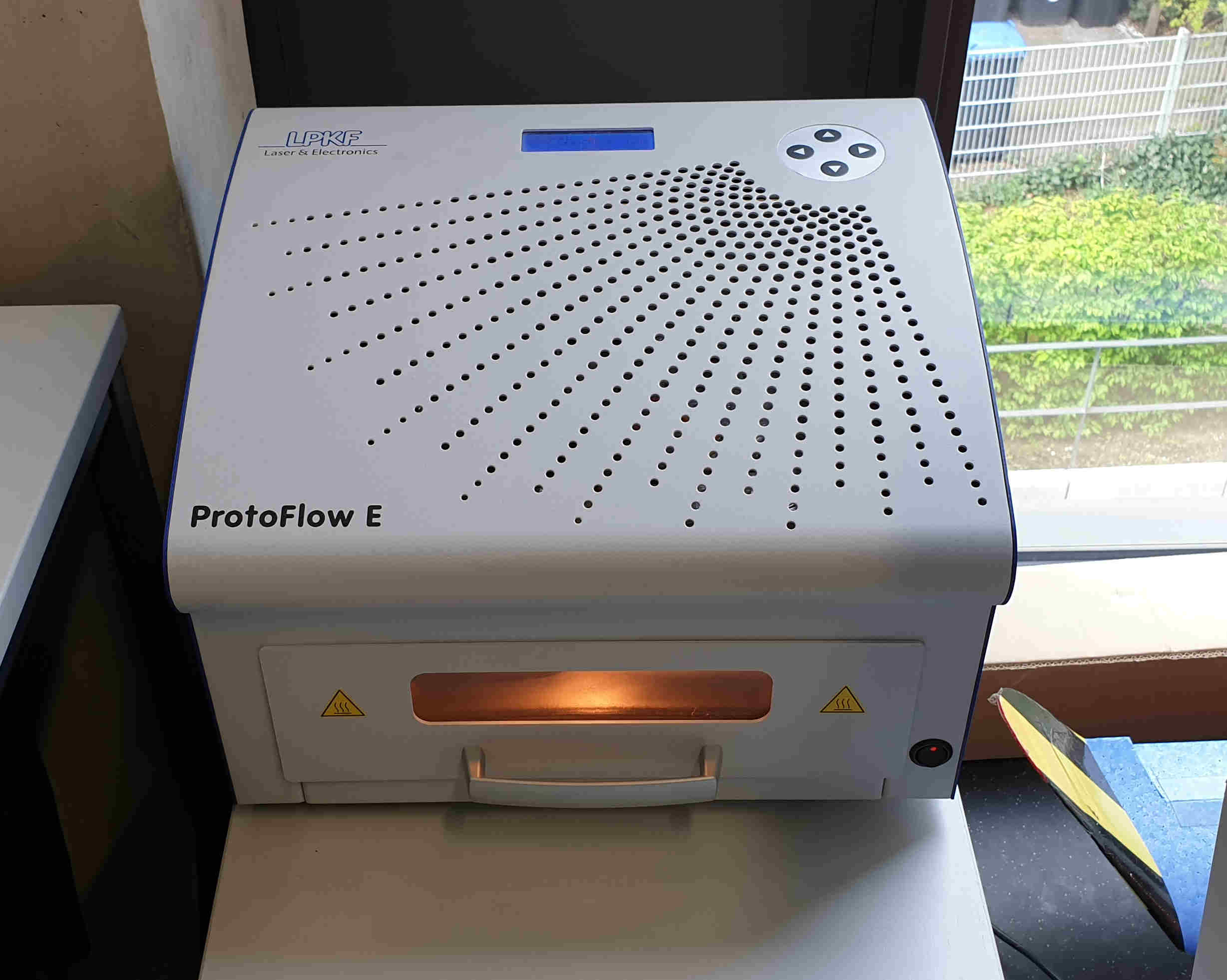
4. Then is turn to put all components on boar, this was also little bit tricki for me because of my shaking hand but somehow I did it. and after putting all components on, I need to put board in previously heatted oven. Oven makes sound when reflowing is done and the board is ready just needs to be cool down before use.
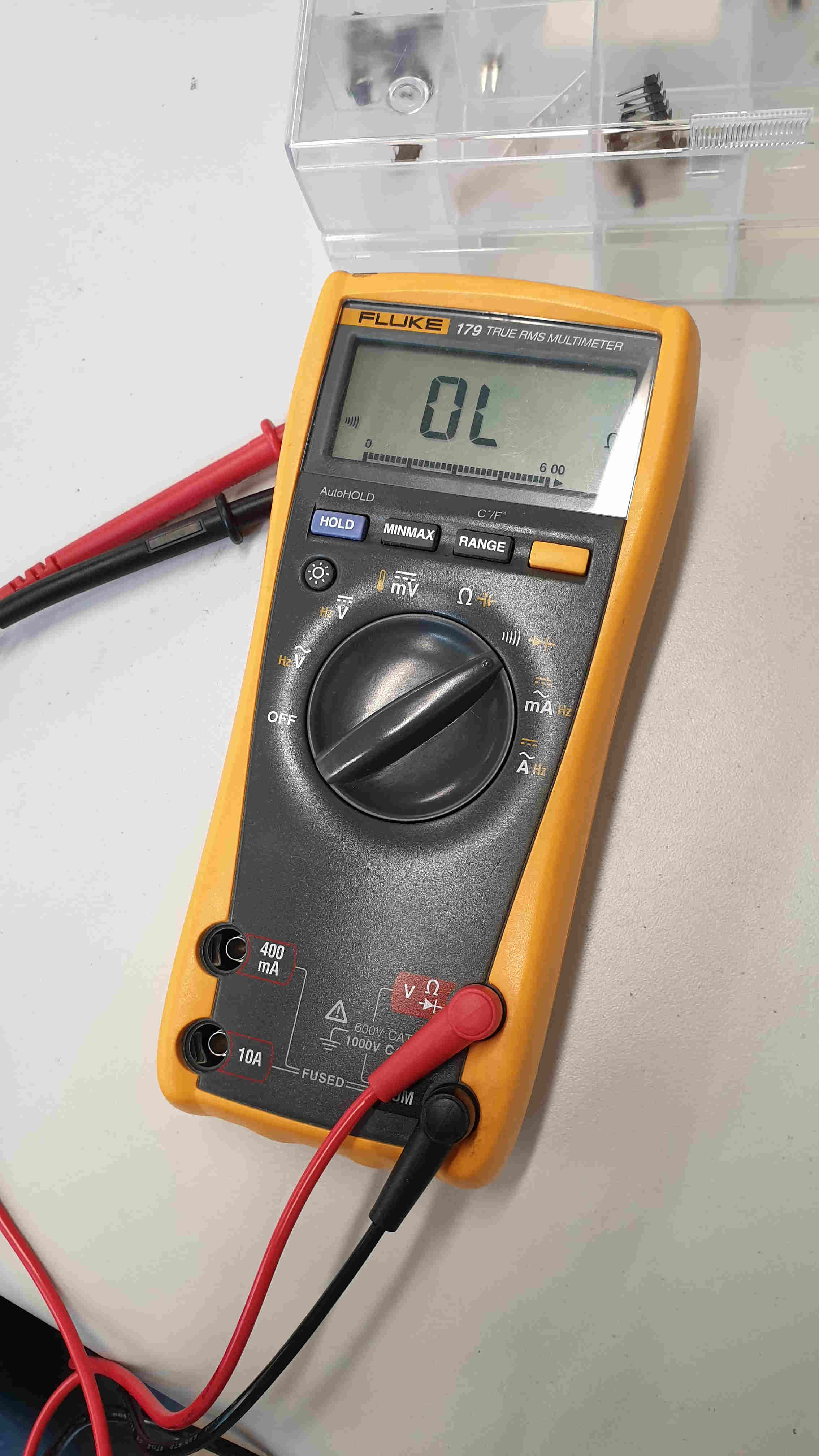
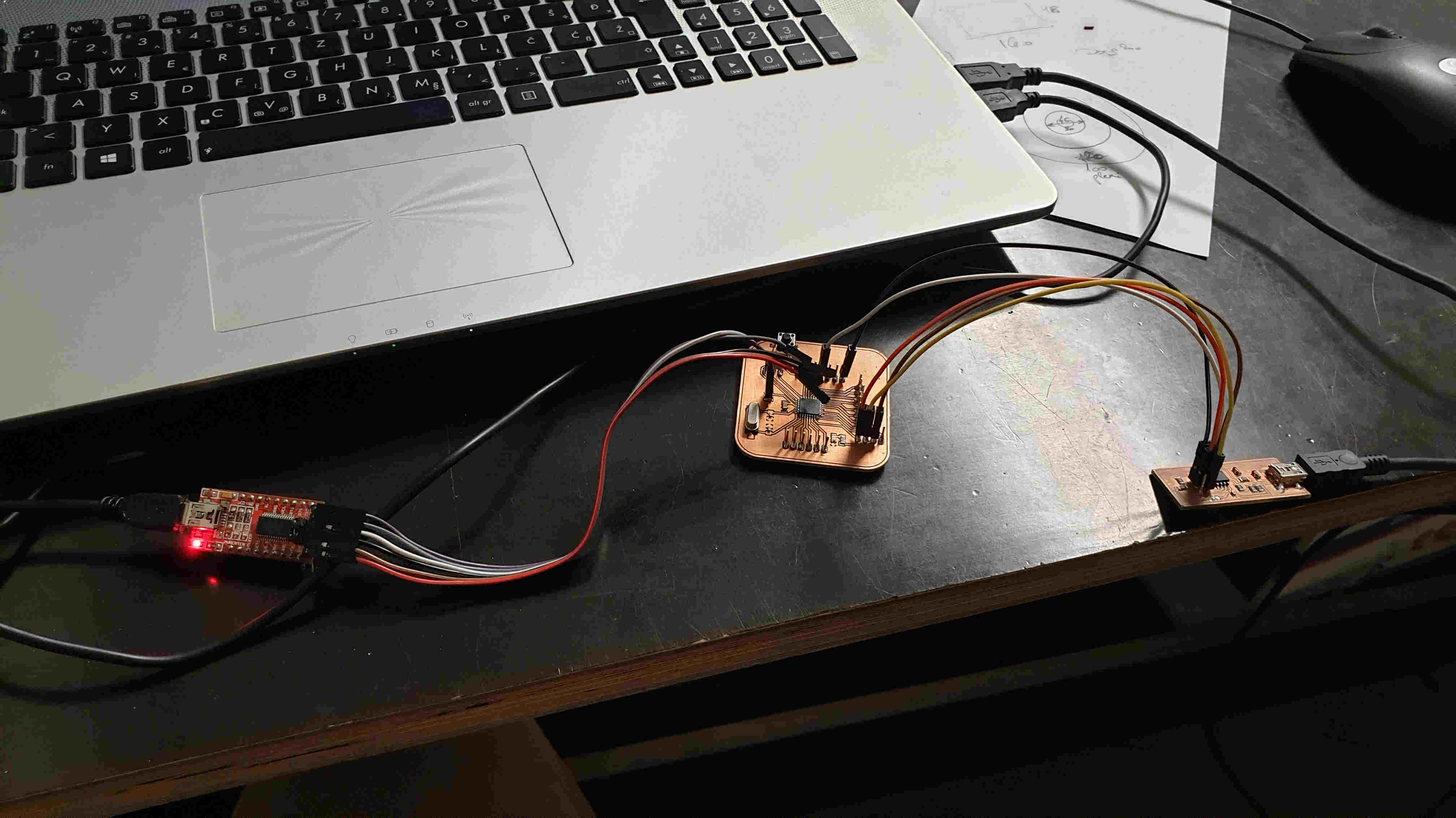
5. Last step before I can use it and test all the sensors. In previously weeks when I also needed to make PCBs I all the time forget relly important step, that's checking all connections with multimeter. This time I checked them, there were two bad connections, but after 5 minutes all was good. Now just to connect my valentino board to computer, with order of connecting ( computer>FABISP>valentino board>FTDI>computer), open Arduino IDE and run "burn bootloader", now the board is all set up for programming.
TESTING SENSORS
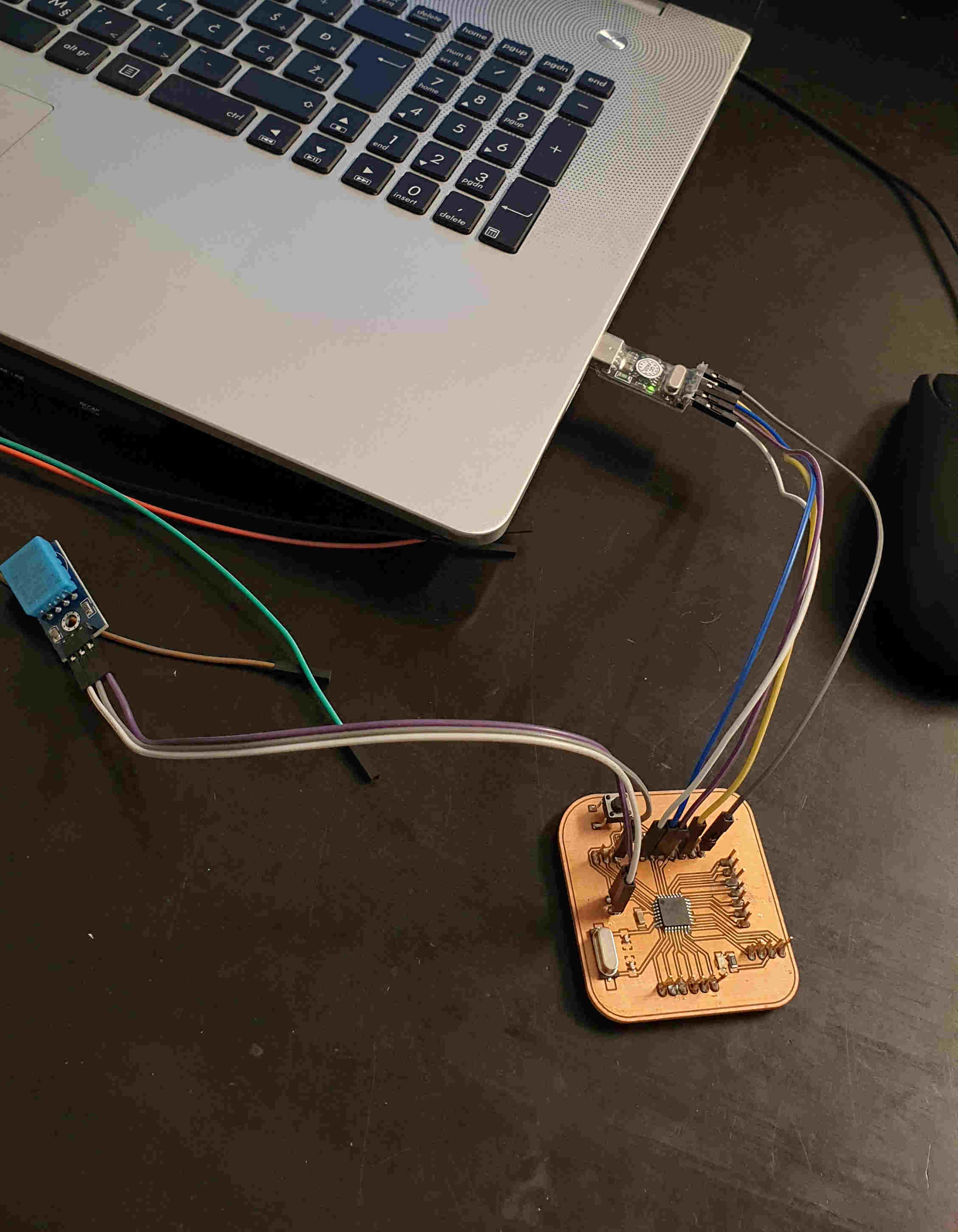
HUMIDITY AND TEMPERATURE SENSOR
The DHT11 detects water vapor by measuring the electrical resistance between two electrodes. The humidity sensing component is a moisture holding substrate with electrodes applied to the surface. When water vapor is absorbed by the substrate, ions are released by the substrate which increases the conductivity between the electrodes. The change in resistance between the two electrodes is proportional to the relative humidity. Higher relative humidity decreases the resistance between the electrodes, while lower relative humidity increases the resistance between the electrodes.The DHT11 measures temperature with a surface mounted NTC temperature sensor (thermistor) built into the unit.
#include <dht.h>

dht DHT;

#define DHT11_PIN 7

void setup(){
  Serial.begin(9600);
}

void loop()
{
  int chk = DHT.read11(DHT11_PIN);
  Serial.print("Temperature = ");
  Serial.println(DHT.temperature);
  Serial.print("Humidity = ");
  Serial.println(DHT.humidity);
  delay(1000);
}
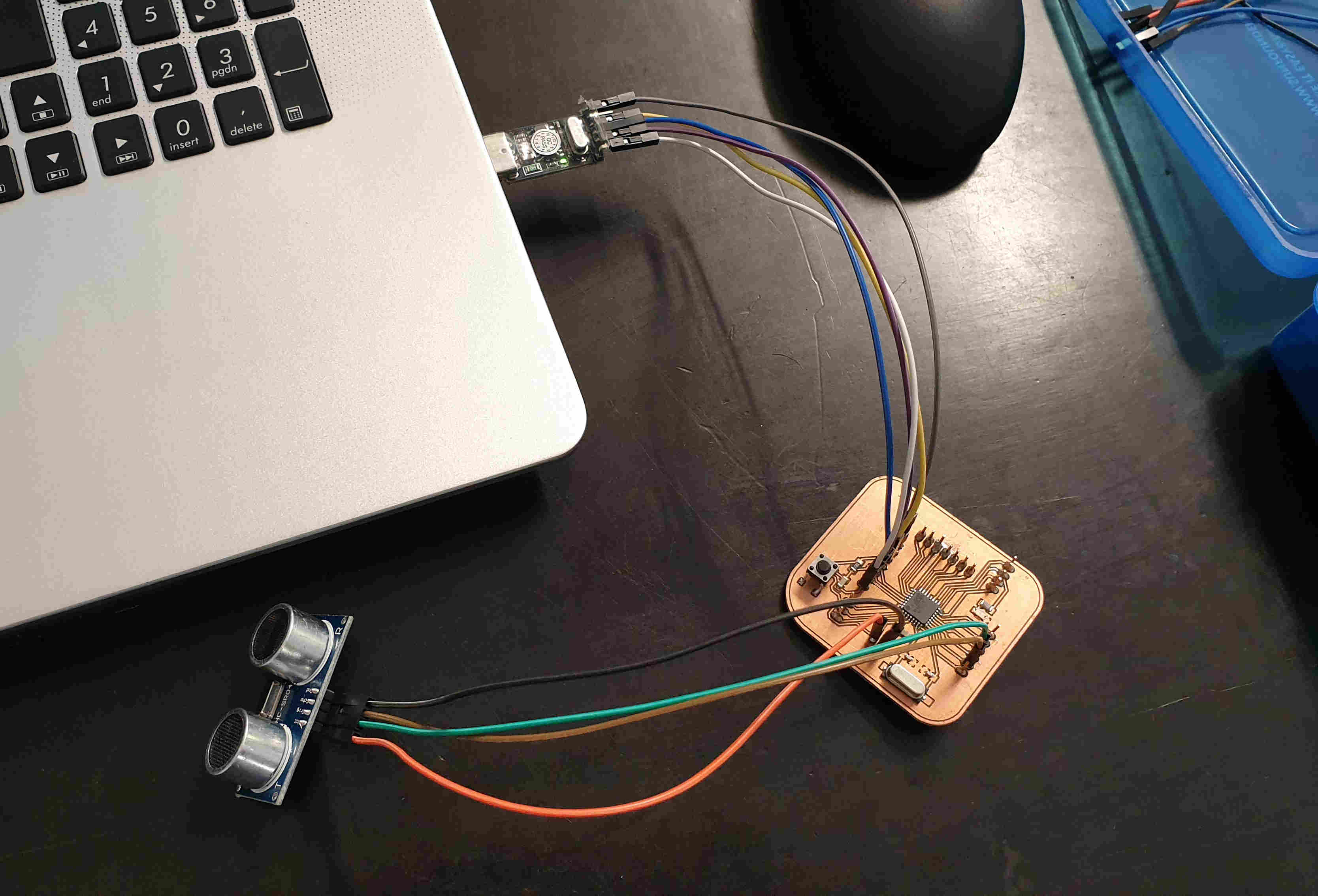
Ultrasonic sensor
The HC-SR04 ultrasonic sensor uses sonar to determine distance to an object like bats do. It offers excellent non-contact range detection with high accuracy and stable readings in an easy-to-use package. It comes complete with ultrasonic transmitter and receiver modules.
The ultrasonic sensor uses sonar to determine the distance to an object. Here’s what happens:The transmitter (trig pin) sends a signal: a high-frequency sound.When the signal finds an object, it is reflected and…the transmitter (echo pin) receives it.
The time between the transmission and reception of the signal allows us to calculate the distance to an object. This is possible because we know the sound’s velocity in the air.
/*
 * created by Rui Santos, https://randomnerdtutorials.com
 *
 * Complete Guide for Ultrasonic Sensor HC-SR04
 *
    Ultrasonic sensor Pins:
        VCC: +5VDC
        Trig : Trigger (INPUT) - Pin11
        Echo: Echo (OUTPUT) - Pin 12
        GND: GND
 */

int trigPin = 11;    // Trigger
int echoPin = 12;    // Echo
long duration, cm, inches;

void setup() {
  //Serial Port begin
  Serial.begin (9600);
  //Define inputs and outputs
  pinMode(trigPin, OUTPUT);
  pinMode(echoPin, INPUT);
}

void loop() {
  // The sensor is triggered by a HIGH pulse of 10 or more microseconds.
  // Give a short LOW pulse beforehand to ensure a clean HIGH pulse:
  digitalWrite(trigPin, LOW);
  delayMicroseconds(5);
  digitalWrite(trigPin, HIGH);
  delayMicroseconds(10);
  digitalWrite(trigPin, LOW);

  // Read the signal from the sensor: a HIGH pulse whose
  // duration is the time (in microseconds) from the sending
  // of the ping to the reception of its echo off of an object.
  pinMode(echoPin, INPUT);
  duration = pulseIn(echoPin, HIGH);

  // Convert the time into a distance
  cm = (duration/2) / 29.1;     // Divide by 29.1 or multiply by 0.0343
  inches = (duration/2) / 74;   // Divide by 74 or multiply by 0.0135

  Serial.print(inches);
  Serial.print("in, ");
  Serial.print(cm);
  Serial.print("cm");
  Serial.println();

  delay(250);
}
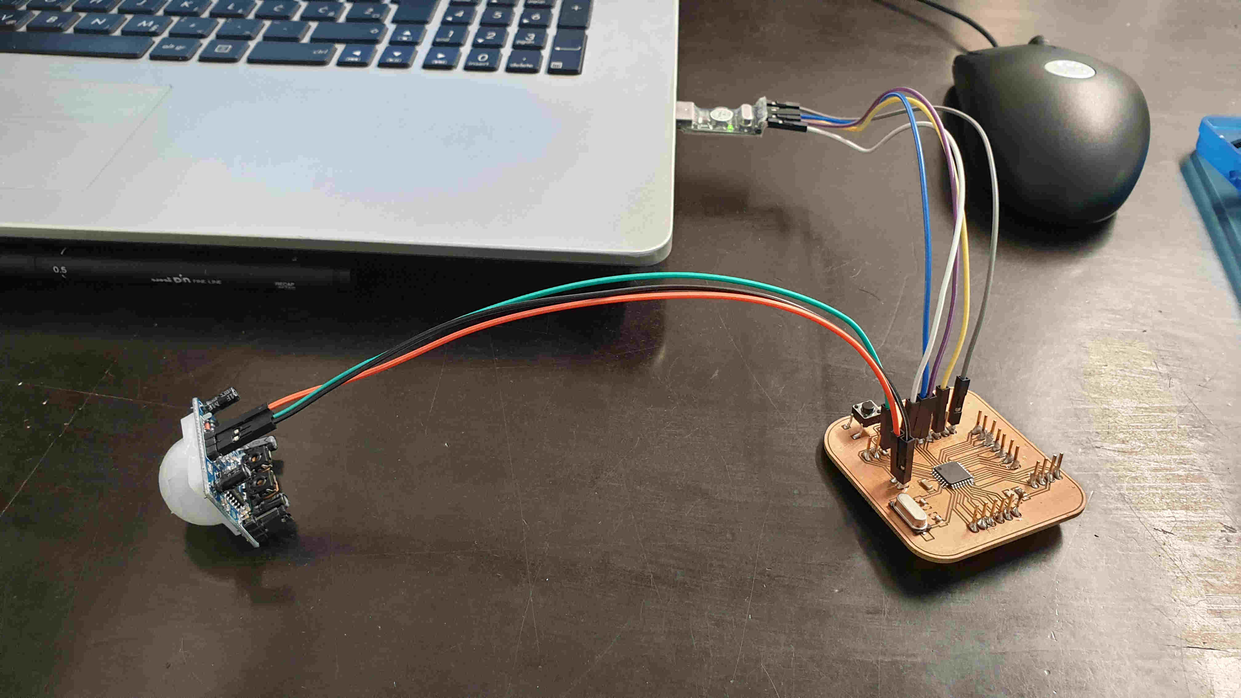
PIR SENSOR
The PIR motion sensor is ideal to detect movement. PIR stand for “Passive Infrared”. Basically, the PIR motion sensor measures infrared light from objects in its field of view.So, it can detect motion based on changes in infrared light in the environment. It is ideal to detect if a human has moved in or out of the sensor range.Has two built-in potentiometers to adjust the delay time
/*
    Arduino with PIR motion sensor
    For complete project details, visit: http://RandomNerdTutorials.com/pirsensor
    Modified by Rui Santos based on PIR sensor by Limor Fried
*/

int led = 13;                // the pin that the LED is atteched to
int sensor = 2;              // the pin that the sensor is atteched to
int state = LOW;             // by default, no motion detected
int val = 0;                 // variable to store the sensor status (value)

void setup() {
  pinMode(led, OUTPUT);      // initalize LED as an output
  pinMode(sensor, INPUT);    // initialize sensor as an input
  Serial.begin(9600);        // initialize serial
}

void loop(){
  val = digitalRead(sensor);   // read sensor value
  if (val == HIGH) {           // check if the sensor is HIGH
    digitalWrite(led, HIGH);   // turn LED ON
    delay(100);                // delay 100 milliseconds

    if (state == LOW) {
      Serial.println("Motion detected!");
      state = HIGH;       // update variable state to HIGH
    }
  }
  else {
      digitalWrite(led, LOW); // turn LED OFF
      delay(200);             // delay 200 milliseconds

      if (state == HIGH){
        Serial.println("Motion stopped!");
        state = LOW;       // update variable state to LOW
    }
  }
}