13 - Networking and Communications
This week's assignemnt is a very importnat assignment for my final project, so I decided to try to create the system that the final project will use. We need to create 2 boards and make them communicate between them. After doing some research and some tests, I decided to design a little board that will be used in each fret with four buttons and four LED's, one for each string. When acting as the student Ukulele, the lights will show the position of the teachers fingers with the LED's, and the one from the teacher will detect the pressure with the buttons.
How will all the boards of the Ukulele communicate?
As they are all in the same device, the best way to connect them is by a fisical communication using wires, so I decided to create an I2C communication. The idea of this boards is to send the information of the buttons as inputs or to read the information and show it in the LED's as outputs.
I2C communication
I2C is a communication bus created by Phillips back in the early 80's. It is a synchronous serial computer bus able to comunicate a huge ammount of devices as master and slave, up to 120 devices aproximatelly. It is a physical connexion that uses 4 wires, the VCC and the GND to power all the devices and to ports, the SDA and the SCL. SDA is the one in charge to transmit the data, while the SCL is the clock of the signal.
The idea is simple, the master device sends and recive data to and from the slaves, each slave has an specific address used by the master to establish communication with each one of them. When the master wants to communicate with one slave, it sends the address byte to let the slaves know to wich one is talking to, and then sends the message followed by a finish comunication byte.

Parts
This assignment is about testing the conncection and making 2 boards to communicate. My final project will have a lot of boards that will communicate between them, but I will start milling 3 boards, one master and two slaves, to test the communication and validate my idea of using I2C to communicate them. So, this assignment will have two parts, a master board and a slave board.
- Master Board: This board will have the ISP communication port to program the board and to make the I2C communication with the SCK pin as SCL and MOSI pin as SDA. Also, it will have an FTDI connection to communicate via serial port with the computer.
- Slave Board: There will we more than one slave boards. They have the ISP connection to program it and to communicate with the master. Then it will use 4 buttons and 4 LED's connected to 4 pins (one button and LED for each pin). The idea is to use the LED as a pull down resistor for the button so we will be able to use the pins as outputs lighting the LED and as inputs pressing the button.
Master board
It doesn't have any visual impact to the device, but it is really important. It's function is to communicate and organize the rest of the boards. Here are the list of commponents and the drawings that I design using KiCad following the explanation I did in Week 06.
- Attiny 84
- 10kΩ as pull-up resistor
- 1uF Capacitor
- FTDI 6 pin header
- 2x3 pin header for the ISP
Crystal 20MHz


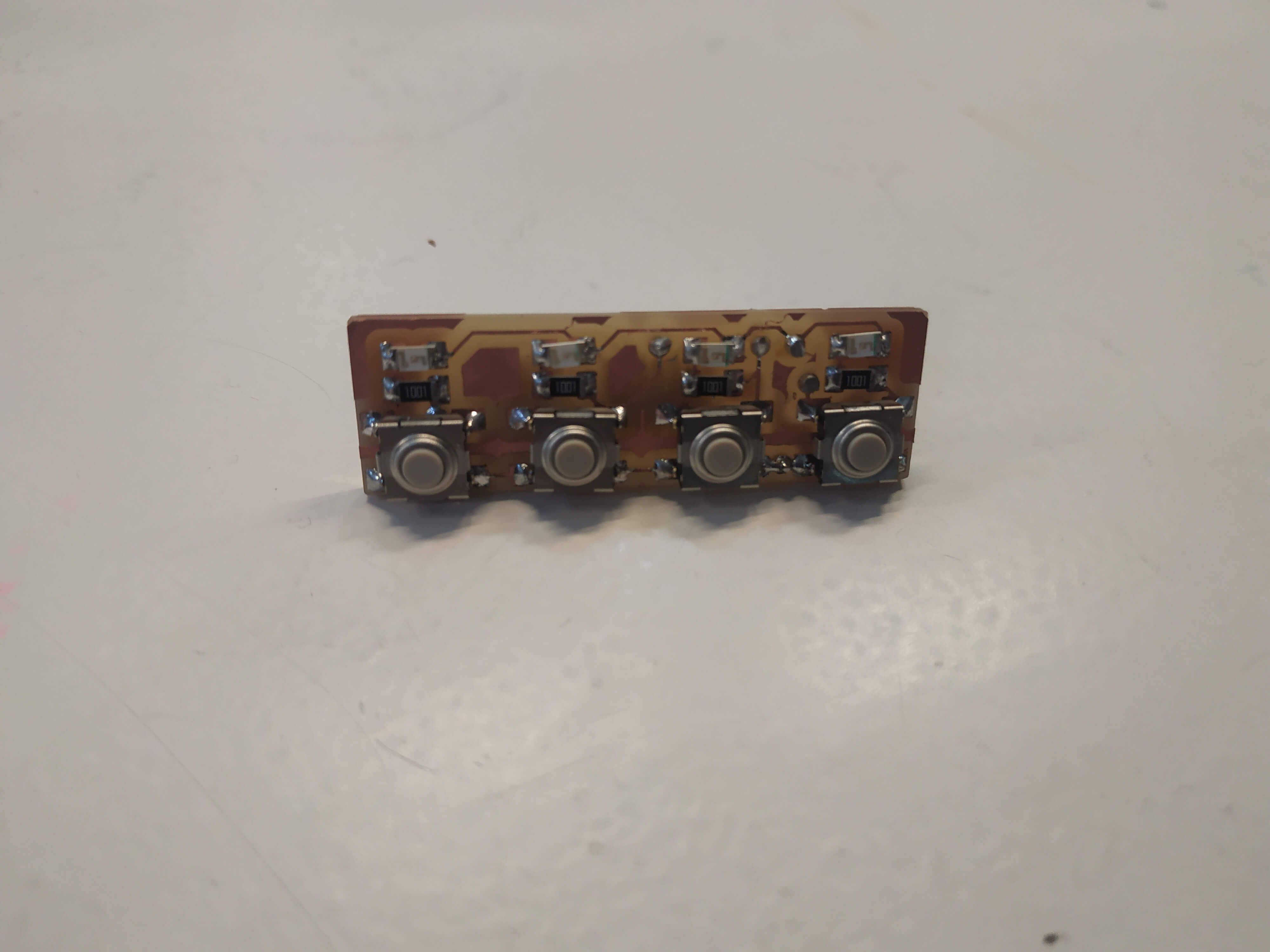
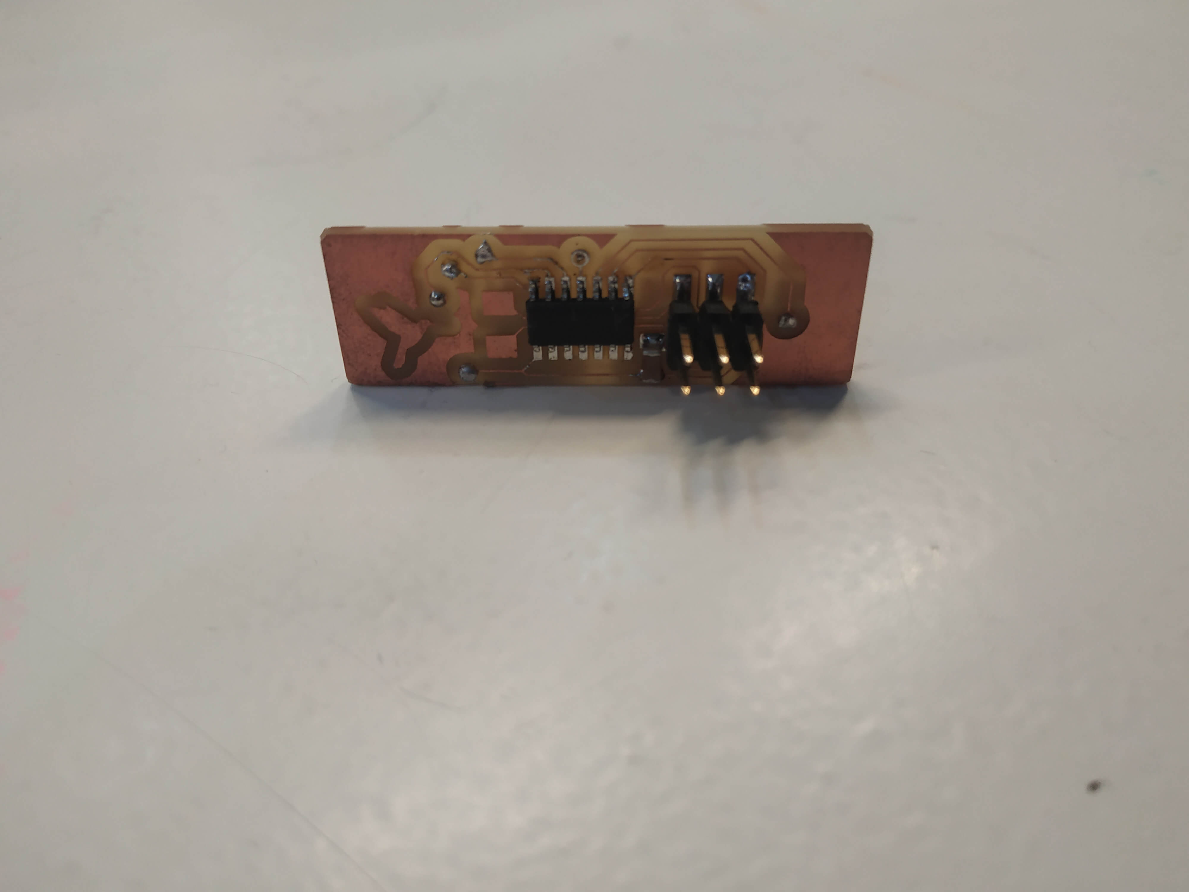
And this is the final board with all the components solded on it.
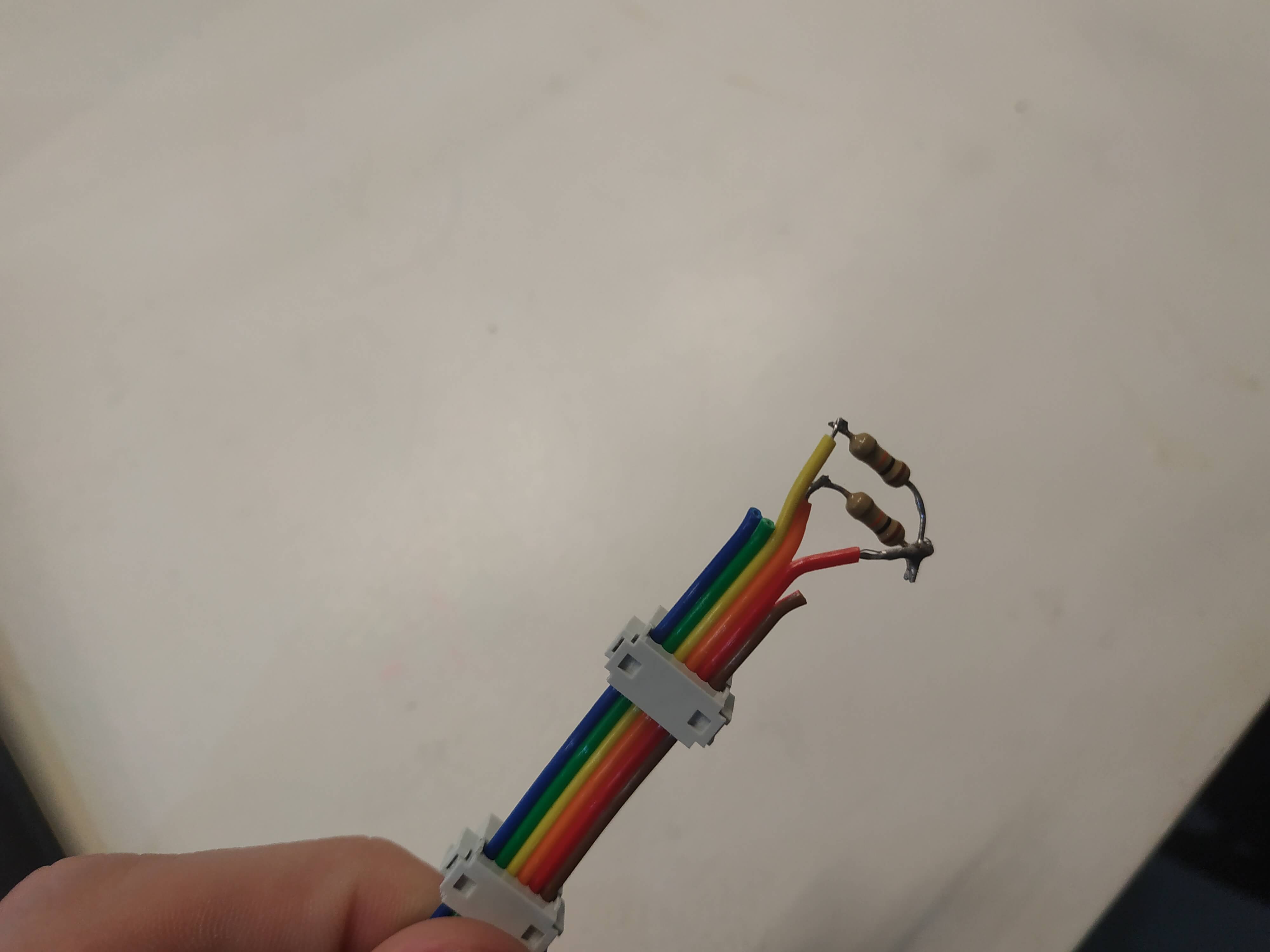
Please note that there are a couple of errors in the board. I used a 20MHz crystal, but finally I ended up working with the 8MHz internal clock of the ATtiny, so it is not needed for the board. Also, I didn't know that I would have to use pull-up resistors for the I2C bus, so they should be added. To test everything before milling a new board, I decided to solder two 10KΩ resistors in the ribbon wire directly. This resistors can be added to the master board or to one slave board.
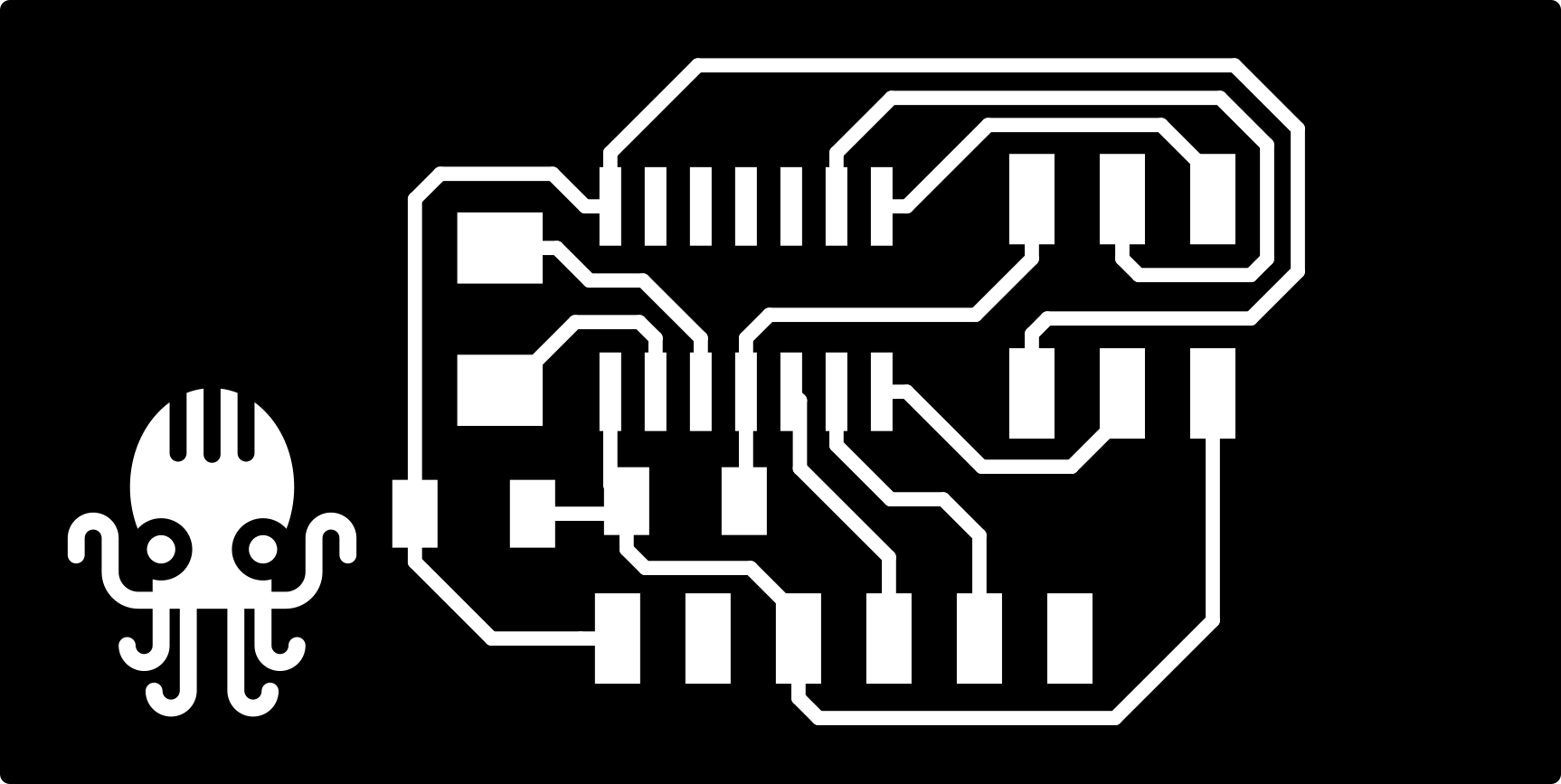
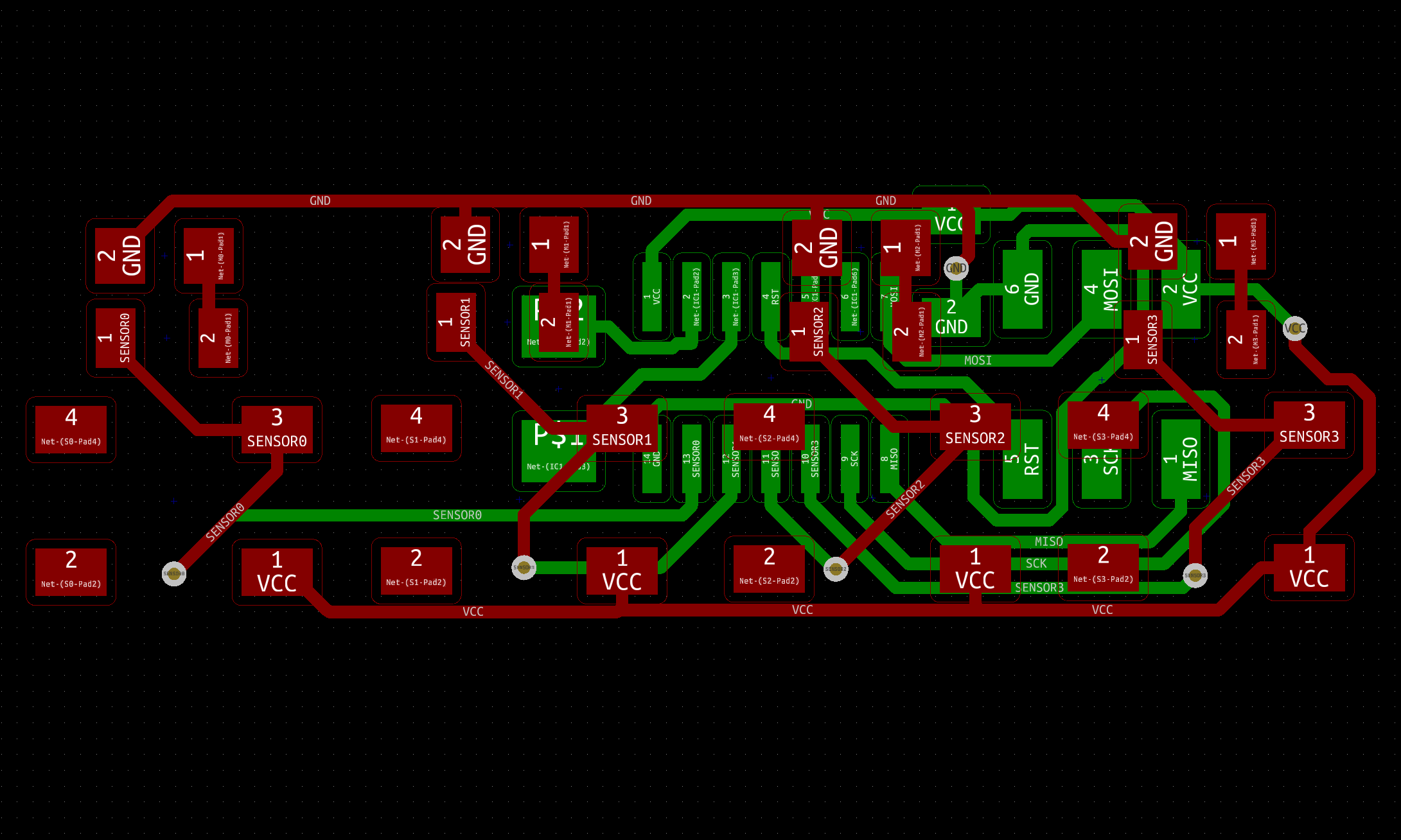
Slave Board
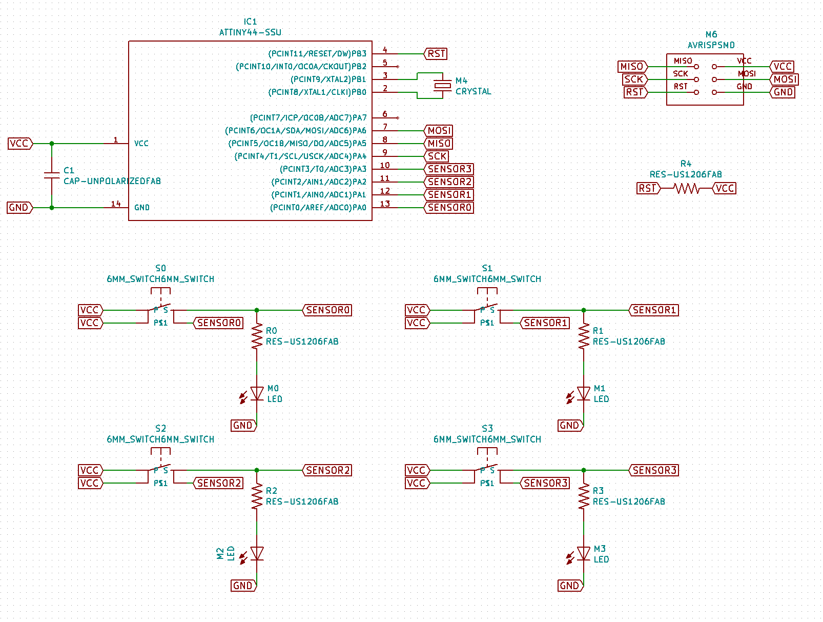
This board will be replicated multiple times to be used in each fret of the ukulele. It has the function to sense where someone is playing or to show where it has to play. Then, this board needs and input and an output, so I decided to use a button to use as an input for the teacher and a LED light as an output. This are the components used:
- Attiny 44
- 4x Buttons
- 4x LED
- 4x 1KΩ for the LED
- 2x3 pin header for the ISP
Crystal 20MHz
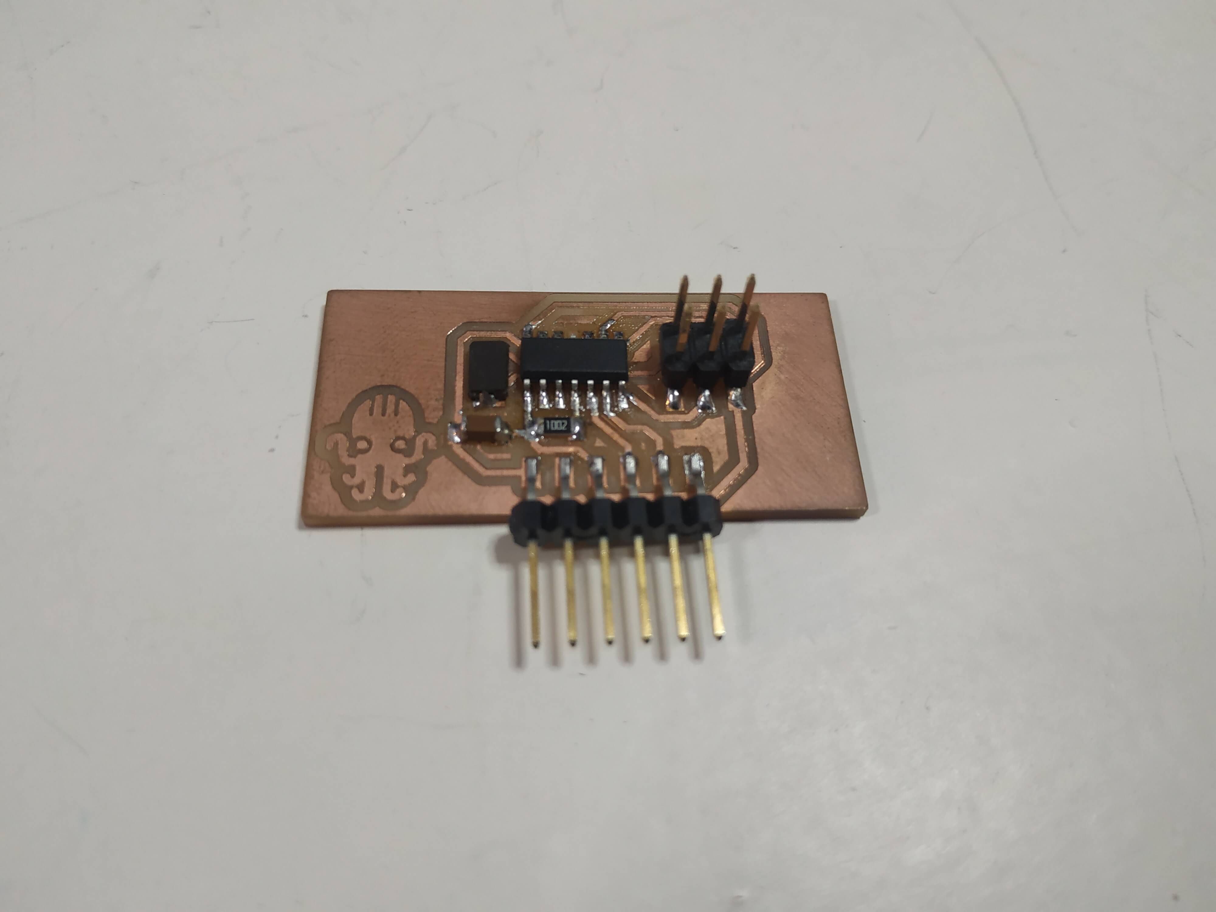
For this board, as I need it to be small to fit in the fret spaces, I decided to mill a 2 side board. It was the first time I did it, so I decided to document it in the Week 06.
Like the master board, it has space for an external clock, but finally I used the internal 8MHz clock of the ATtiny so it is not necessary to solder it. Also, I did a mistake and I didn't connect a pull-up resistor to the Reset pin, but I didn't have any problem with it, it is only necessary for the programing, and I program it correctly.
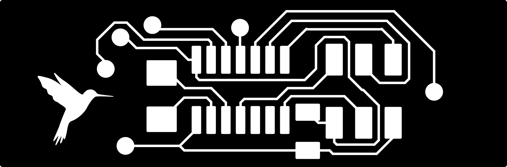
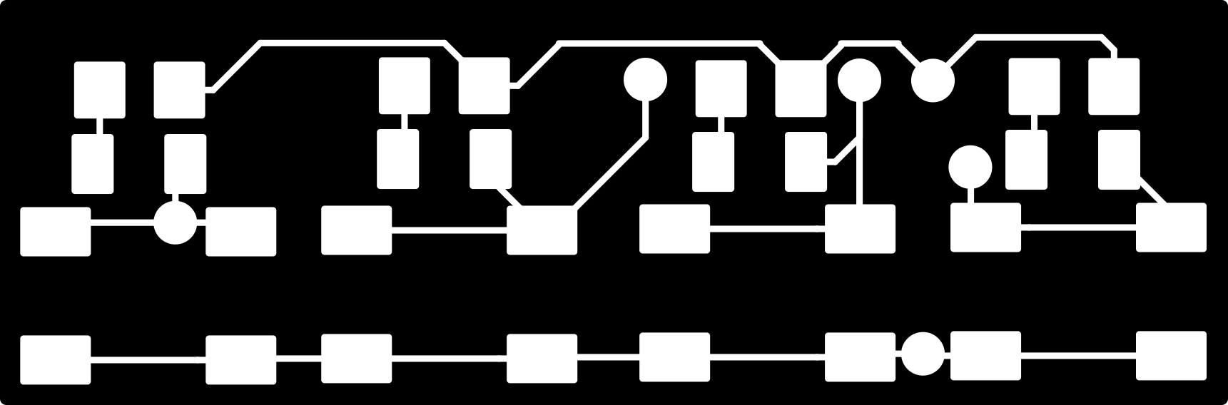
And here is the result from both sides:
Codeing
This was the most difficult part of the assignment. Codeing an I2C communication with an Arduino is really easy using the Wire.h library, but with the ATtinny's is not that simple. I did some research before trying to program my boards, and I found some libraries created specifically for the ATtinny, the TinyWireM for the Master board and the TinyWireS for the slave. Everything seemed to be easy, but after a lot of errors and tests I saw that the TinyWireM was not working fine, at least with the ATtiny 44.
After giving up with the TinyWire libraries, I decided to keep looking for a solution, and after some hours of research and cold sweat, I found the way to make it work! I found another Boards Manager library for Attiny that allows you to use the Wire.h library. You only need to add this link: http://drazzy.com/package_drazzy.com_index.json to the Additional Boards Manager URL's in ArduinoIDE Preferences. Then install ATTiny Core by Spencer Conde from the Boards Manager, and you will see that you have more optipons when selecting your board. Using this profiles you will be able to use the Wire Library.
Slave Code
After having all the setup done, I decided to create a little test script to see if it works ok. I started with the Slave board, the code is really simple:
#include <Wire.h>

byte pins = 0b00000000;

void setup() {
  Wire.begin(1);                // join i2c bus with address #5
  Wire.onReceive(receiveEvent);
  Wire.onRequest(requestEvent); // register event
}

void loop() {
}

void receiveEvent(int howMany) {
  DDRA = DDRA | B00001111;
  pins=Wire.read();
  PORTA = ((PORTA>>4)<<4)|pins;
}

void requestEvent() {
  PORTA = ((PORTA>>4)<<4);
  DDRA &= ~B00001111;
  Wire.write(PINA & (B00001111));
}
What it does is simple, it starts the communication having the address 1 setting the Wire.begin(1). Then I created 2 functions, one for sending the actual state (requestEvent) and one for reading the state (receiveEvent).
- reciveEvent(): First, I set the 4 pins as outputs, then I read the value that it has to be, knowing that this value will be a number between 0 and 15, and reading it as a byte this will be the state of the first 4 bits. Finally, I change the last 4 bits of the PORTA actual state for the lecture, because I don't want to change the state of the other 4 bits.
- requestEvent(): This is the inverse method, I set the pins as Inputs and send the value of this pins setting the other four as 0 to avoid errors.
Master Code
To test that it was working fine I decided to create a simple script that reads the state from device number one and send it to device number 2. This is the script:
#include <Wire.h>

byte state;

void setup() {
  Wire.begin();        // join i2c bus (address optional for master)
}

void loop() {
  Wire.requestFrom(1,1);
  while (Wire.available()){
    state = Wire.read();
  }
  Wire.beginTransmission(2); // transmit to device #1
  Wire.write(state);              // sends one byte
  Wire.endTransmission();
}
As you can see it is really easy, the only thing I would like to comment is the fact that it is really important to end the communication between boards to avoid future problems.
Here it is a video showing how it worked:
Master Code for final project
During Week 15 I created an Interface to communicate with the Ukulele. Everything is explained in that week documentation, but here I will post the Master Code I used for the boards, the Slave has the same code that I just explained. In this code I was using the SoftwareSerial library and the Wire, this was a problem, because it was really heavy, that's by I had to change the ATtiny 44 for an 84 with more memory. This was the only problem I had.
#include
SoftwareSerial mySerial(8, 7);

#include

String mode = "";
int Dev[] = {1, 2, 3, 4, 5};
int nDev = 5; //Change this number accordingly to the number of devices
int State[] = {0, 0, 0, 0, 0};
int PrevState[] = {0, 0, 0, 0, 0};

void setup() {
  Wire.begin();        // join i2c bus (address optional for master)
  mySerial.begin(9600);  // start serial for output
  delay(5000);
}

void loop() {
  //mySerial.println("waiting");
  while (mySerial.available() == 0) {}
  if (mySerial.available() > 0) {
    mode = mySerial.readStringUntil('\n');
  }
  if (mode == "r") {
    readU();
  }
  if (mode == "w") {
    writeU();
  }
}

void readU() {
  for (byte i=0; i < nDev; i++) {
    Wire.requestFrom(Dev[i],1);
    while (Wire.available()){
      byte state = Wire.read();
      byte message = Dev[i] << 4;
      message = message | state;
      mySerial.write(message);
    }
  }
}

void writeU() {
  while (mySerial.available() == 0) {}
  for (byte i=0; i < nDev; i++) {
    byte m = mySerial.parseInt();
    Wire.beginTransmission(Dev[i]); // transmit to device #1
    Wire.write(m);              // sends one byte
    Wire.endTransmission();
  }
}
What this code does is:
- Wait until it receives an 'r' for reading or a 'w' for writing.
- If an 'r' is received, it try to connect with the slave board and ask for it state to store it in the States Array.
- If an 'w' is received, then it waits to receive the desired state and send it to each fret with the function Wire.write().
For this code, I made a special codification to optimize the way it worked. The main goal was to send the less amount of data possible, so taking in account that I need to send 4 bits for each fret being the state of the 4 LED's, I decided to send a byte for each fret, where the first 4 bits will be the device address and the last 4 the state, for example, if device number 1 is totally lighted up, the message will be 0001 1111.
Bluetooth
For the final project I also need to communicate 2 Ukuleles, so I decided to create a BlueTooth serial communication between them. To do it I decided to use the bluetooth module HC-05 because I had some experience with it and one spare module to use. The communication was easy, I just needed to connect it to the serial ports RX and TX to send the data, but first I had to configure the modules. To do it, I followed this tutorial. The main AT commands are:
- AT+RMAAD: Clear any paired devices
- AT+ROLE=0: To set it as slave
- AT+ROLE=1: To set it as master
- AT+ADDR: To know the Address of the slave as it will be used by the Master
- AT+BIND=xxxx,xx,xxxxxx: Where xxxx are the Address of the Slave device to pair it.
- AT+UART=9600,0,0: To set the Baud Rate to 9600
To enter AT mode you have to press the button if there is when you plug your module or set high the Key pin. When the LED start blinking twice twice every 2 seconds they are connected. See the video showing how it worked:
Group Assignment
For this week group assignment we decided to connect our HelloBoards with an I2C Bus adapting my scripts. This was an easy and simple way to communicate our boards, we first wanted to use Bluetooth, but we didn't had enough modules or we only had BLE modules and we had some troubles with them.
The main objective was to control my Hello Board that has an RGB LED using two hello boards to change the color of the LED. To establish the I2C communication we followed what I just explained up, installing th ATTiny Core by Spencer Conde and using the Wire.h library. Those are the codes that we used as a master:
#include <Wire.h>

int State[] = {0, 0, 0};

int but=8;
int R=7;
int G=2;
int B=3;

int Gustavo = 1;
int Diar = 2;

void setup() {
  Wire.begin();
  delay(5000);
}

void loop() {
  if (digitalRead(but)== HIGH) {
    analogWrite(R,255);
    analogWrite(G,0);
    analogWrite(B,255);
    State[0] = 1;
  }

  else {
    analogWrite(R,255);
    analogWrite(G,255);
    analogWrite(B,0);
    State[0] = 0;
  }
  readU();
  writeU();
  delay(10);
}

void readU() {
  Wire.requestFrom(Gustavo, 1);
  State[1] = Wire.read();
  Wire.requestFrom(Diar, 1);
  State[2] = Wire.read();
}

void writeU() {
  Wire.beginTransmission(Gustavo);
  Wire.write(State[2]);
  Wire.endTransmission();
  Wire.beginTransmission(Diar);
  Wire.write(State[0]);
  Wire.endTransmission();
}
And here is the slave's code:
#include <Wire.h>

int LED = 1;  //Change it for your LED pin
int But = 2;  //Change it for your Button pin

int Gustavo = 1;
int Diar = 2;
int LEDState = 0;
int ButState = 0;

void setup() {
  Wire.begin(Diar); //Change the name
  Wire.onReceive(receiveEvent);
  Wire.onRequest(requestEvent);
}

void loop() {
  if (digitalRead(But)==HIGH) {
    ButState = 1;
  }
  else{
    ButState = 0;
  }
  if (LEDState == 1) {
    digitalWrite(LED, HIGH);
  }
  else {
    digitalWrite(LED, LOW);
  }

}

void receiveEvent() {
  LEDState=Wire.read();
}

void requestEvent() {
  Wire.write(ButState);
}
This is a video showing how it worked: