8 - Embedded Programming
Program my board
For this week we need to program our board, so I get my board from Electronics Design week and program it! As I was really busy this week finishing my CNC assignment I will document the programing I did in week 6 and the different ways I tried to program it.
Reading the datasheet
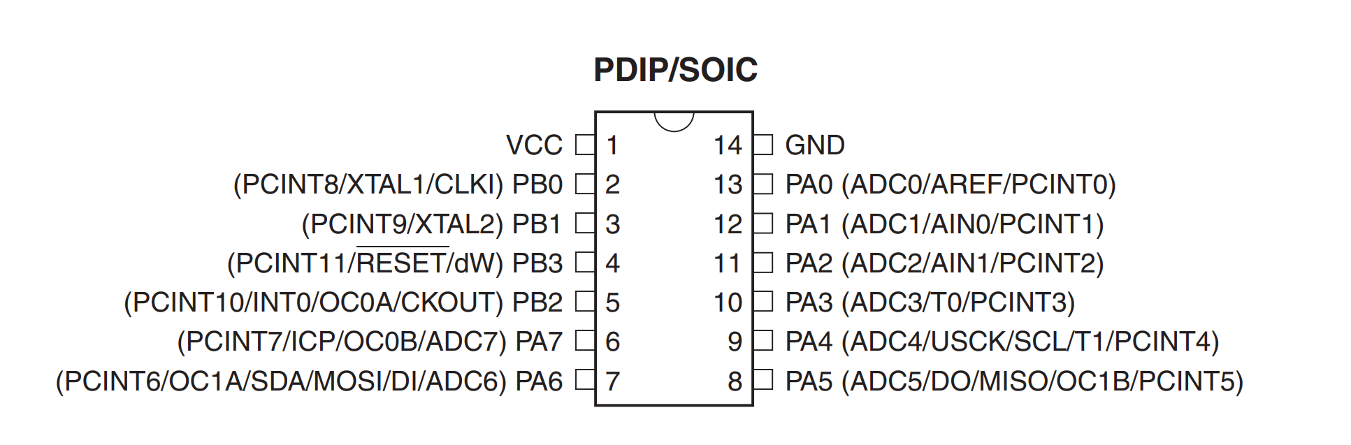
My board uses the Attiny 44 micrcontroller, so, befor start programming it, it is important to read it's datasheet to know how to do it. It is really interesting because you learn how it works, the different types of pins it has and how you can use them. It also shows some codes to program it and different options of configuration, for example the Reset button and how to disabel it to use it as a normal B pin.
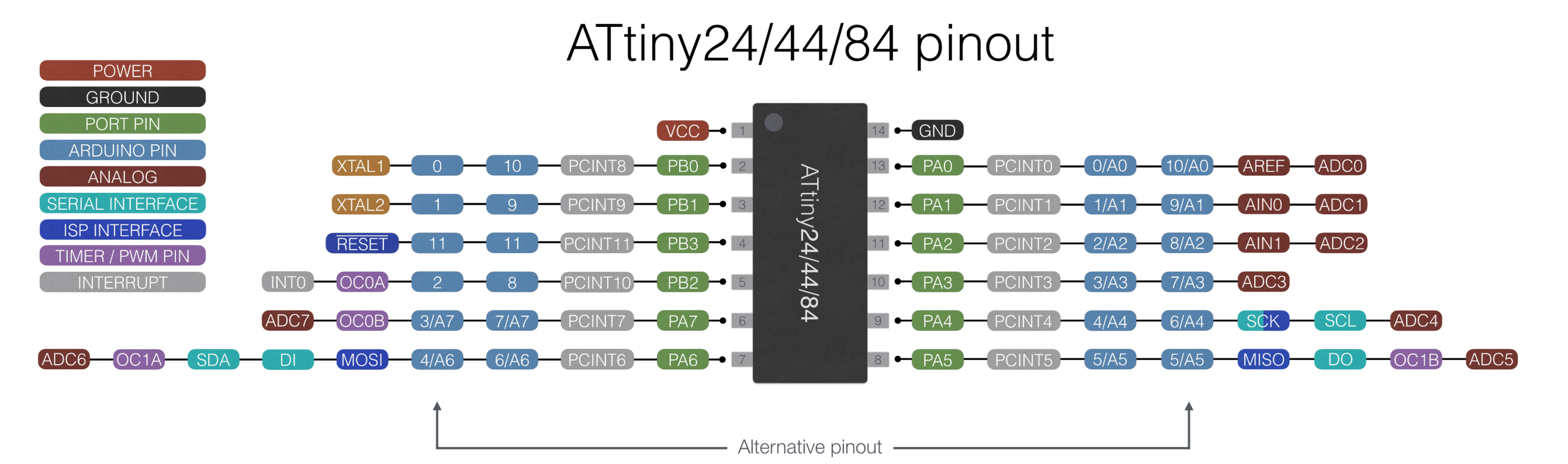
Here it is the Attiny 44 Pinout and the equivalent for different boards:
Using Arduino IDE to program it
I was used to program with Arduino in the past, so beeing able to program my board with it was really helpfull. Arduino is a C base code language easy to learn and use, but also is heavy for the microcontroller, so learning to program in C would be really usefull. But first, let's program something with Arduino!
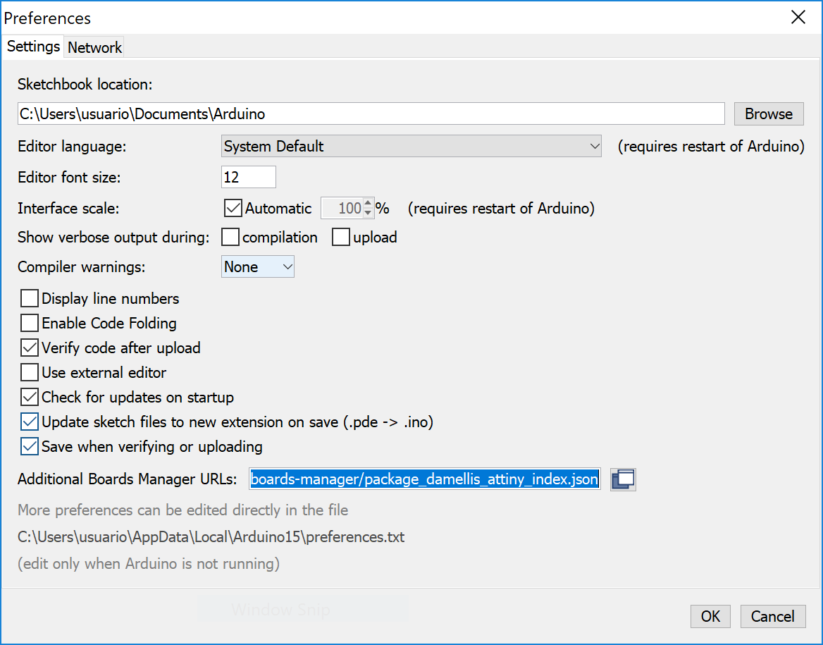
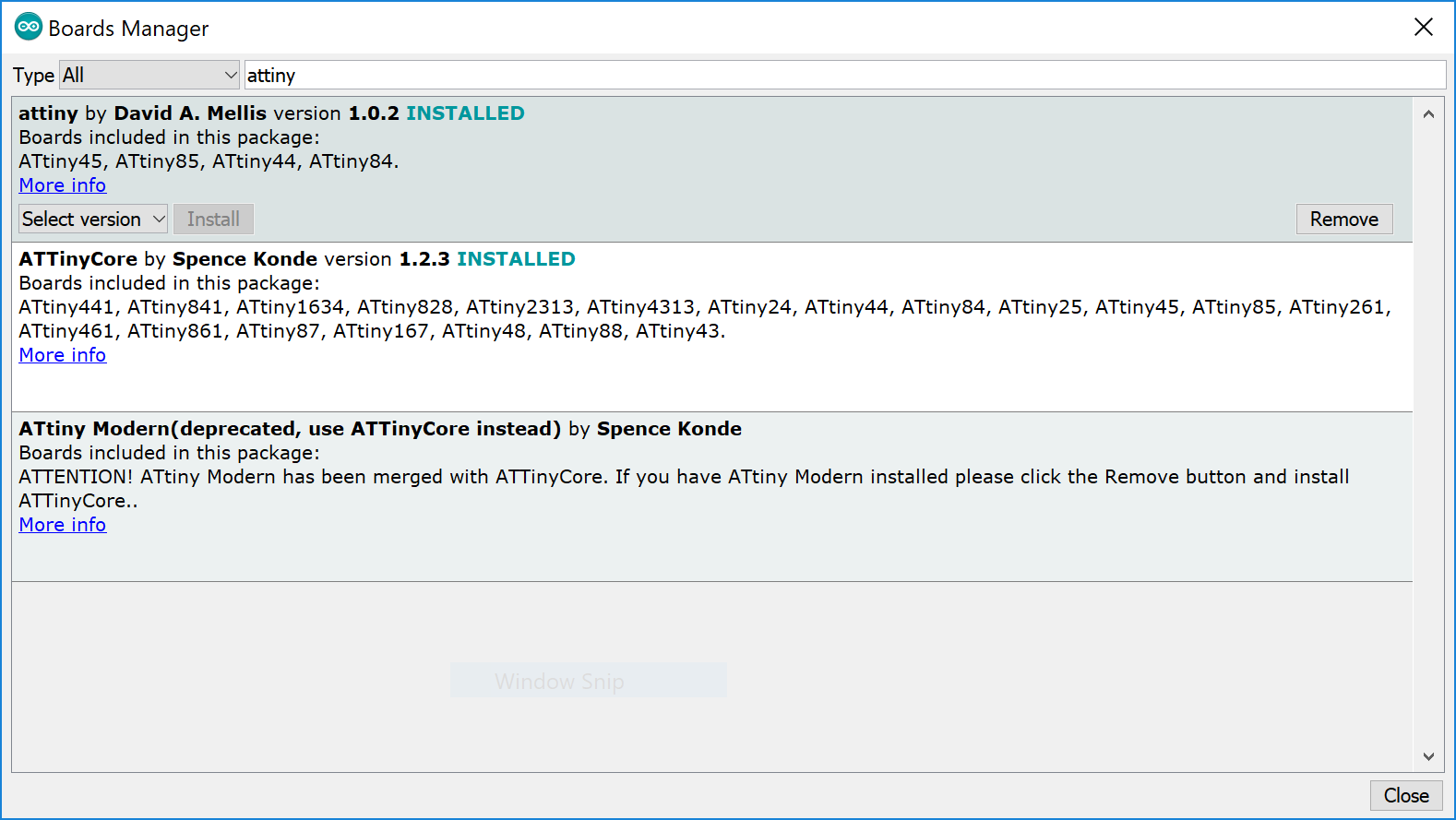
The first step is get the configuration ready to use an Attinty 44 with Arduino. To do it, I had to install the correct boards manager. I just followed this tutorial to get the perfect configuration. I used Arduino 1.8.1 and everything worked, but they allways recommend using Arduino 1.6. This are the important steps of the tutorial:
- Add a new board manager URL: Select File/Preferences/Additional Boards Manager's URL and paste this URL https://raw.githubusercontent.com/damellis/attiny/ide-1.6.x-boards-manager/package_damellis_attiny_index.json.
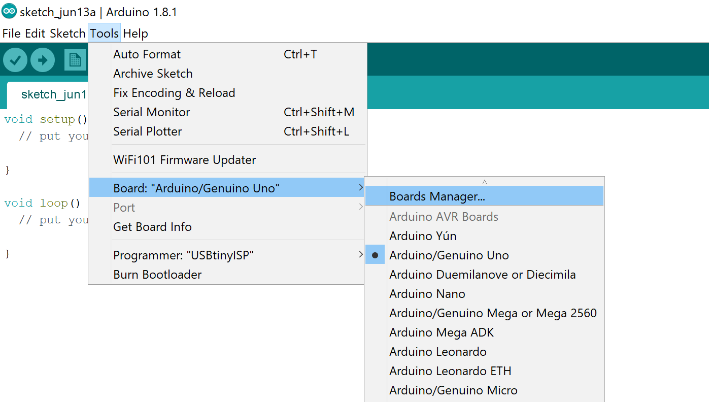
- Install the ATtiny library from Tools/Board/Boards Manager, seach ATtiny and install the attiny by David A. Mellis.
- Restart the IDE.
Programing the Hello Board
During Week 6 I designed a Hello Board with an RGB LED and I program it to show it's capabilities. I program it using the Arduino IDE and here I will explai how it works a little bit.
The first step is to know how this program works. It is divided in 3 main parts, the initialization part where you can import libraries and define global variables, the void setup () where the setup of the board is done and the void loop () the loop that will execute when it is powered.
Let me explain how it works with my code, it starts like this:
#include <SoftwareSerial.h>
SoftwareSerial mySerial(8, 7);

int R=7;
int G=2;
int B=3;
int but=8;
int ButtonState=0;
int PushCounter=0;
int lastButtonState=0;
First I imported the SoftwareSerial library to connect the board with the computer throught the serial port. (This is not used in this code, but it is interesting to know). Arduino boards have specific pins for Serial communication and they have it's own library Serial.h, but ATtiny chips didn't have this connection , so we simulate it with two other pins, in this case 8 for RX and 7 for TX to communicate with the pc. I named my connection as mySerial.
Then, I defined a series of global variables, all with of them are integers int to define the diferent pins of the RGB LED. Also I defined the state of the Button, the previous state and a counter.
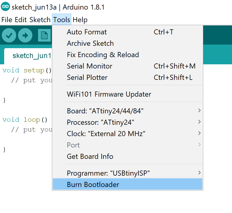
The next part is the void setup(). This function is the first one called by the program and it runs one time when the board is powered. Here are defined the settings of the board, the things that will not change during the running time to set them first and then pass to the loop.
void setup() {
  pinMode(R,OUTPUT);
  pinMode(G,OUTPUT);
  pinMode(B,OUTPUT);
  pinMode(but,INPUT);
}
What I did in this case was to set the pins as Inputs (the button) and Outputs (the 3 pins of the LED). This definition is made here because this state will never change so, if we define it in the program loop this will be set up like this each time. Setting it here allows us to set it for one time and forget about it anymore.
Finally there is the void loop() function. This function is executed in a loop, one time after the other until the board gets disconnected. Here is where the code of the program has to be programmed, here you can check the status of the inputs and change the inputs, for example.
void loop() {
  if (digitalRead(but)== HIGH) {
    analogWrite(R,255);
    analogWrite(G,0);
    analogWrite(B,255);

  } else {
    analogWrite(R,0);
    analogWrite(G,255);
    analogWrite(B,255);

  }
  delay(50);
}
This part is simple, I only check the status of the button, if it is HIGH the Green LED it's light up and the other two turned off, but if the button is LOW the color will be Red. Here is a video showing the result.
C Code
I decided to try to learn some C code to make smaller programs and get out more of my boards, so I get a copy of the book Make: AVR Programming by Elliot Williams and start reading about it.
I find it very very interesting but I didn't have enought time to lear a lot of it. I didn't program my board with C Code, but I learned some nice tricks that I used afterwords in the next weeks. For example I used some bit shiffting technics and Port definitions in Week 13 for example.
This are some notes I get from the lecture:
- Ports divided in groups of 8 (8bit for one byte).
- DDRx (x is the group of pins) defines the pins as inputs or outputs: 0b00000001 (1 is output, then pin PB0 is output).
- PORTx defines Outputs as High or Low and Inputs as Pull-Up Resistor or Disconnected (Hi-Z).
- PINx reads the value of the Inputs. Cannot be write.
- Bit Shiffting: Move the bits with << or >>:
- 0b00001110 >> 3 = 0b00000001 move 3 positions to the right (add 0 to the left)
- 0b00001110 << 2 = 0b00111000 move 2 positions to the left (add 0 to the right)
- Example: (1<<0) = 0b00000001 (1<<3) = 0b00001000 (1<<7) = 0b10000000
-
Bit Operators:
- | OR: 1010 | 1100 = 1110 (If there is a 1 then 1)
- ^ XOR: 1010 ^ 1100 = 0110 (1 if only one is 1)
- & AND: 1010 & 1100 = 1000 (1 if the tow of them are 1)
- ~ NOT: ~ 1100 = 0011 (Change all values)
- Are common operations, they have shortcuts: PORTB = PORTB | (1 << 2) can be write as PORTB |= (1 << 2)
- Set a pin ON with OR:
- PORTB = 0b00001000
- PORTB |= (1 << 1) = 0b00001010
- PORTB |= ((1 << 0) | (1 << 2)) = 0b00001101
- Toggle a pin with XOR:
- PORTB = 0b01101001
- PORTB ^= (1 << 3) = 0b01100001
- PORTB ^= ((1 << 4) | (1 << 5)) = 0b01011001
- Clear a pin with AND and NOT:
- PORTB = 0b11000011
- PORTB &= ~(1 << 1) = 0n11000001 ~(1 << 1) = 0b11111101
- It is possible to program macros instead of using that syntax:
- #define BV(bit) (1 << bit)
- #define setBit(byte, bit) (byte |= BV(bit))
- #define clearBit(byte, bit) (byte &= ~BV(bit))
- #define toggleBit(byte, bit) (byte ^= BV(bit))
- Loops:
- while(condition) --> while(i < 10)
- for (initial state; condition; value change) --> for(i = 1; i < 8; i++)
This is an example of the code I used, where I apllied this technics to make a lighter code and easier to compile. Here I change the port definitions and the states of the pins in a single line for example.
#include <Wire.h>

byte pins = 0b00000000;

void setup() {
  //DDRA = DDRA | B00001111;
  Wire.begin(5);                // join i2c bus with address #5
  Wire.onReceive(receiveEvent);
  Wire.onRequest(requestEvent); // register event
}

void loop() {
  //delay(100);
}

void receiveEvent(int howMany) {
  DDRA = DDRA | B00001111;
  pins=Wire.read();
  PORTA = ((PORTA>>4)<<4)|pins;
}

void requestEvent() {
  PORTA = ((PORTA>>4)<<4);
  DDRA &= ~B00001111;
  Wire.write(PINA & (B00001111));
}
Conclusion
This was an interesting week, I get myself started with C programming, I didn't manage to program with it but I get really interested, so I would try to keep working on it and learn this lenguage to make more things possible.