7 - Computer-controlled Machining
Group Assignment
For this week's group assignemtn we needed to test the machine and the feeds and speeds with our material to see wich parameters to use. To do it, we prepared a test file with our instructor and then try it in the machine. This are the steps we followed:
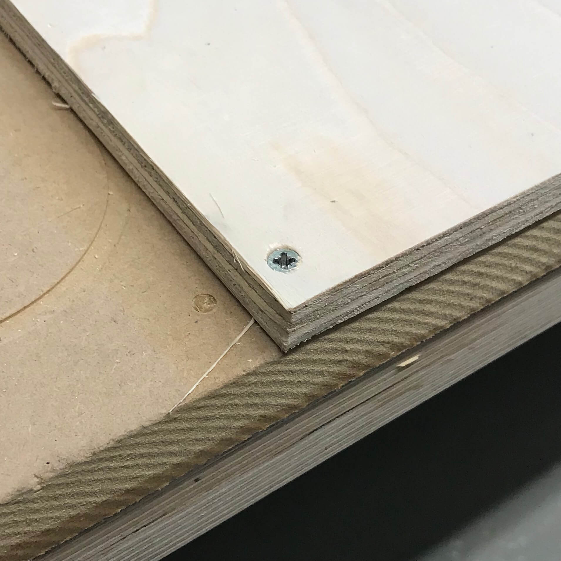
Mesure and fix the material
It is important to measure the full sheet from every corner. It is common to have different thickness through the material, due to fabrication or storage conditions. For instance, if the board is standing on the ground, the bottom corner may absorb humidity and be ticker.
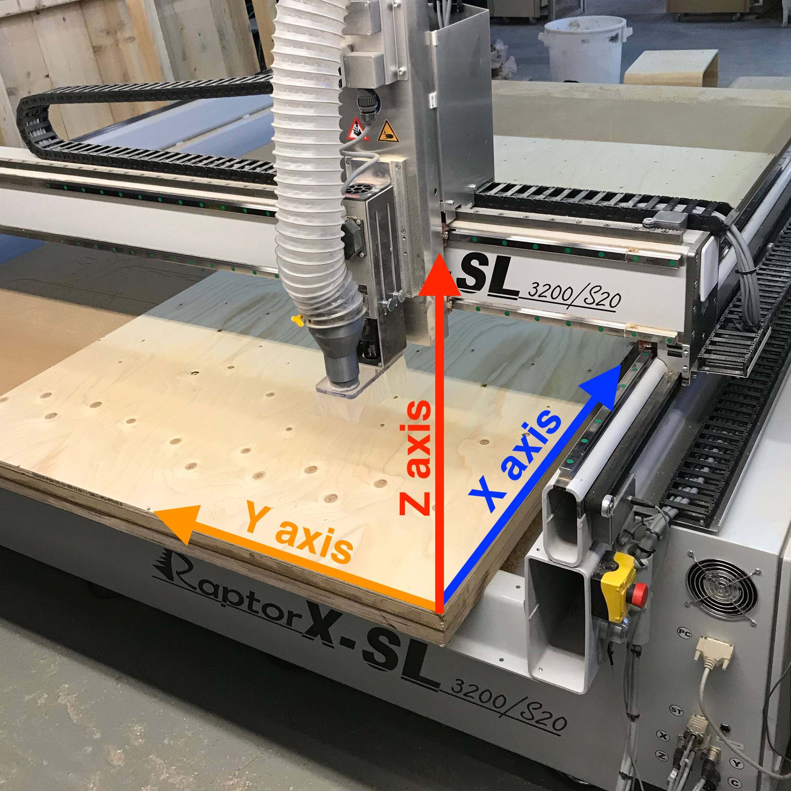
Remember the 0 position of the machine is set by deffault to the bottom left corner and that the X axis is the long side of the machine.


The end mill
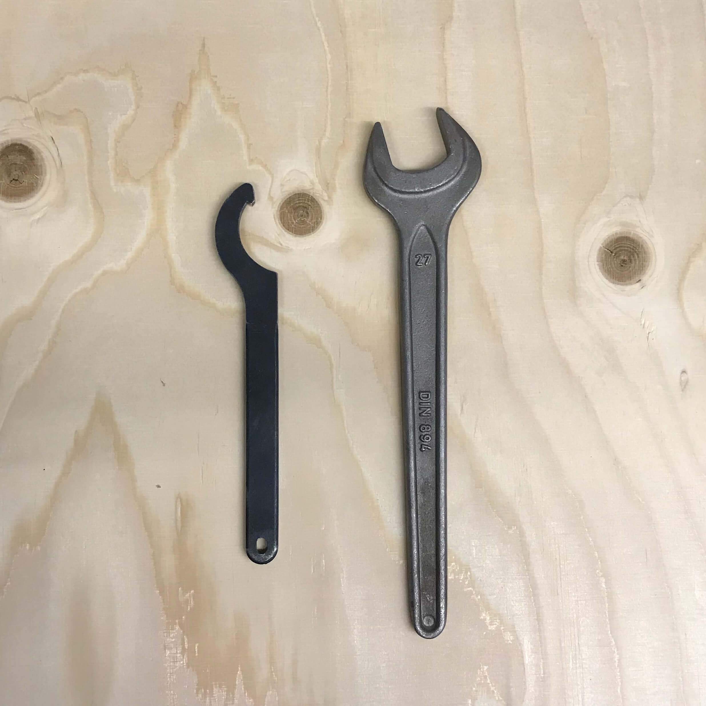
If necessary, you can remove the dust collector to make it easier to change the tool. Use the machine’s wrench and key to release the collet and holder.
For safety, don’t hold it from the flutes. You can easily cut yourself. It is recommended to hold the shank instead.
A little trick to get the collet out of the holder is to press it laterally.
You should leave around 2-3mm of the shank out of the collet and then tighten with the wrench.
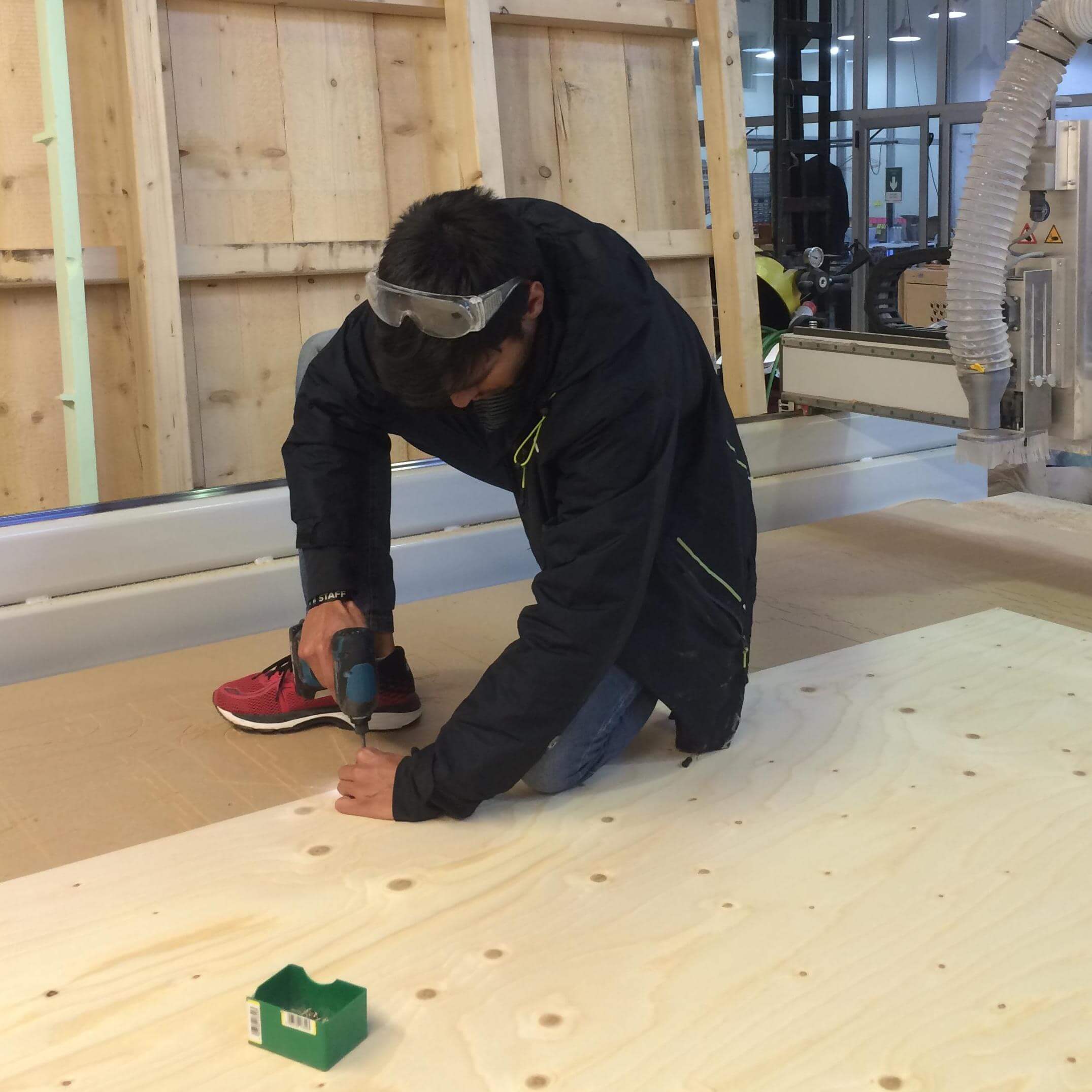
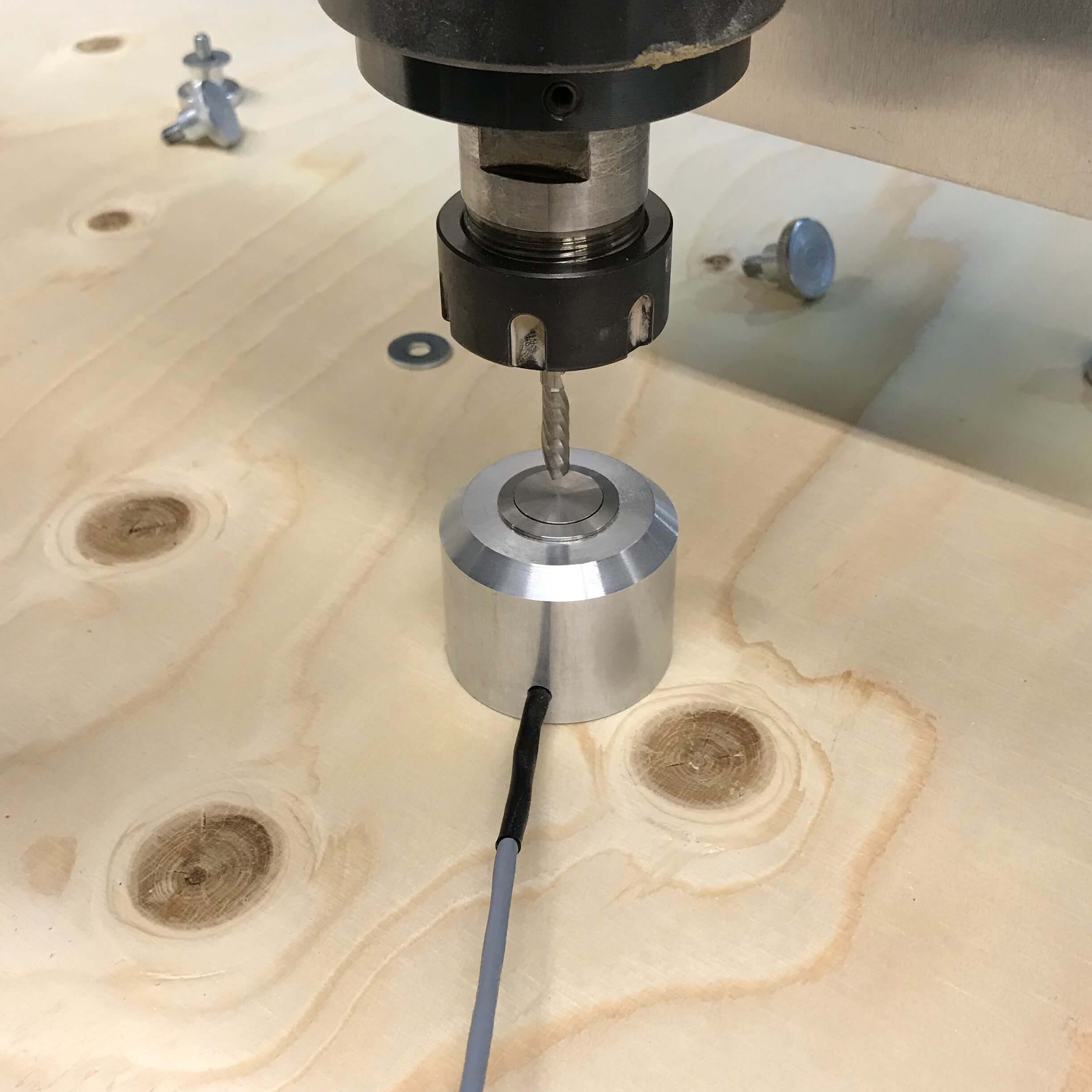
Set each axis origin
If you placed the board aligned with the machine bed, X,Y could be set by sending it to home, if not, move then to the origin of your board and set the 0 there.
To set Z, we have the auto-leveler, that should be set right under the tool.
Start the job
After doing all that, is time to start the machine, but first, a couple of checks:
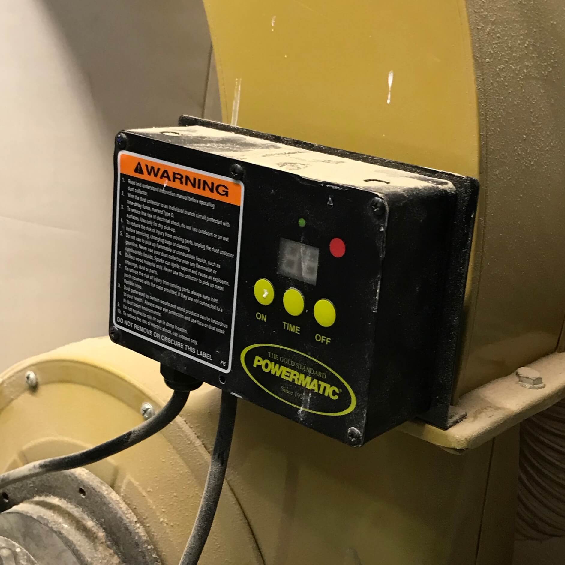
Make sure dust collector is on.
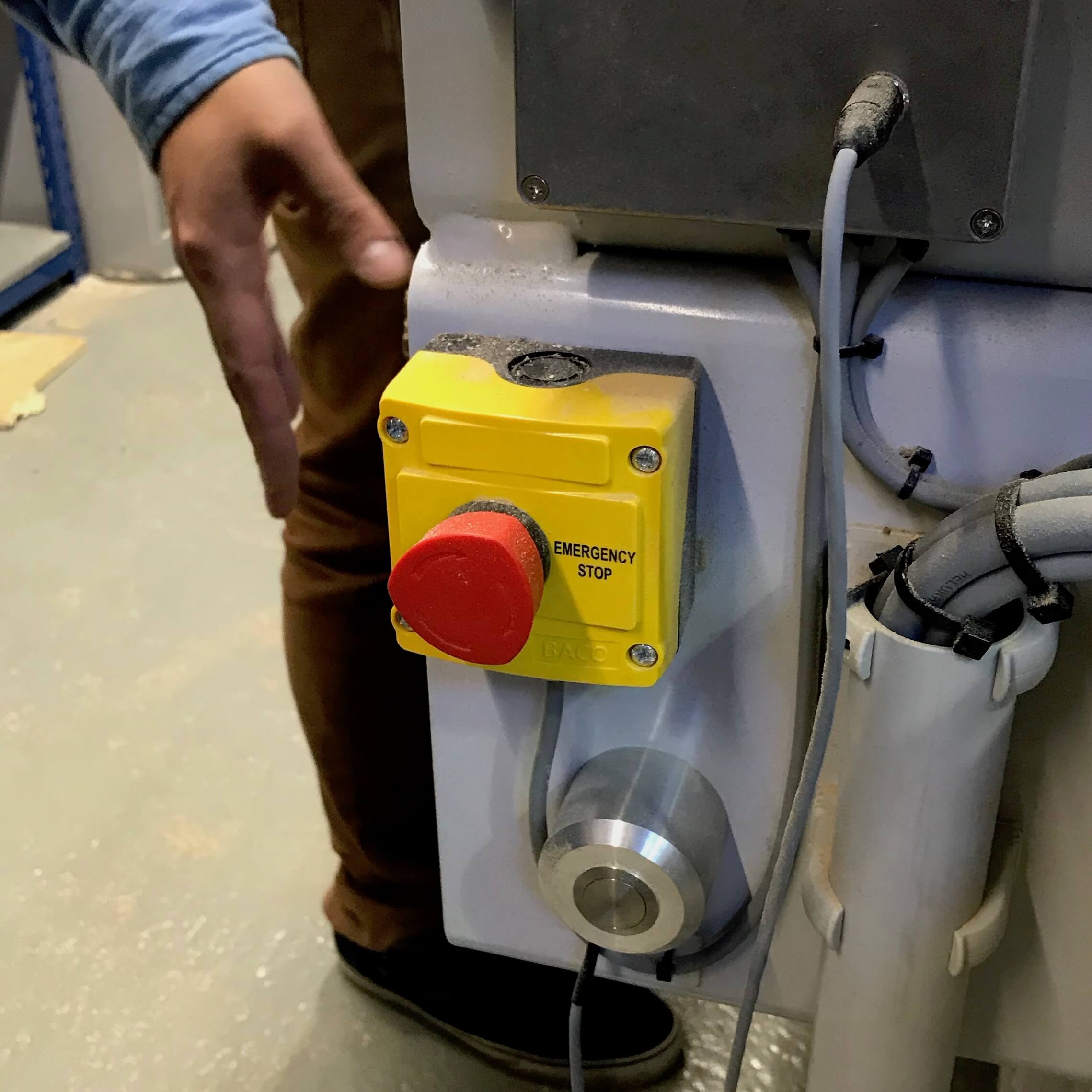
Make sure you know where the emergency button is.
Wear safety glasses, closed shoes and earmuffs. Only then, start the job.
Finish job
After finishing, move the axis away so you can reach the cutout pieces, turn off the machine and dust collector, only then proceed to remove the material. Remembering to clean after yourself and store all the tools and protection gear.
Chip load Calculation
A really basic calculation is to multiply the spindle RPM x number of flutes X chip load, to get the appropriate feed rate.
We got 2440x1220 15mm spruce plywood boards. After a quick search, we found that the chip load is between .011”-.013”. Since our machine is set up in millimeters, we did the following calculations.
- 18k x 1 x 0.28 5040
- 20k x 1 x 0.28 5600
- 22k x 1 x 0.28 6160
- 24k x 1 x 0.28 6720
Tests
Even tough we had the numbers, we wanted to try the possible combinations, varying from 18k RPM with 2k feed rate, up to 24k RPM with 7000 feed rate.
But, the math does not lie. The best results were the ones we previously calculated. This are the results with a downcut end mill.
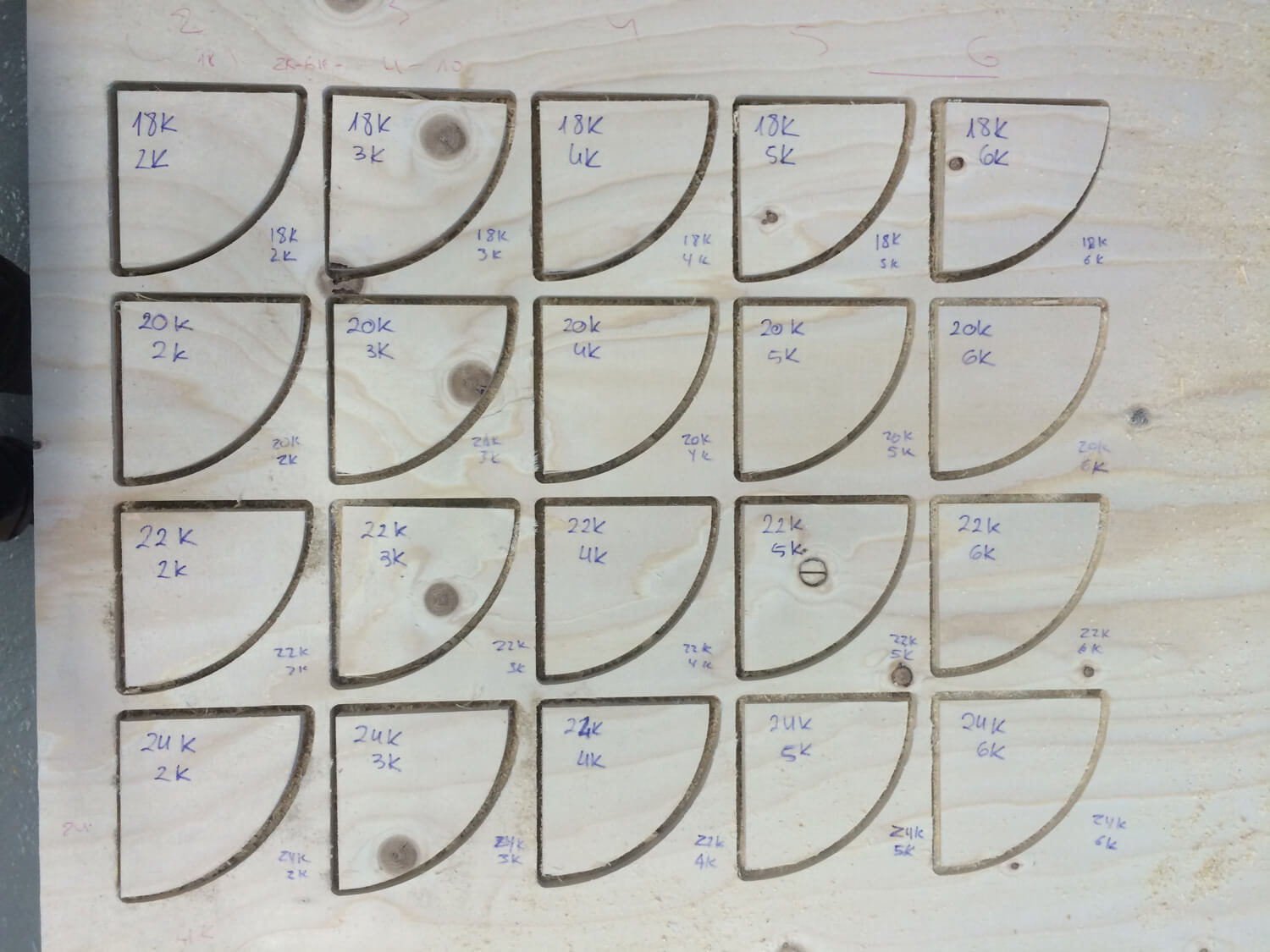
We repeated the test with a up cut as well and got batter results. But probably the main reason is because the tool was newer and more sharp.
Individual Assignment - Tahitian Ukulele
Idea
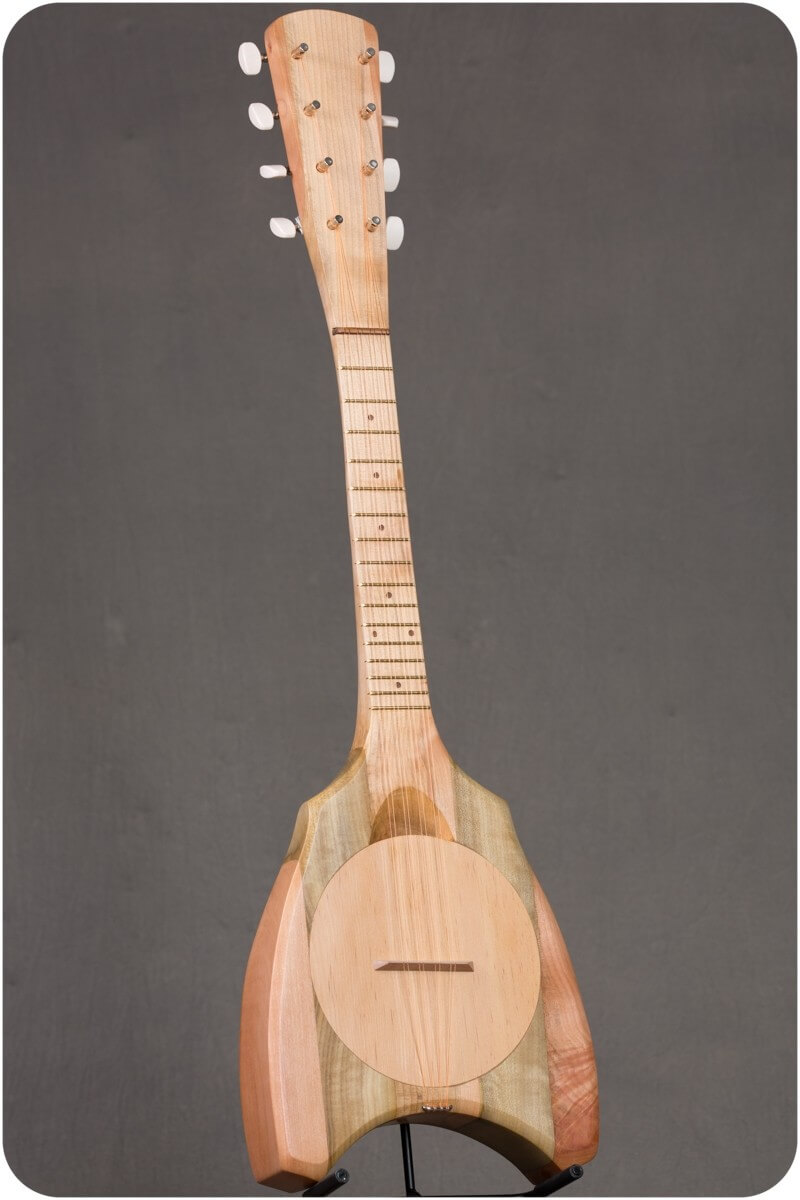
For this assignament we need to do something big, but I din't wanted to do a chair or a simple furniture to just get the assignment done. I wanted to do something especial for me and that could help me with my final project, so I started thinking what should I do. First we did the group assignment in the first 2 days, so I had all the weekend to think in something big. Looking throught the internet fir things related to Ukuleles (as my final project is one Ukulele) I found the perfect item: The Tahitian Ukulele! It is a type of Ukulele produced in the island of Tahiti with a solid wood body with a back hole used to resonate the music inside. It is made of wood, can be cutted in the CNC and it looks amazing! Also it would help me learning how to build an instrument before trying for first time with my final project.
Design
I design it with Fusion 360, I tried to keep a nice shape for the body and giveing it a 380mm freat scale like the concert Ukuleles. To learn about wood joinery I decided to divide the ukulele in 2 parts, the neck and the body, and join them with a hidden join. This is the design:

CAM
With the design finished, I did the CAM with RhinoCam. It is an addon extension of Rhinoceros and we have acces to it in the lab's computers. This week was a busy week because we were a lot of students trying to use the CNC machine, so all the process was slow.
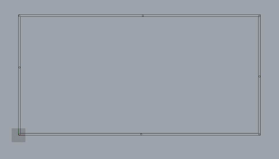
The first thing I did in Rhino was defining the material size and creating a rectangle with the full shape of my board and do some point that will be engraved to position the screws. Then I decided to try different tolerances with some join tests.
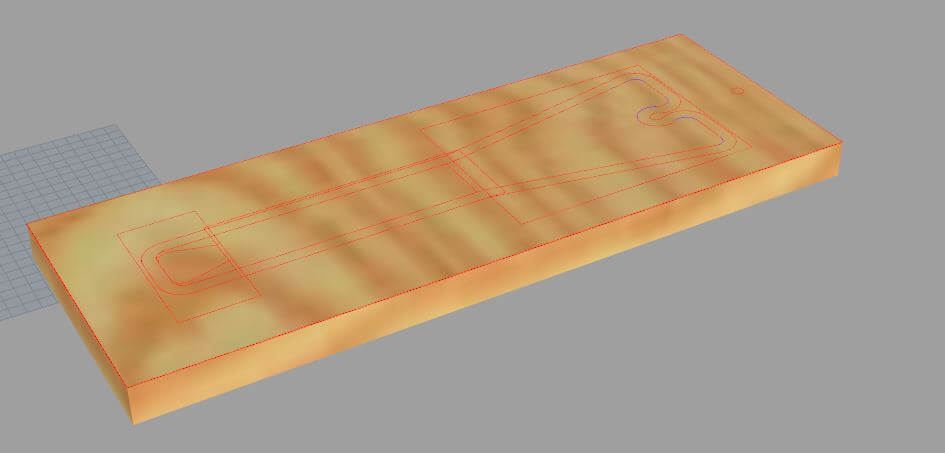
Body
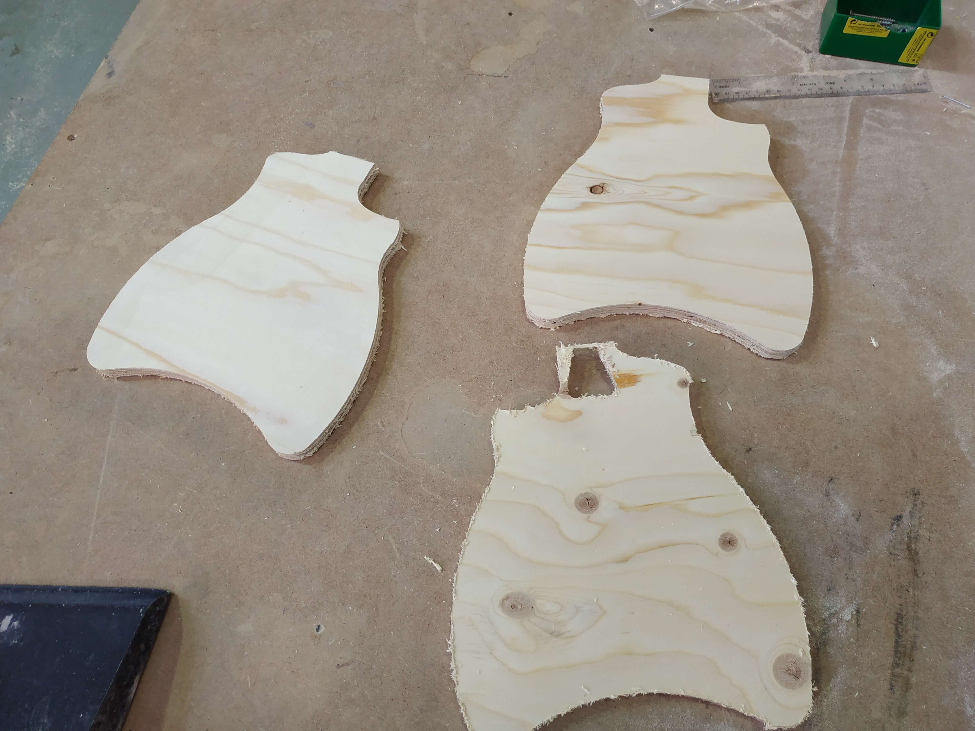
To create the file, I exported the Fusion 360 sketches as DXF and then imported to Rhino. A nice strategy is to change the colors depending on wich type of operation is it for, pocketing, profiling or engraving. I started with the body of the Ukulele. As the thikness of the body needed to be more than 15 mm (the thikness of the material), I decided to use 3 layers, cut them and glue it together. Also I did a pocketing of the hole to know where the center is and then 3D cut the real hole of the whole body.
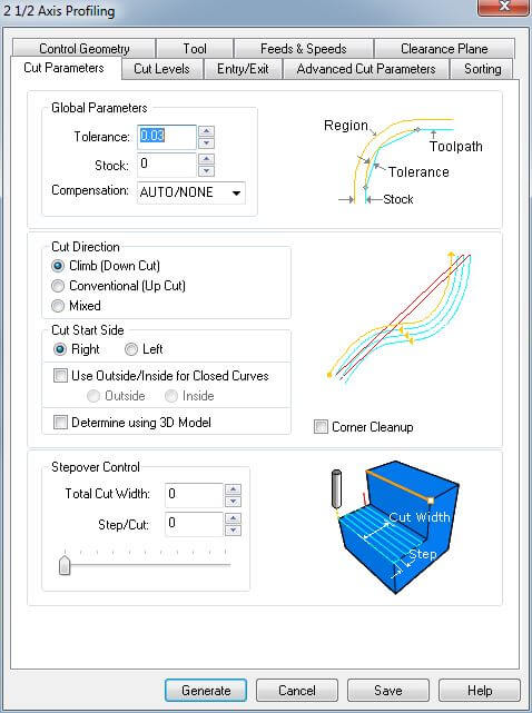
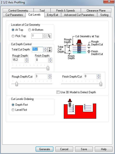
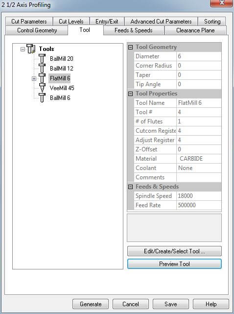
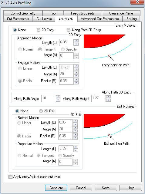
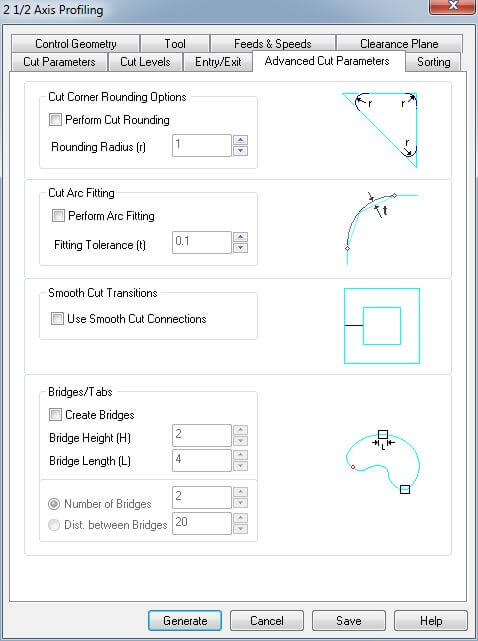
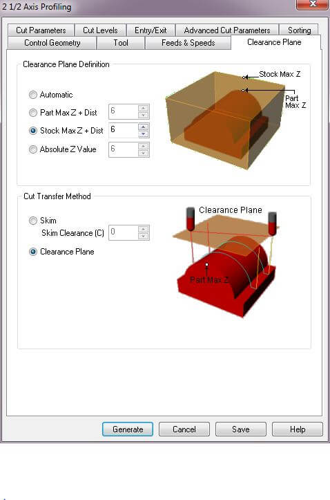
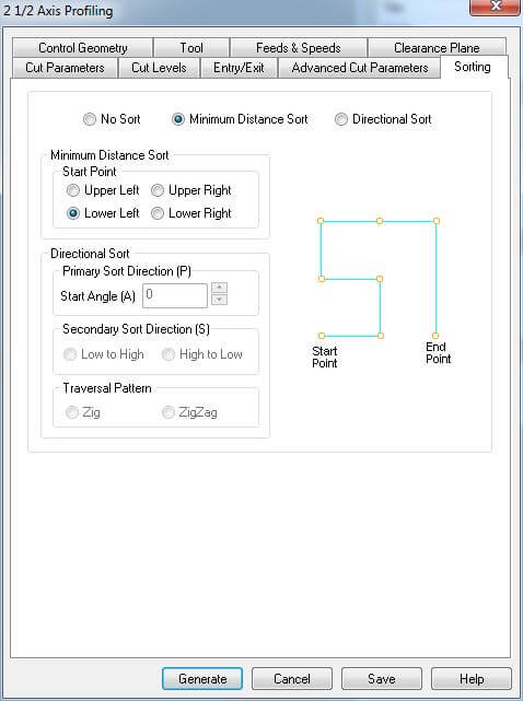
For this operations I used a ∅6 mm Down cut Flat end mill. It was the same used for the group assignment, so I used the feed's and speed's that we found. They where calculated with the Chip Load Calculation Feed Rate = #Flutes · ChipRate · RPM, it was a 1 flute mill and the Chip Rate was between 0.28 and 0.33 as Plywood is considered Softwood. The result was 18000 RPM and 5000 mm/s. This are the parameters used for the pocketings:
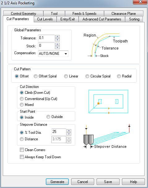
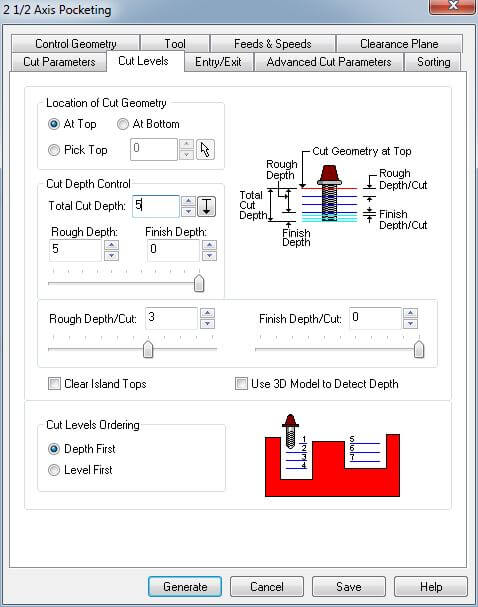
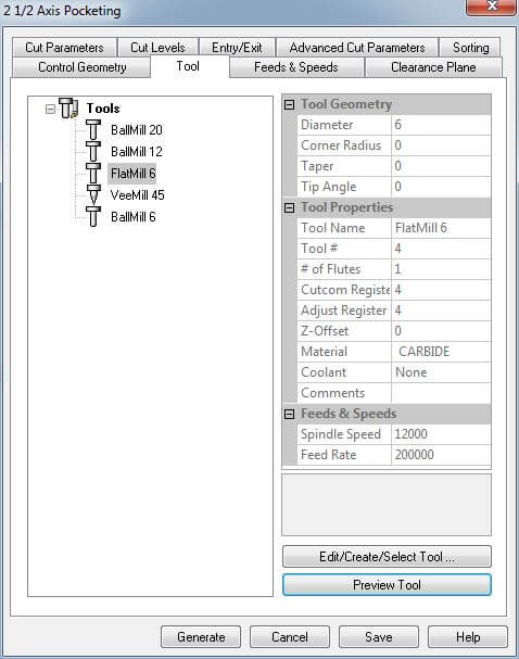
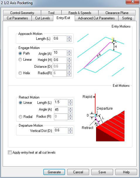
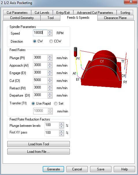
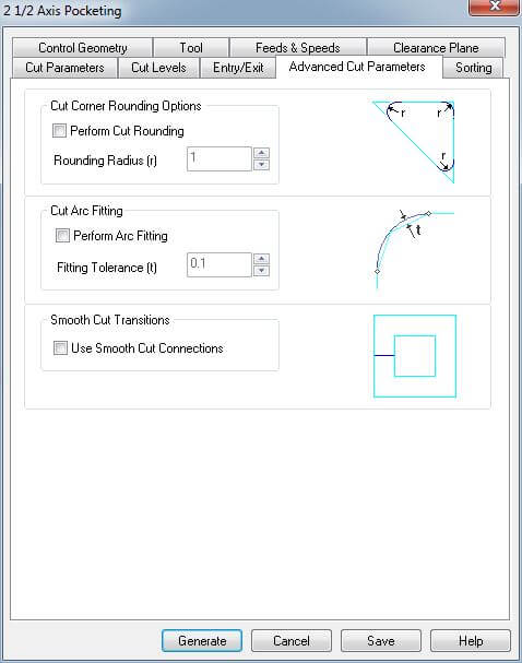
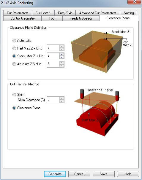
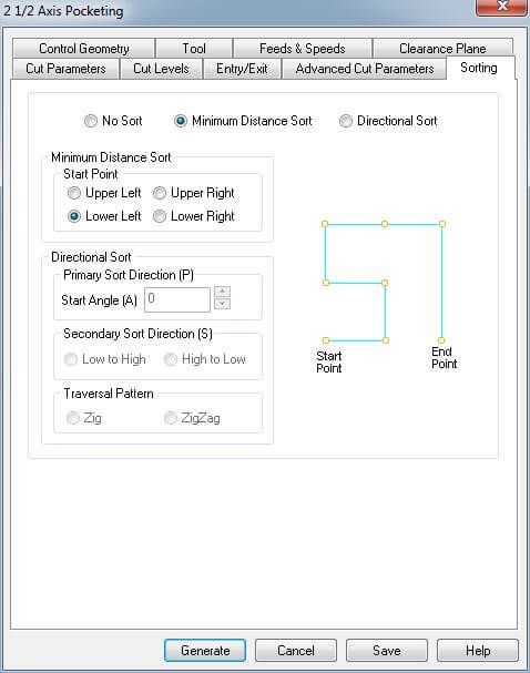
And those the ones used for the profiling:

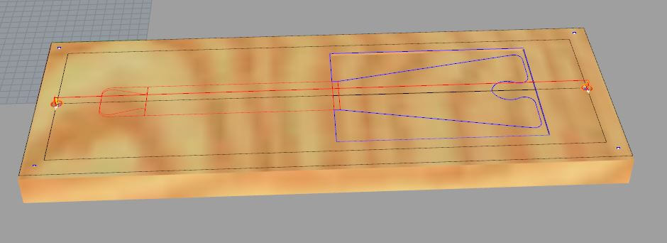
Neck
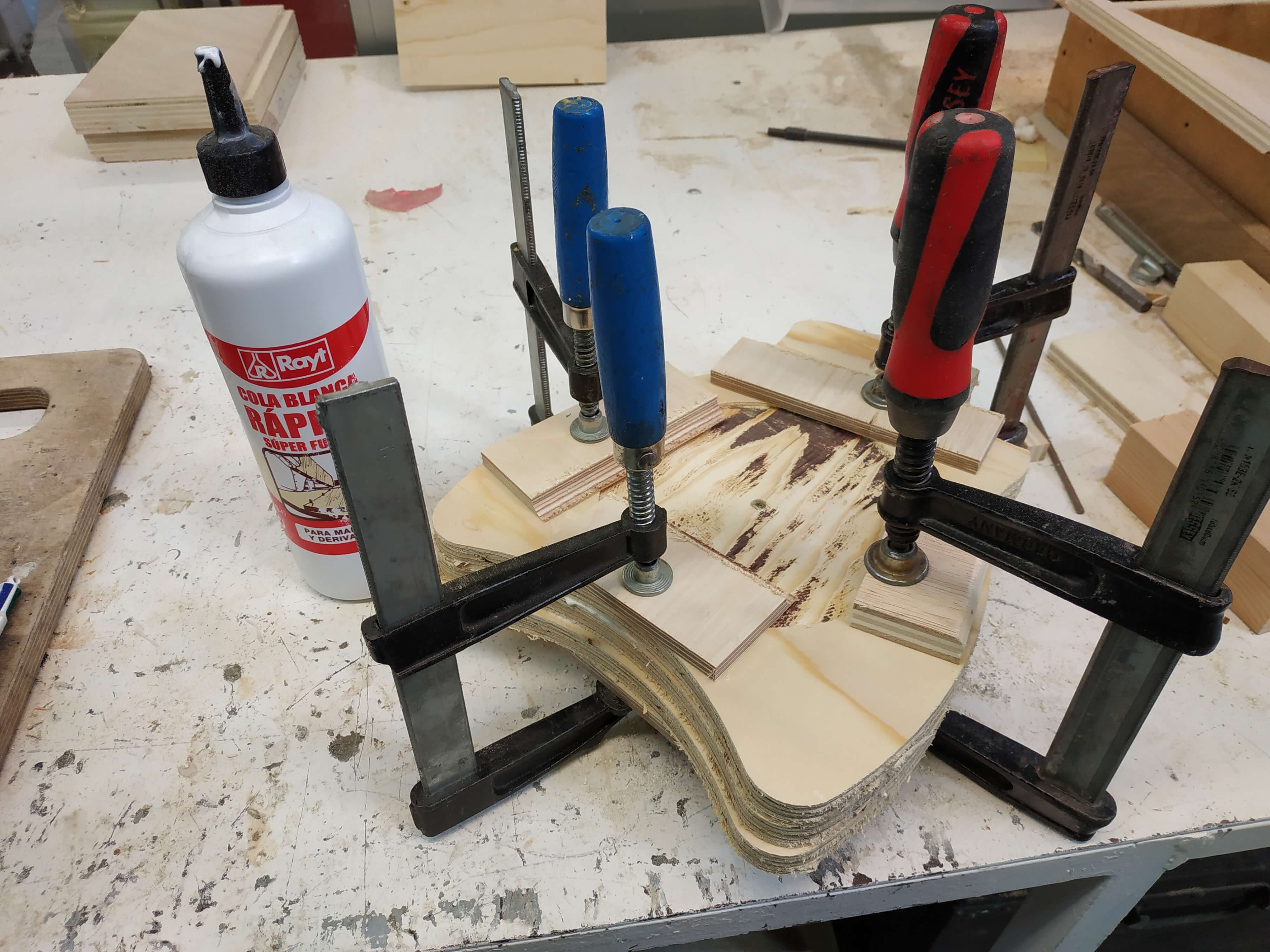
For the neck I tried another technic. As the thikness was more than 15 mm I decided to try to glue two pieces of wood and then cut them together this time. So the first step was glueing the two pieces.
Then I did the CAM file. This was the most difficult part, because it needed a two side milling for the head of the ukulele and a 3D milling process for the round part of the neck. The first side was only a pocketing to make the head lowwer than the fets, and two holes that goes a little bit through the sacrificial board to be able to center the board after flipping it to mill the second side.
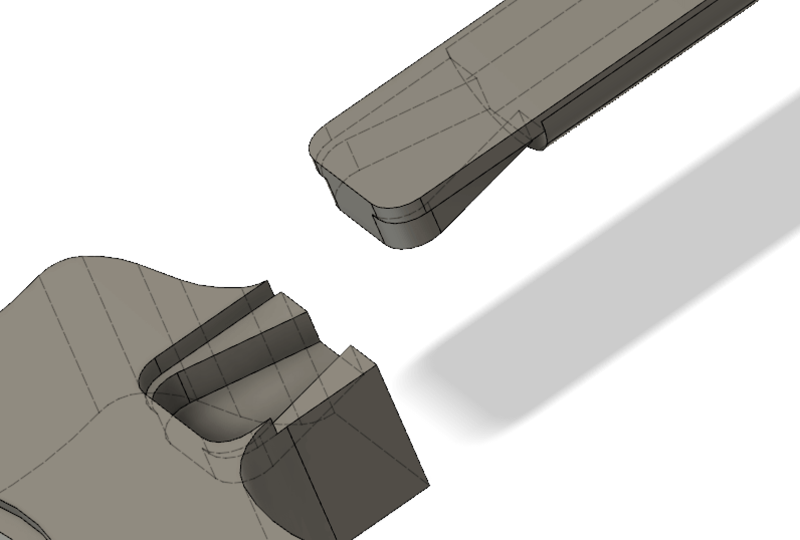
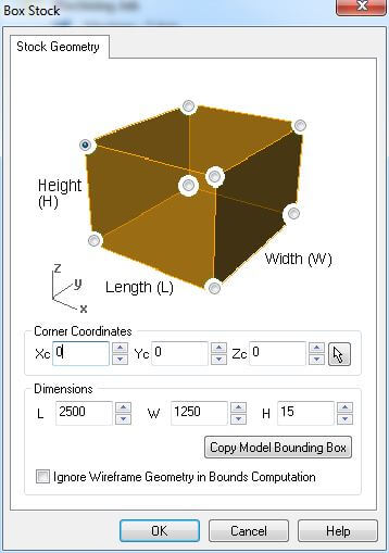
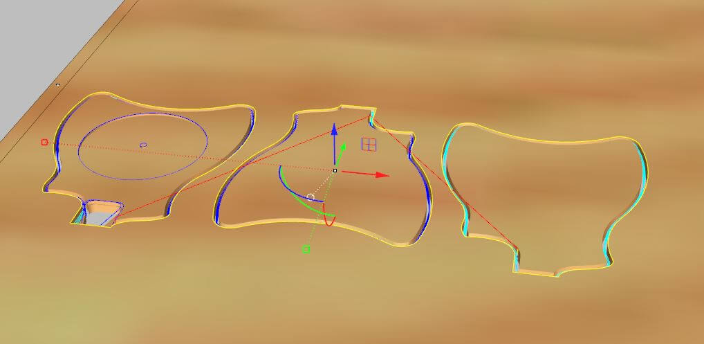
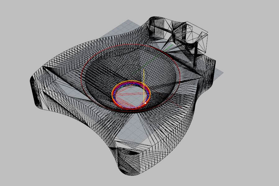
The second side was much more interesting, it has a 3D shape, my first 3D mill. To do it I needed to import the 3D model in Rhino and put it inside the Box Stock shape to create the 3D milling operations. It will automatically detect the mesh and create the tool path.
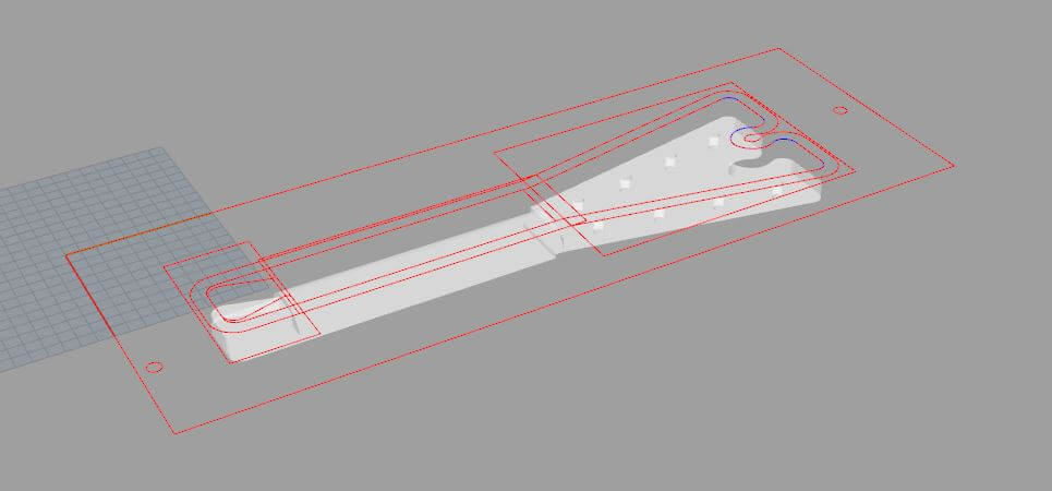
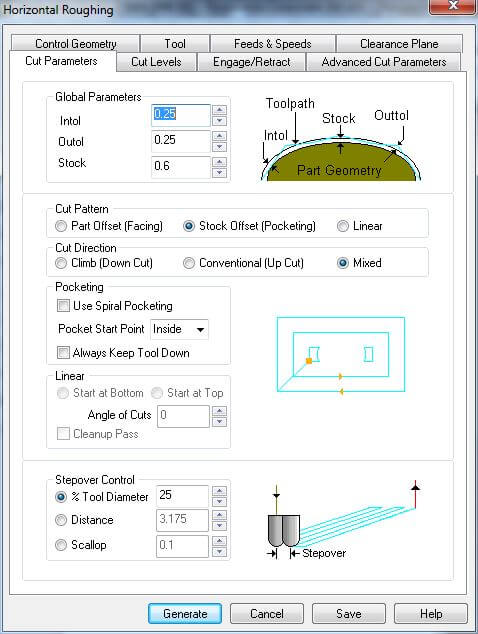
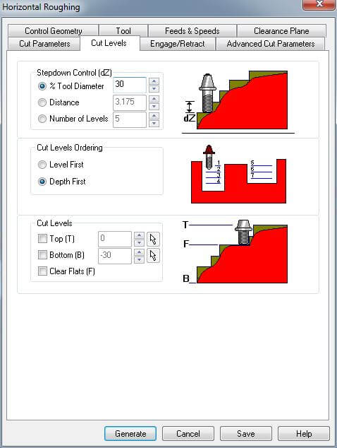
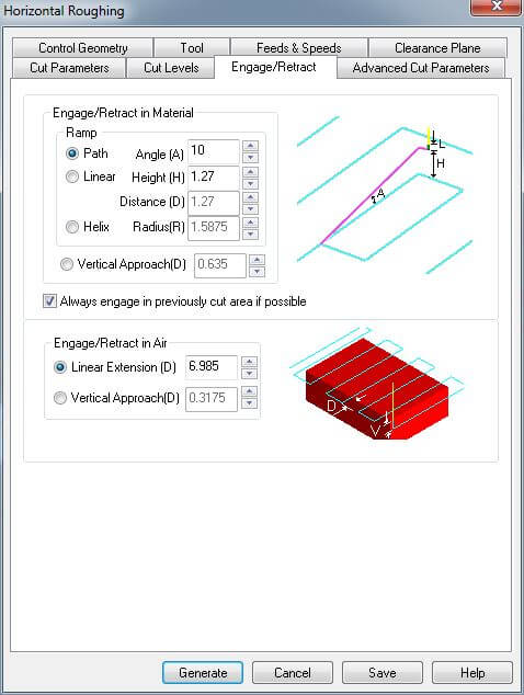
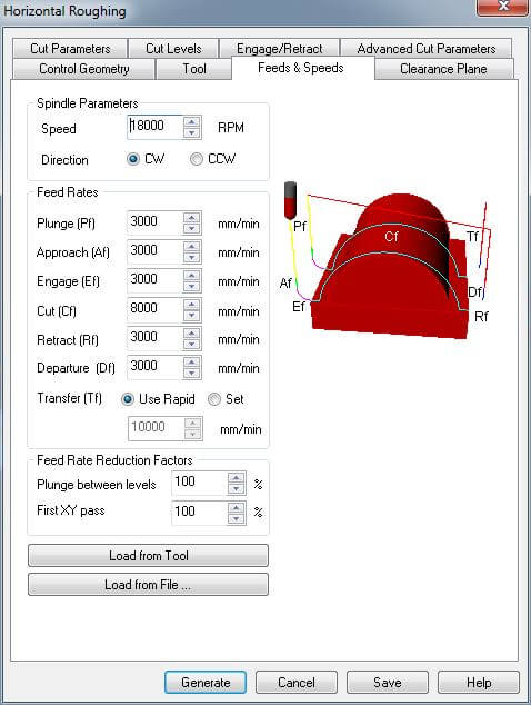
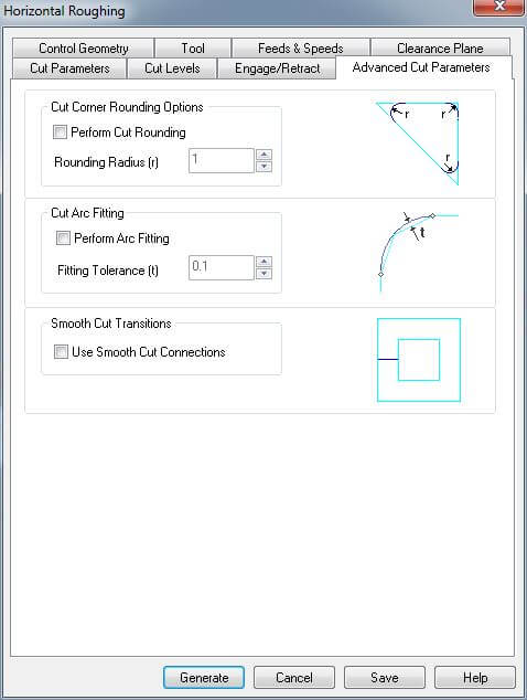
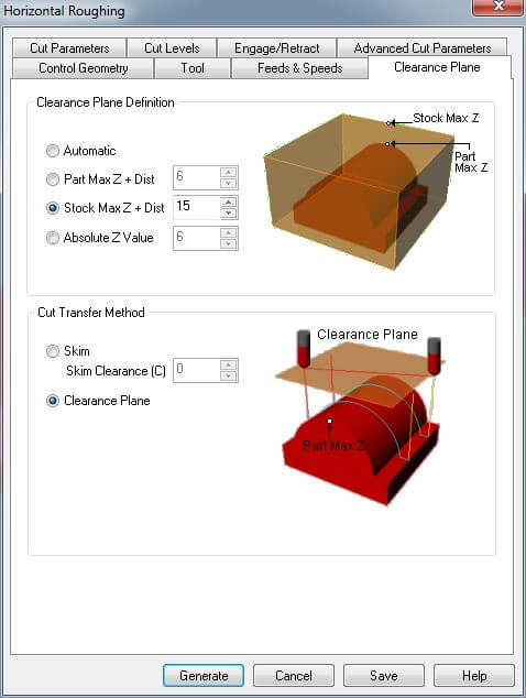
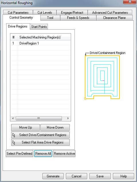
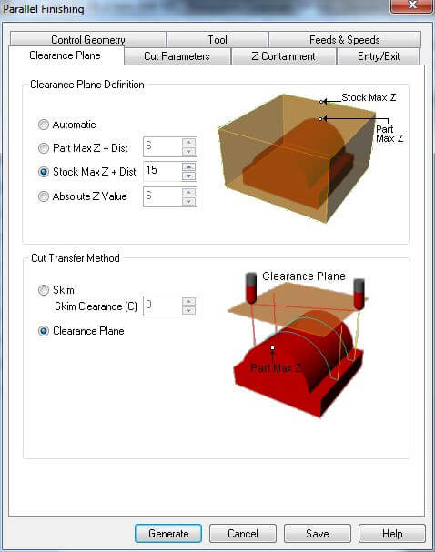
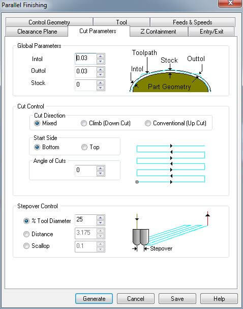
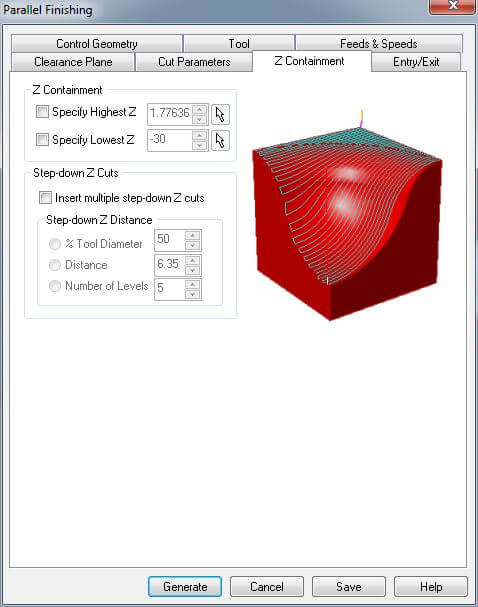
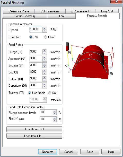
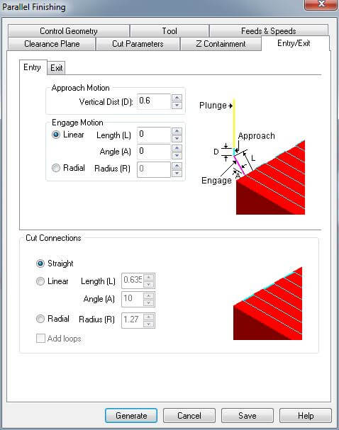
Then, I used a pocketing operation for the join and the head of the Ukulele. For the 3D part, I used a Horizontal Roughting operation first to get reduce the material to cut faster and then a Horizontal Finishing operation to get the a finish and acurate cut. To get the final piece I did a profiling operation to cut the hole pieces. This is the simulation:
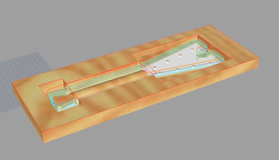
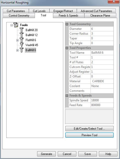
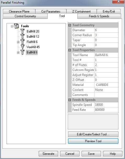
In this case, I used a ∅6 mm flat end mill for the roughing and a ∅6 mm ball end for the finishing. The feeds and speeds for the roughing were the same as the previous ones, but as it was a 3D cut it was important to set well overlap and the cut depth. I used a 30% of the tool in both cases to not force the tool to much. Then with the finishing, I had to calculate again the feeds and speeds. In that case the end mill had 2 flutes so for 18000 RPM the speed was 10000 mm/s. It was too much speed and the machine had a high speed spindel and we cannot reduce the RPM's, so, with the lab manager, we decided to set a 8000 mm/s base speed and increase it during the execution if necessary. Those are the parameters used:
- Horizontal Roughing operation
- Horizontal Finishing operation
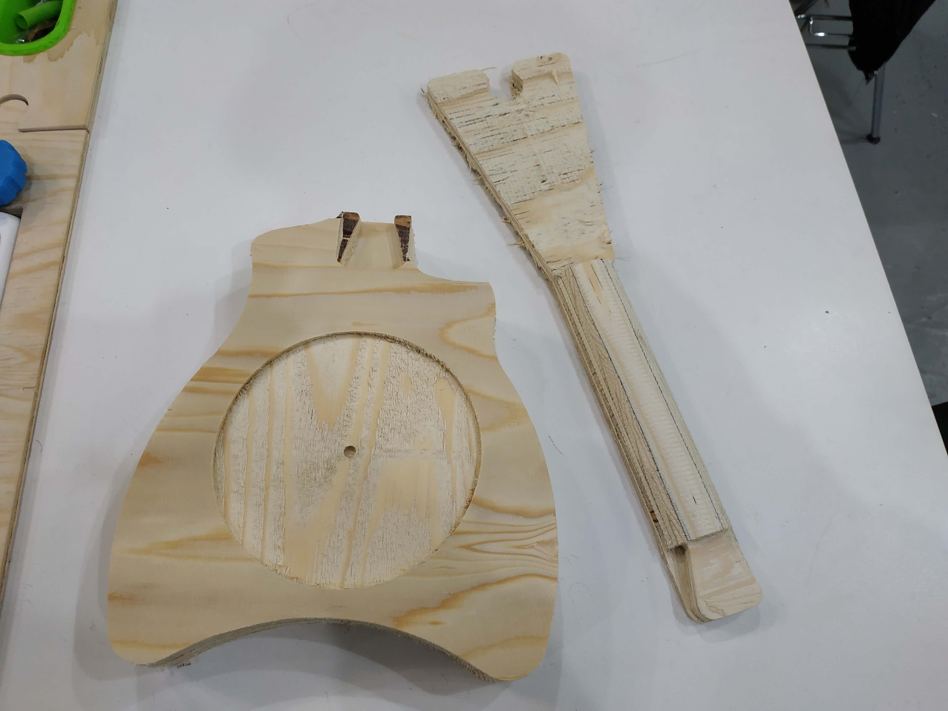
Body Hole
To finish with the Ukulele I made a hole to the body to act a resonator. It used a 3D cut and I use the same process as the neck, first a roughing operation and then a finishing cut to make it smooth. In this case I used a ∅12 mm flat end mill to do the roughing to make it quick and also because I needed a long tool because the body is 45 mm height. For the finishing operation I used a long ∅6 mm ball end mill borrowed from my insructor Eduardo Chamorro.
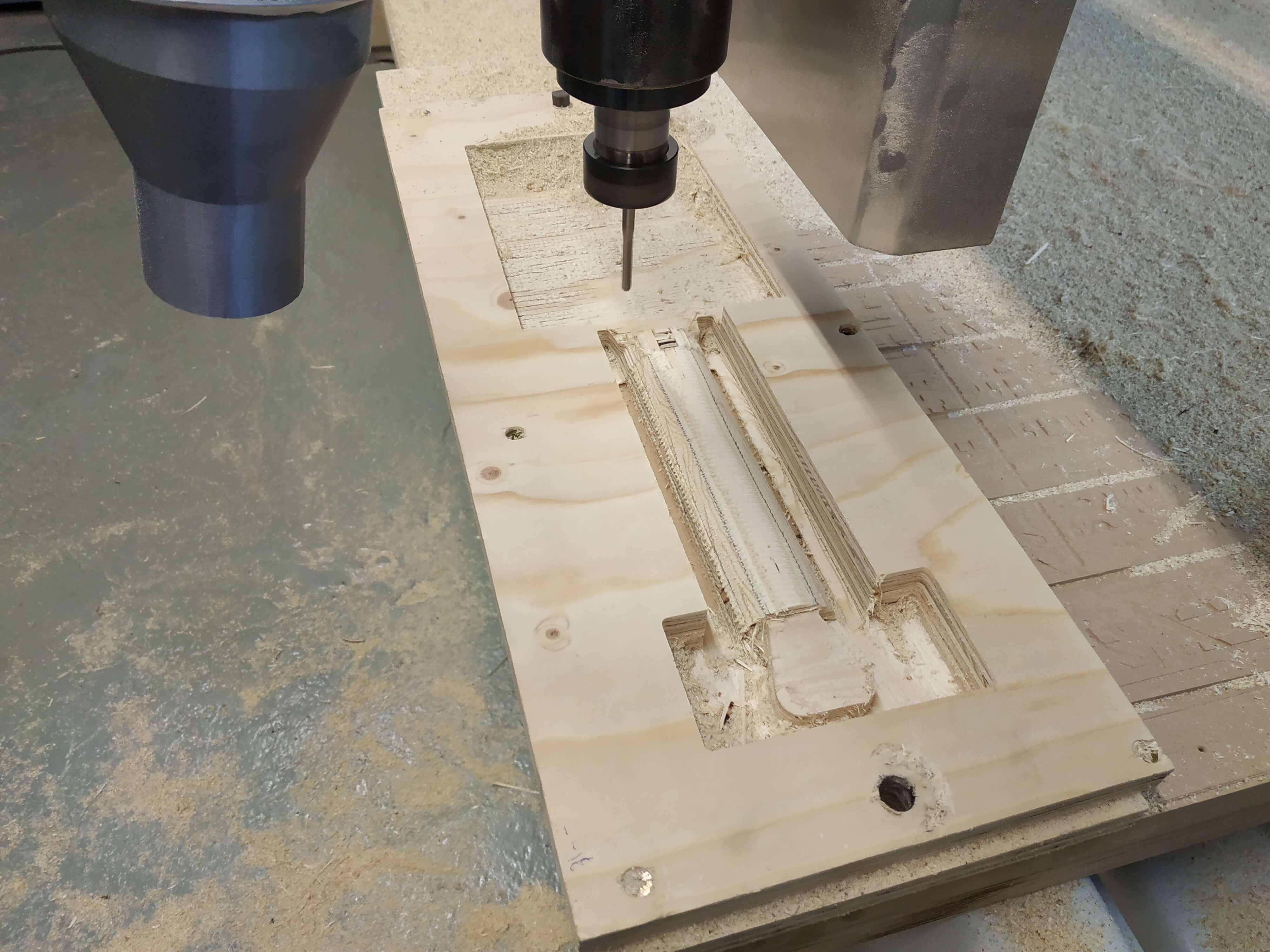
CNC milling
It's time for CNC! With all the files prepared I decided to go to the machine and start cutting. I did it in a specific order:
- Screws
- Join tests
- Body
- Neck first Side
- Neck Roughing
- Neck Finishing
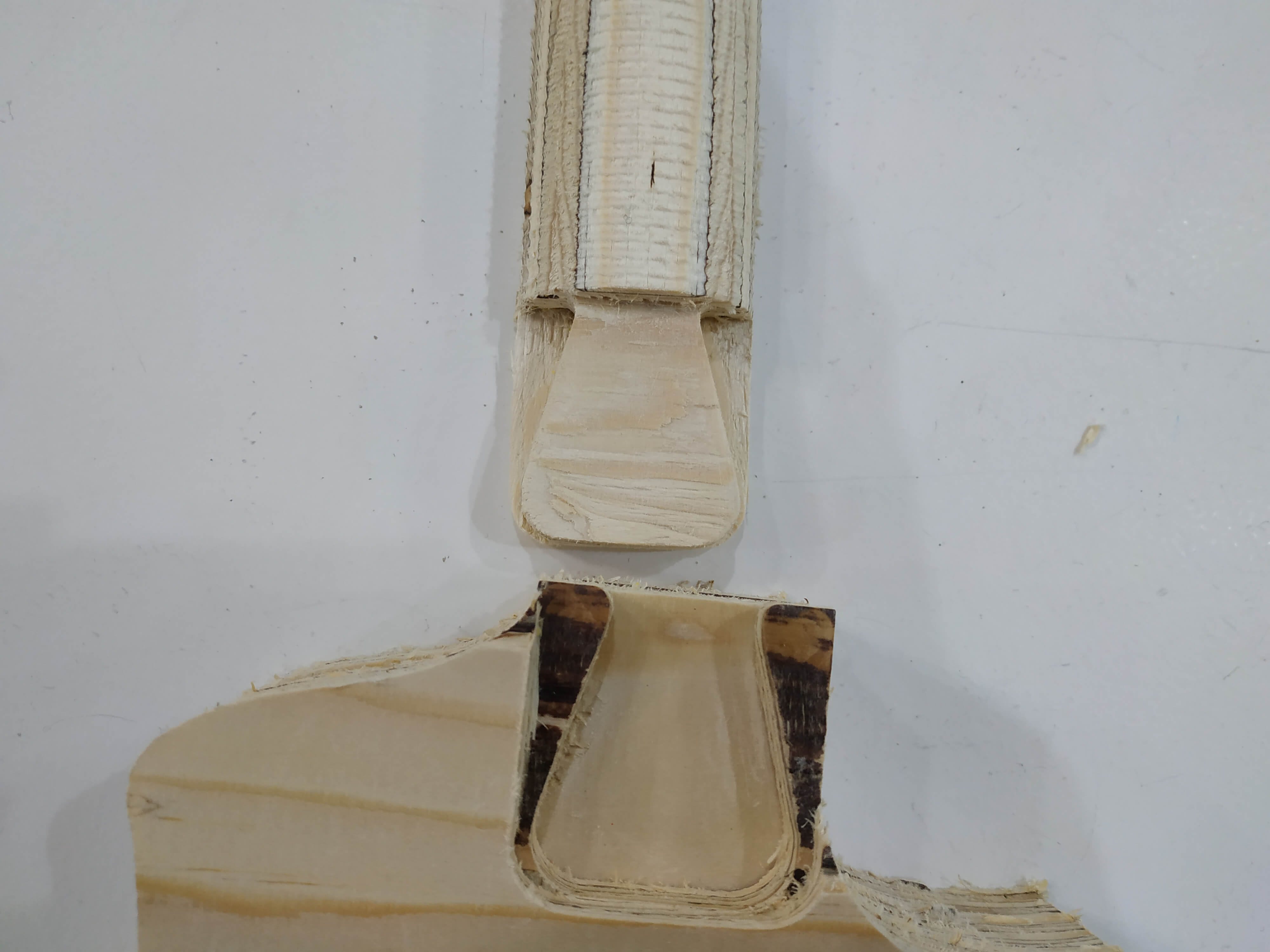
I tried different tolerances and I get that leaving an offset of 0.2 mm for each side of the join was perfect, the pieces can go in with some force and are very difficult to take appart.
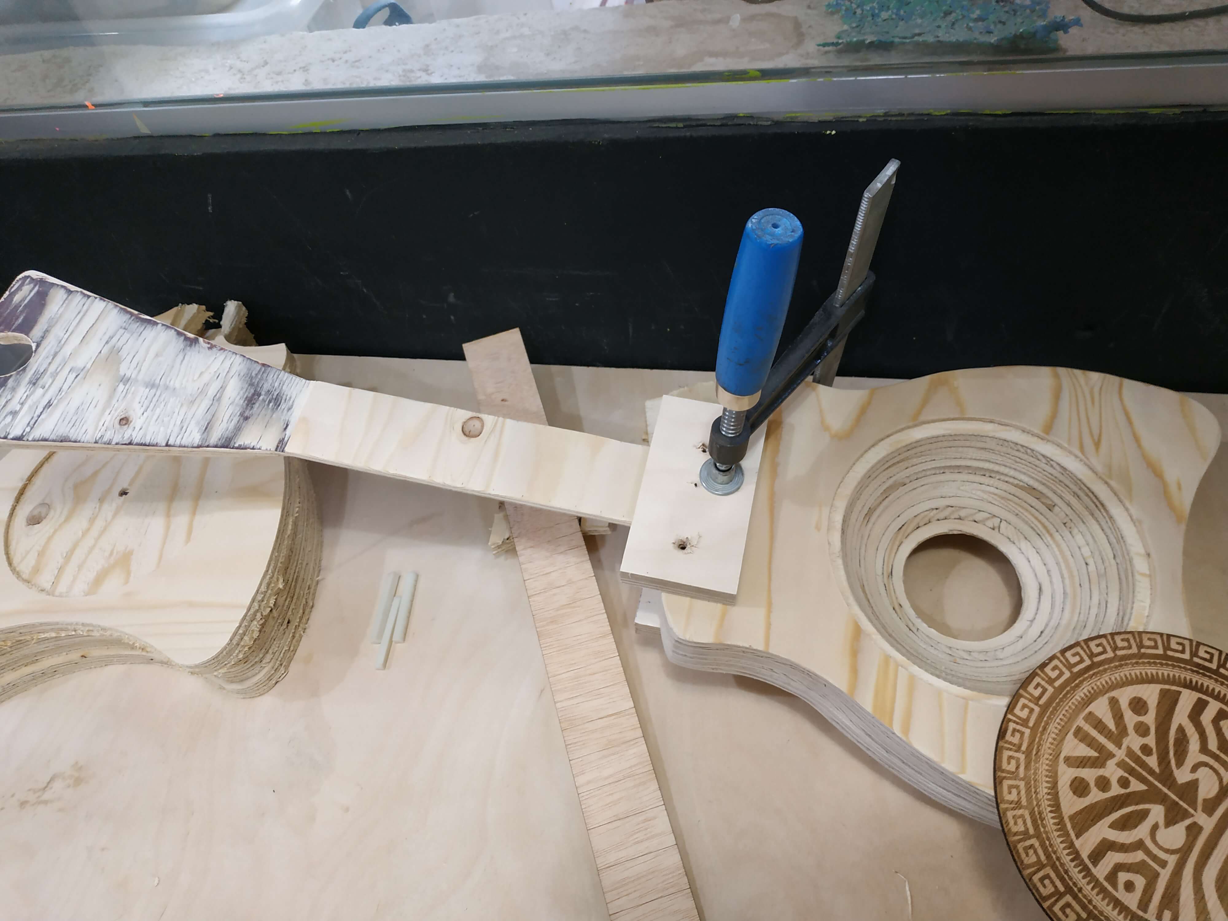
After milling the different parts it was time to glue the pieces together with white wood glue and clamps to hold it together for one day. Also, I decided to start with the sanding process to get a better finish of all the instrument.
Then I changed the material.
Change the end mill to ∅6 mm ball end.
This was the result:
Put my glasses and ear buds on and start the work! Allways stay looking at the machine to ensure that the cut goes well and there is any prolem. Also, for security reasons, I took the dust collector out of it's place to ensure it doesn't collide with the wood doing the 3D cut's.
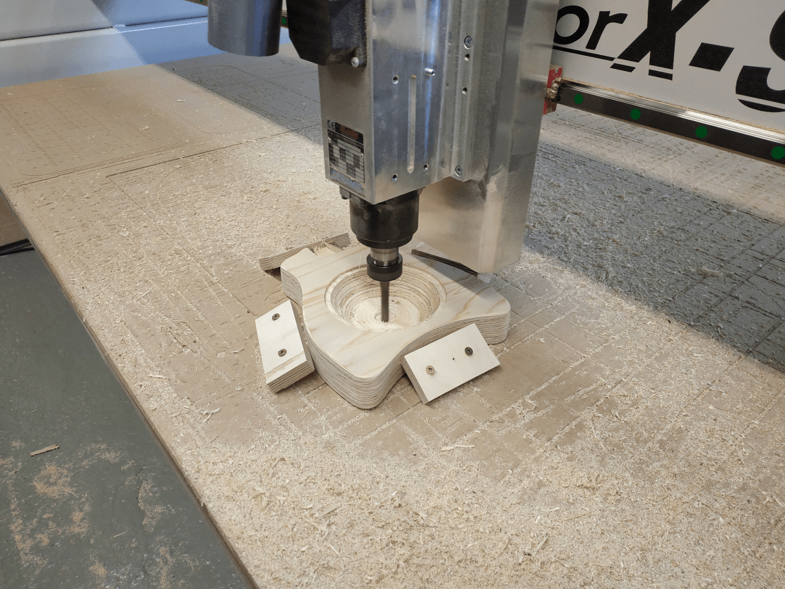
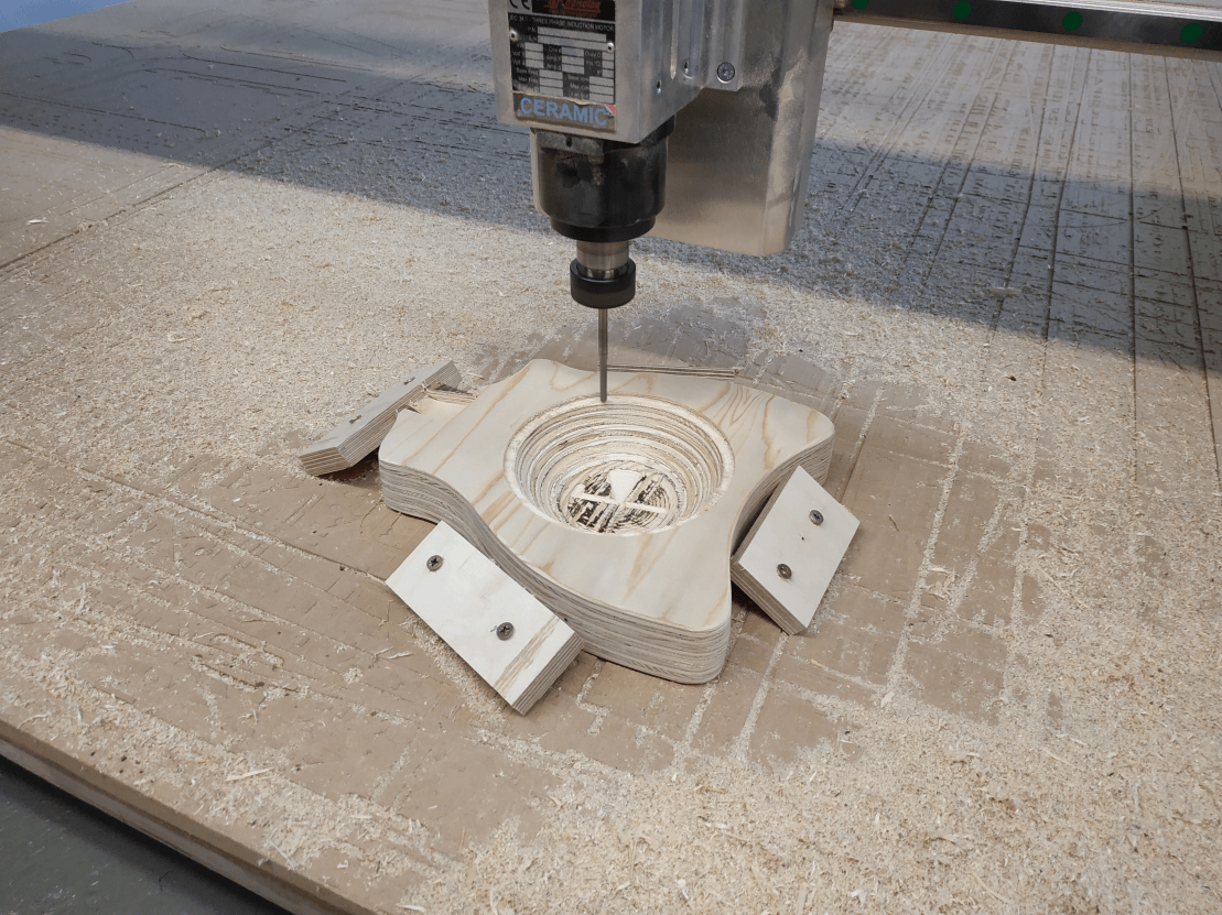
Finally, with the body glued, I did the 3D cut inside the body using a ∅6 mm flat end mill for the rough cutting first and then a ∅12 mm ball end mill for the finishing. Note that I used four pieces of spare wood to fix the body to the table.
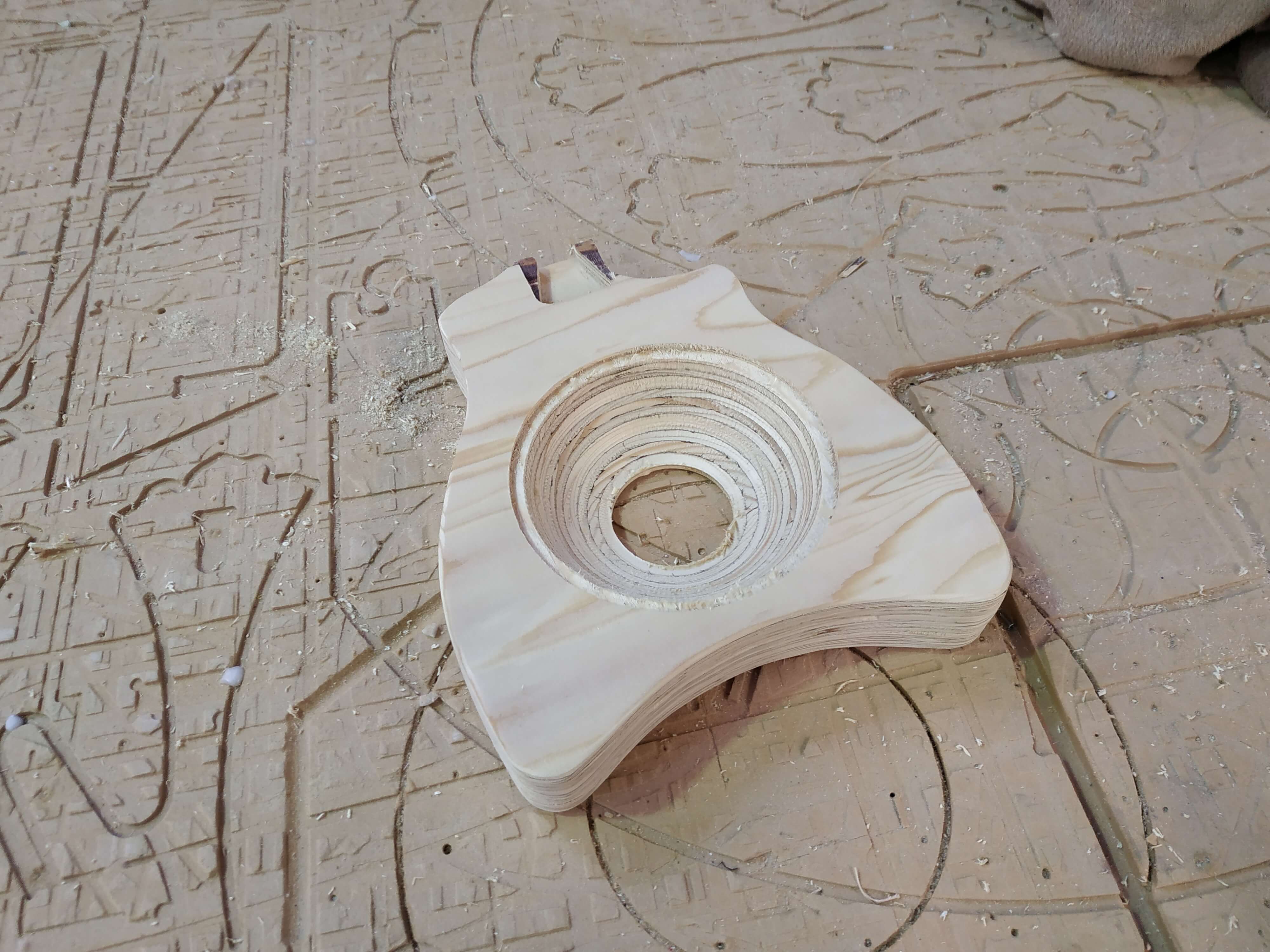
With all the pieces milled, I decided to join them. I added some glue as the join has to take a lot of effort because of the string tension, but the join was really fit and I needed to hammer it inseide. Also I sanded the full instrument to get a nice finish.
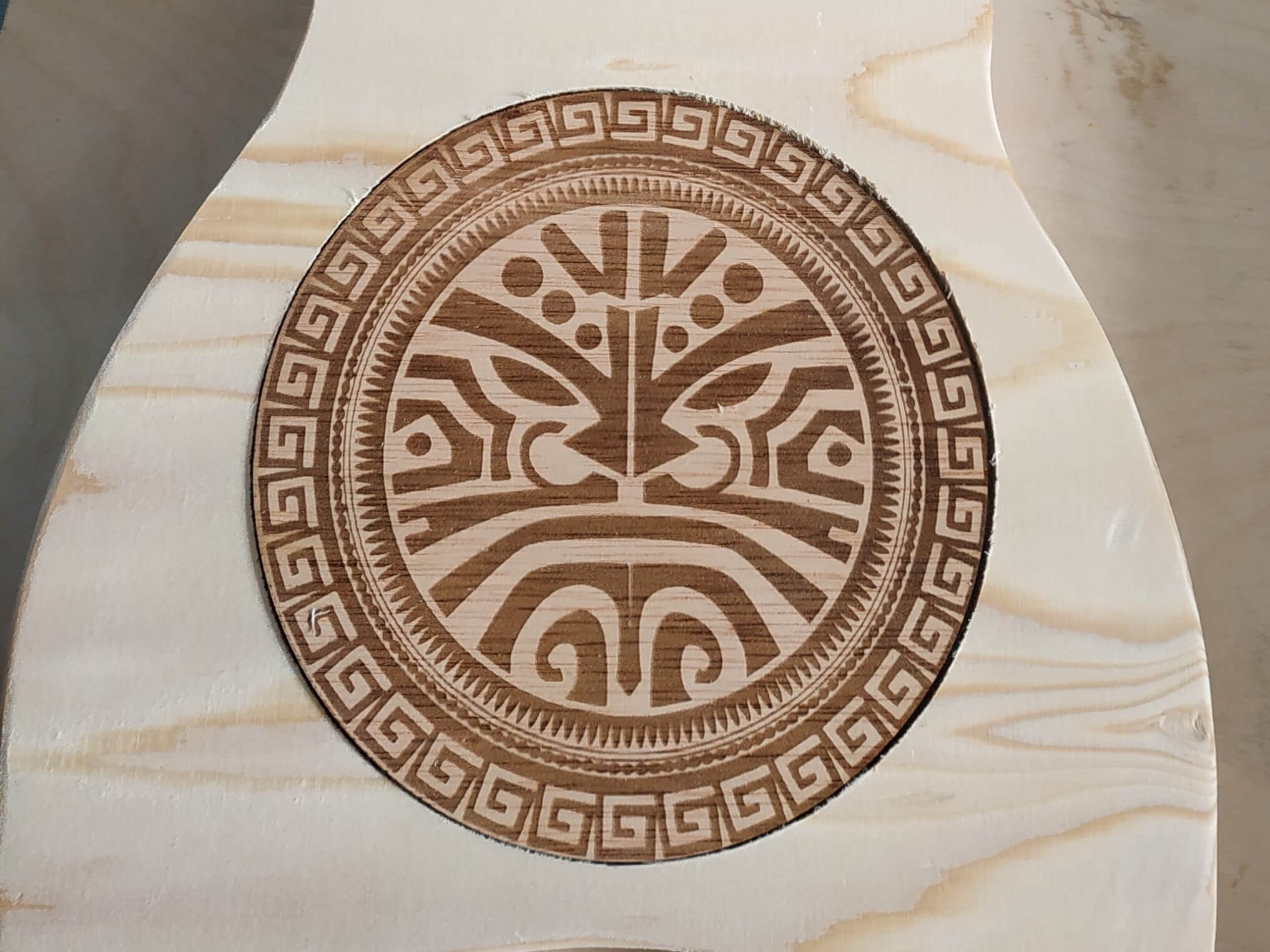
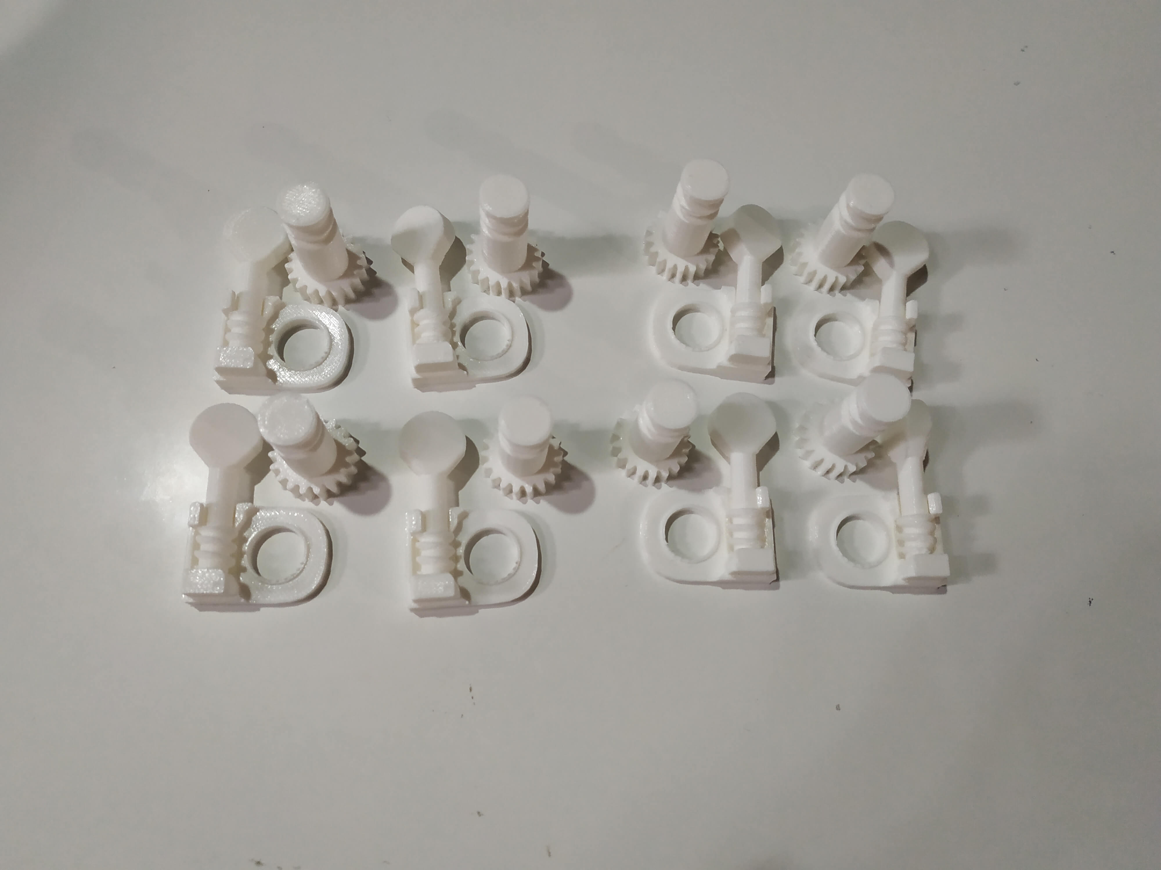
Extras
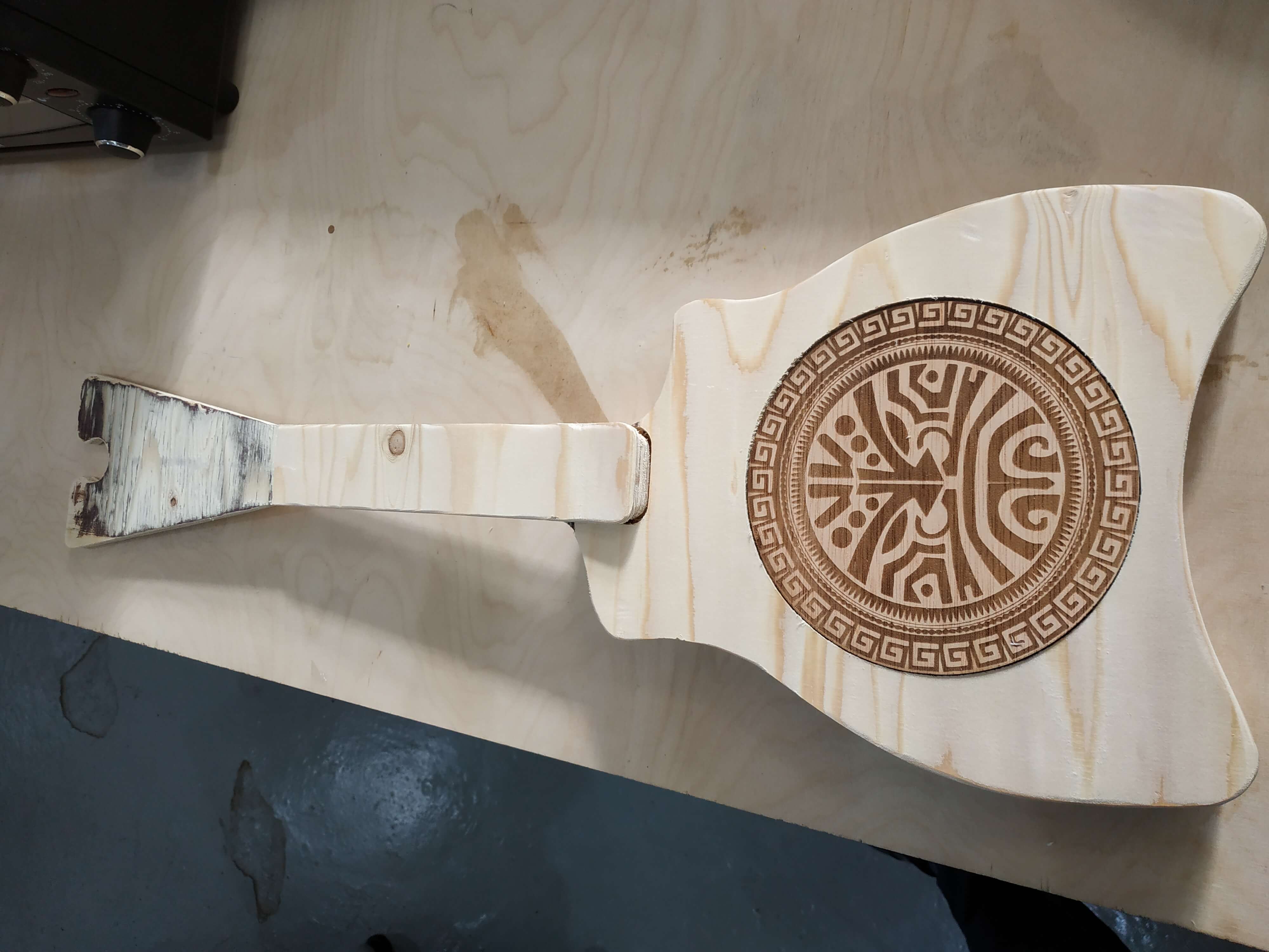
Once the instrument was done, it missed some important parts and I decided to produce them with other technologies that we have learned during FabAcademy. First of all I decided to laser cut and engrave a circular wood cover for the resonator hole. I decided to go for a Tahitian engraving to honor their roots. In the other hand, I used the 3D printer to procude the nut and bridge to hols the strings above from the neck and also the tunning pegs, using a model from thingiverse and changing a little bit it's design. For the strings I used 40 lb fishing line as the tradition says and I also used it to make the frets tacking some inspiration from the Bağlama where they use fishing line to make intermediate frets.
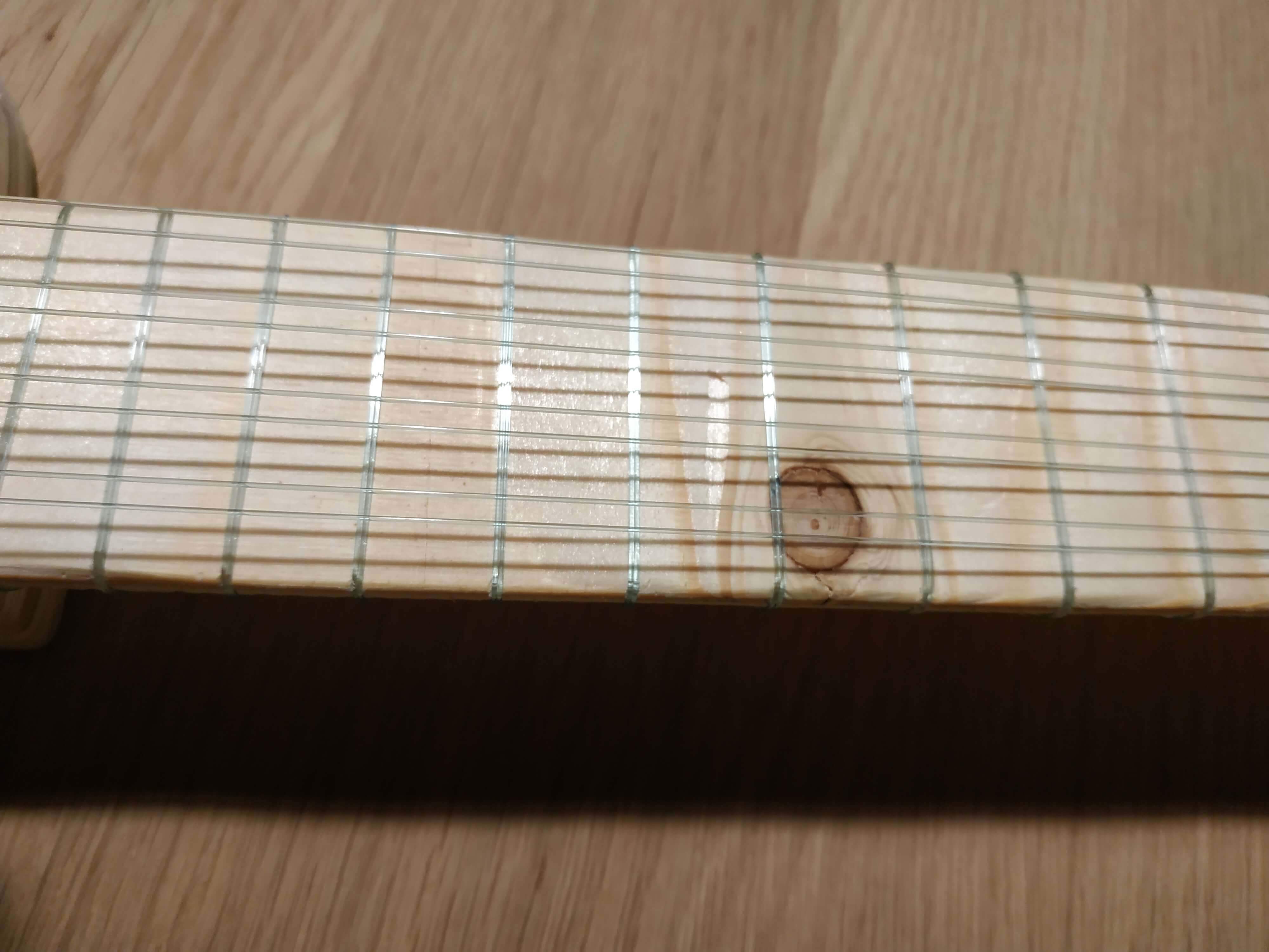
It sounds so... I did my first instrument! It was not perfect at all, it's sonority is not the best and also I didn't reach the highest notes of the tahitian ukulele because the tunning pegs didn't suport all the tension, so I finally tune it up as a traditional Ukulele. I am proud of my work, but I really want to keep making instruments and get a good sound out of them.
Final result
This is the final result!

Conclusion
This was a exciting week. The CNC machine allows you to do a lot of things and really big things, so it is the perfect tool to work with big prototypes fast. It needs a lot of manual work to get a good finishing and it has some limitations, you have to design things very well and do several tests before try your own model, but it is really nice to work with it. Also, for me this week was amazing because I made my first instrument and I learned a lot out of it and for my final project. The worst thing was the time, with only one week and many other students waiting for the machine it was difficult to get the job done on time, so I spend more than a week with it, but it really worth it.