experimentation
make it happen
The challenge for this weeks was “olny“ group assignment and so we have to design a machine to be operated manually. We decided to build a primograph. //just fyi - this happend back in the 2016.
Group members: Elissa Sophia Assaf, Norma Deseke, Andreas Kopp
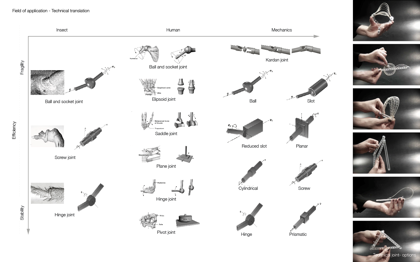
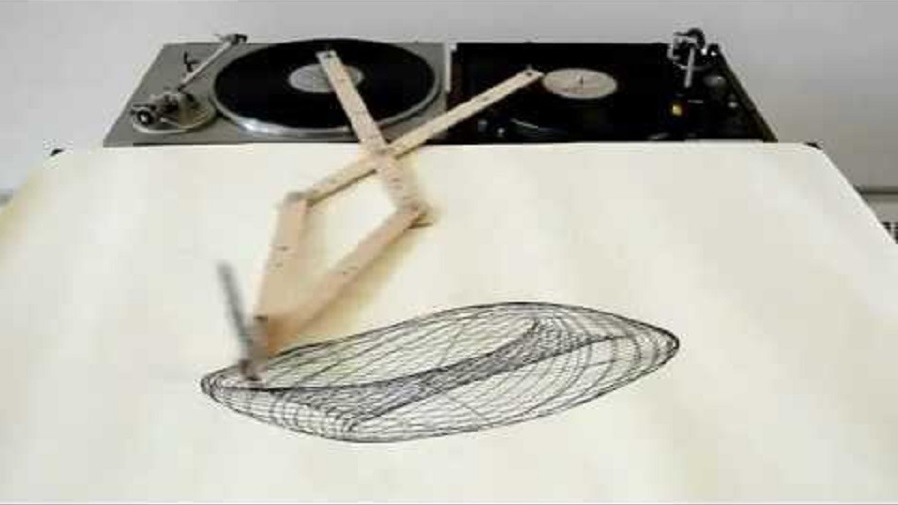
Inspired by my previous kinetic research coming from my past semester project from the University of the Applied Arts in Vienna - ITUS The goal was to observe a biological phenomenon, get inspired by its characteristics, analyse its specifications and evaluate those principles on new architectural design proposal. Our aim was the development of kinetic spatial organisations and how to add them to the existing structure of the london design museum by looking at biological systems and their transformative performance. Observation of insects, their exoskeletons, segmented bodies and jointed limbs inspired us to explore possible options for different technical translations. Furthermore, exploring insect motion led us to develop our own movement logics based on the analysis of primograph and harmonograph ideas. The apparatus of the harmonograph draws a continuous curve based on the movement of three arms representing x, y and z coordinates, generating a 3-dimensional object. it represents the controlled relationship between visual harmony and mathematical ratios. Looking deeper into kinetic arms, hinge trajectories and their simple movement creates complex visual outputs which led us to create the object. from object to the field, the object becomes part of the composition acting like a kinetic transition from exterior to interior. the motion generated by different movements of each arm creates a choreography that represents a gradation of space and continuous transformation. through dynamic compositional elements space is reorganized, creating new modes of use and experience within the environment.
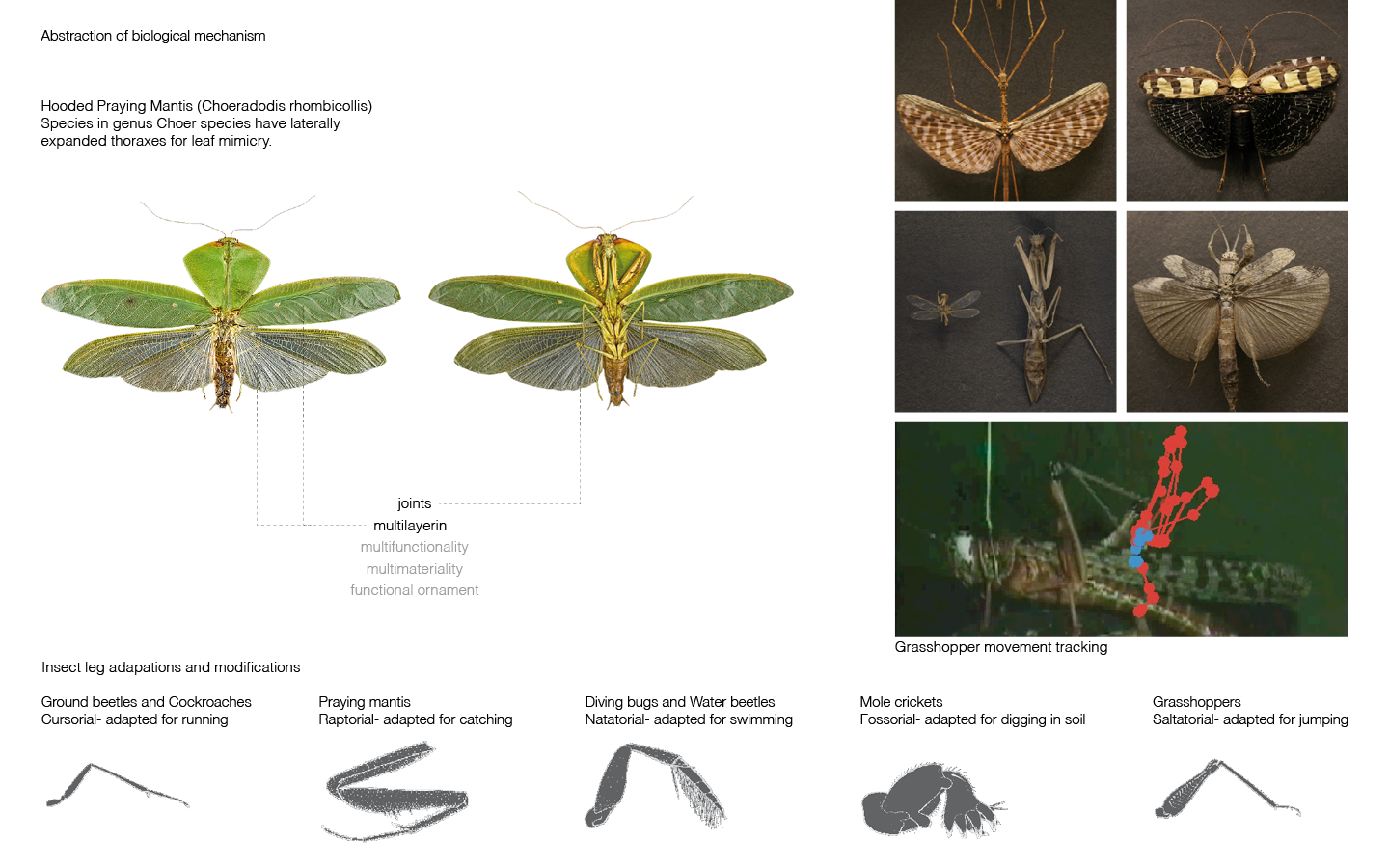
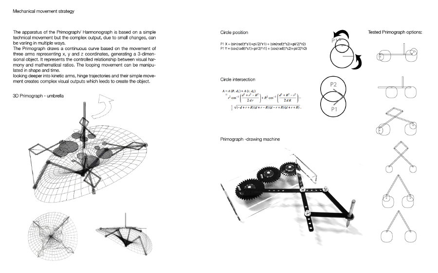
Images showing the previous explorations from my uni project, explaining also the mechanical movement strategy of primograph machine.
Tools and Materials, CAD to CAM Process:
Software: Rhino and Grasshopper Test Machine: Epilog Legend Laser Cutter Test Materials: black and white Acryl, 3mm Final Machine: Multicam 2000 Laser Cutter Final Materials: MDF Wood,4mm Other materials: 10 screws, 21 nuts, glue
Inspiration and Research:
One inspiration for our project was the "Drawing Apparatus" by Robert Howsare, a primograph created from two turntables. Another stunning installation came from Copenhagen based artist Eske Rex created a drawing machine generating beautiful artwork. Eske Rex: "Drawing Machine is a construction involving two pendulums, each suspended from a tower construction and connected through “drawing arms” and moveable joints. A ballpoint pen resting on a drawing surface covered with paper is mounted at the point where the pendulums come together. The pendulums are set in motion by hand, and their movements are represented on the paper. The Drawing Machine serves two purposes: On exhibitions where the movements of the pendulums affect the entire room, and the experience engages the beholder’s body. While the rhythmic repetitions cause the beholder to pause, the drawing emerges on the paper. And as a tool where investigations on the relation between time and movement."
Computer Aided Design Process:
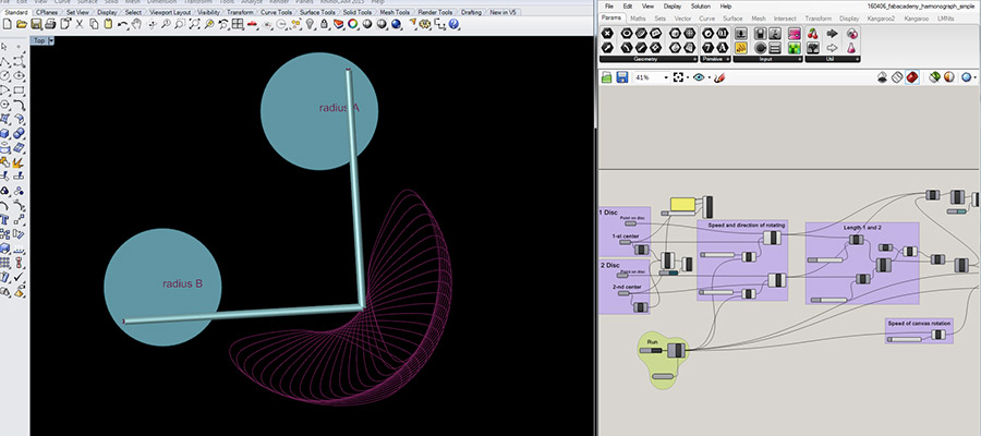
Rhino/Grasshopper - screenshot of the primoraph design. GH definition allowes the adjustments of the lenght of arms and circle diameters, those changes of parameters are resulting in different output drawing pattern
Primograph simulation in Rhino using plugin Grasshopper - this is a screen recording of the definition that I saved on the computer in the Fab Lab. Elisa documented this on her vimeo profile.
Primograph simulation using an App in the mobile phone done by Andreas. It was also saved on Elisas vimeo profile.
Material, Machine and Tests: * 3mm black acrylic: 15-100-5000 (speed power frequency) on Epilog Legend Laser Cutter (load file, press 8- xy off, press go; move home manually; press 7 - adjust; press 9 - focus; press go) * First test: didn't cut through * Second test: decrease speed to 4%, still not cut; cut same place twice with same settings: cut but edges burned, would affect wheels and translation of movement. So change material. * Third test: white acrylic also 3mm, 15 speed didn't work, 5 works, nice clear cutting edge. * While it worked in the final test, setting out to cut the whole box failed. This was either related to the uneveness of the machine surface base or varying material thickness? Settings worked in some but not all parts of the material.Idea to use wood for arms and wheels, but based on previous tests wood has a texture which renders movement less smooth, whihc would impact on wheels trasnlation of forces (movement). We try anyway.
Change of Material and Machine: MDF Wood on Multicam 2000 Laser * The cutting worked fine, however when we assabled the box, we realised that we had misplaced the gears, they where actually not touching. So we went back to the design file and relocated the gears (Rhino). So we recut the box and assambled it.
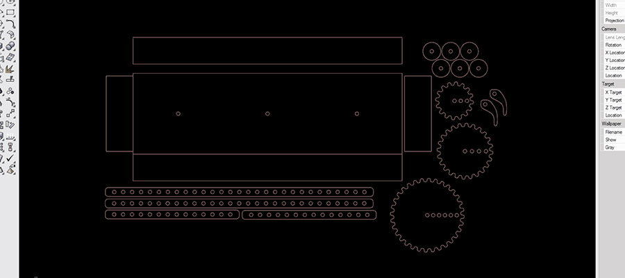
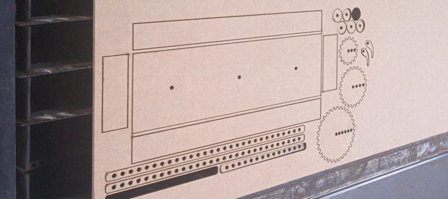
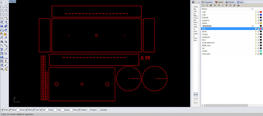
file before - layout of vector drawing for the laser cutting, on Rhino, before exporting to Job Control ready to laser cut!
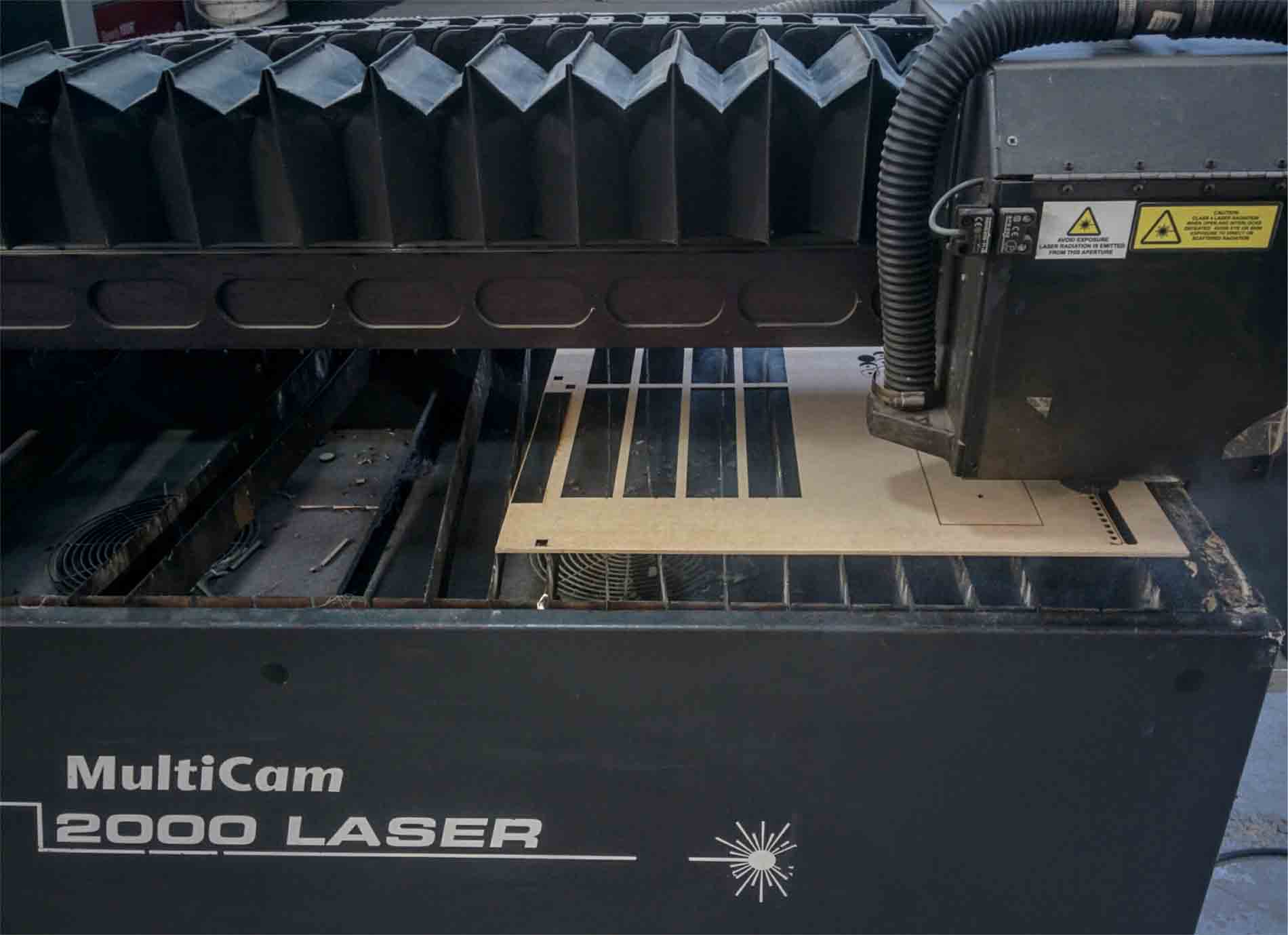
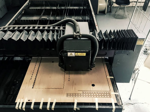
multicam laser cutting
...after the laser cutting job was done...still in the machine...
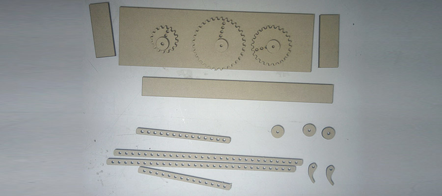
individual parts of our machine...waiting to be assembled all together
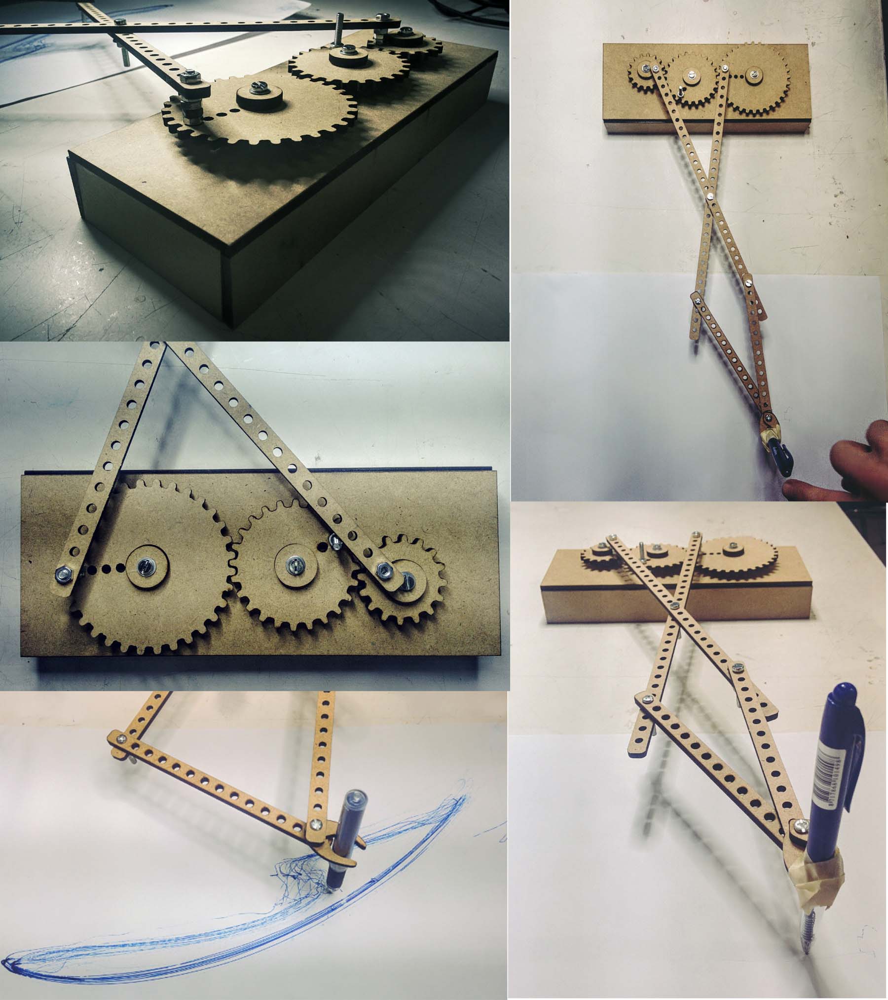
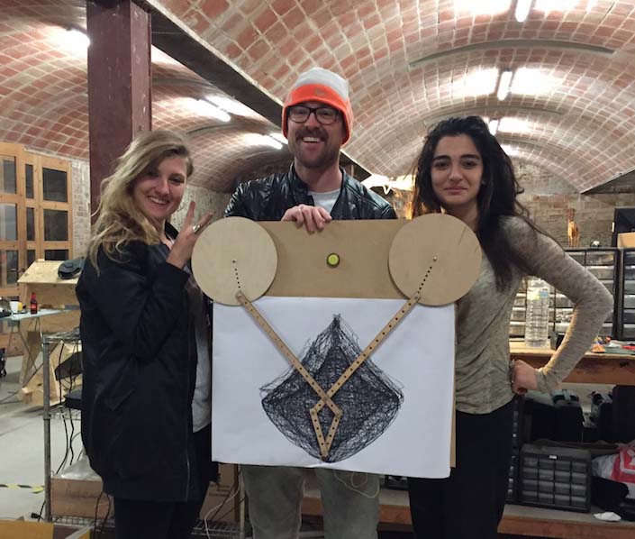
final result - our primograph machine finally made it to see the light of the world! Yeah! So we tested it! and it works! So proud on my team!
The prototype works, however, there is lots of room for improvement: * The pen holder doesn't do its job (duct tape is a sign of failure!) * A bit instable and wobbly (we need to locate the grip to move the mechanism differently. * Improve gear mechanism to generate different more interesting patterns. * Decision to be made wether we build a one motor or two motor mechanism: 2 motors with different speeds for different patterns/ 1 motor might not be powerful enough to move both gears.
Video of the drawing test.
Our project page from Fab Academy 2016 you can find here
Task division: Elissa - assistance with 2D/3D detailing, 3D printing, machine assembly, Norma - documentation, Andreas - code creation and programming, Me - concept + 2D/3D design, procedure coordination, Laser cutting, 3D printing, machine assembly
Individual contribution:
Being more specific, my individual contribution to this group project was the initial concept idea for machine creation, as already mentioned from the beginning, it crystallized from my university project dedicated to the exploration of kinetic movement inspired by the chosen biological phenomenon. So I brought the idea of building and automating the primograph drawing machine and the rest of my team liked it. So I was guiding them throughout the previous explorations, introduced the idea of joints, relations of different dimensions for length of arms, radius, and speed variations relating in the final representation - drawing. Since I have already tested and documented changes of various parameters and from those, I created a library of drawings, together with my team we chose our favorite drawing and the challenge was to try to reproduce the pattern with our primograph machine. So I provided all the necessary input data as Rhino File with grasshopper definition, I installed all necessary plugins to the Lab Computer that everyone in my team was able to open the file and have a look at it, understand it and evaluate next steps. I also asked Elena to do a screen recording for visualizing the movement in Rhino environment. I designed the box with arms and wheels/circles in Rhino and then laser cut them. Elisa was assisting me, she designed the pen holder. Together we were testing it.
download files
So since this weeks assignment I did in 2016 and now in 2019 it is merged as a documentation in one page, I continue below:
For this week´s assignment we have to automate the primograph machine we designed previously in the mechanical design week. We brainstormed the design and functioning of the Machine together and settled on a plan of action. Norma kept track of the work processes for our documentation and conceptualised further development of our automatic primograph. Together with Elisa we did most of the 3D modeling in Rhino and Blender, Norma contributed the boxoutline in Inkscape. Andreas focused on electronics and software and a little introduction using the pi and the explorer hat. He prepared the two motors and explained to us how to incorporate them with Rasperry Pie and the gears. Together we did the laser cutting, 3D printing of parts and assembling.
Being more specific, my individual contribution to this project was:
Software, Materials & Machines
Software: Rhino and Grasshopper; Inkscape; Blender Machines: Multicam 2000 Laser Cutter; 3D printer Materials: MDF Wood,3mm; Fillament Other materials: screws, nuts, 2 DC motors, Raspberry Pie, button including a LED.
Improvement of Prototype Design:
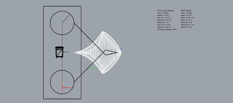
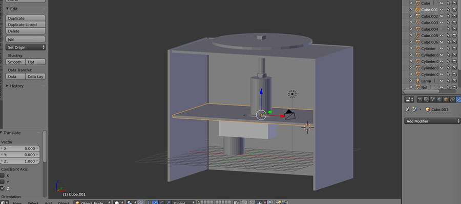
Above you can see the screenshot of Rhino model of the primograph and its drawing pattern that was choosen to be replicated. To improve the accuracy of our machine, we now have two detached gears, instead of three interconnected ones. We increased their size to 200mm in diameter. They are operated by two motors respectively, which increases the level of control. We can now change the speed of each gear independently. We decided to do this to create a certain drawing pattern, that we picked from my previous kinetic research that I was explaining back in week 14 and that we liked most. Additionally, we increased the length of the longer arms to 380mm each, and the shorter arms to 100mm each. The pen holder is now one piece only, with a polstering of foam. We further redesigned the size of the box container itself (800mm long - 300 mm wide - 150 mm high; material thickness 40 mm) to adjust to the new messurements of gears and arms. To include the motors and add stability, the box has three layers: the top layer has the one/off button and holds the gears, which are screwed to it. The second leyer stabilises the gears. The third layer is the bottom of the box, which has the motors attached, screwed onto it. The gears are connected to the motor with a 3D printed "pipe" system, that contains long screws. Additional 7 screws hold the top parts mechabism together, another 8 screws hold the middle and bottom layer and fix the motors in place.
Issues while machine design procedure:
We were supposed to add another nut in the hole on the bottom part and tighten the 2 nuts to fix the gear part to the motor but the screw wouldn't fit in the hole of the 3D printed part so we had to redign and print it. * Design and Materials: Our design was based on MDF Wood with 4 mm thickness, but we ran out and had to redesign the Rhino files for laser cutting to get proper dimensions of 3mm material thickness instead. * Laser Cutting: Didn't cut through everywhere, because the board was bent. So we had to cut some pieces twice. However, now the screwholes on the arms were a little bit too big, which would result in a wobbly arm mechanism. So we cut the arms again. * Design and 3D Printing: 3D printed parts broke in the assmebling process, its top sides were too thin to withhold pressure.
ready to cut - layout of the vectors before laser cutting. next step is to export it and print it ti Job Control to laser cut.
Workflow:
We discussed the design of the mechanism together. Andreas was in charge of the electronics. He connected the two stepper motors with four cables to on7off button and the Rasberry Pie. He extedned the cables and modified the button, so it includes a led to display on/off mode. Based on a previously designed app to controll the motor, he programs the Raspberry Pie with Pyhon, explaining what he is doing to the group. He further explores how to incorporate a slider in the app to controll the speed of the stepepr motor(pulse width modulation). Elissa was mainly busy with the design of the laser cut files of the box with its layers, the beams and the pen holder, working in Rhino. Norma designed a box with finger joints in Inkscape to be incorporated by Elissa into our design file in Rhino, however, it was easier just to redraw it in Rhino directly. I designed the Blender model of the "pipe" system that connects the gears to the motor (screws inside). Norma took the measurments of the motor and passed them to me to generate this model. I also took charge of the 3D printing of parts, such as the holder for the Raspberry Pie (designed by Andreas previously), the connecting "pipe" system as well as Elissa´s design of the pen holder. She did so by exporting the .stl design file into the 3D printing software Cura to generate the Gcode. Norma mainly move between group members, discuss upcoming problems and update everybody on everybody elses´ progress, while collecting and sorting work and documenation files. She also write the HTML documentation, so everybody has the outline of the process, which they can modify for their individual documentation.
Laser cutting process. Box creation in progress.
3D model of the connecting mechanism in blender. We had to figure out how we will connect the motors with arms/gears and this was the solution.
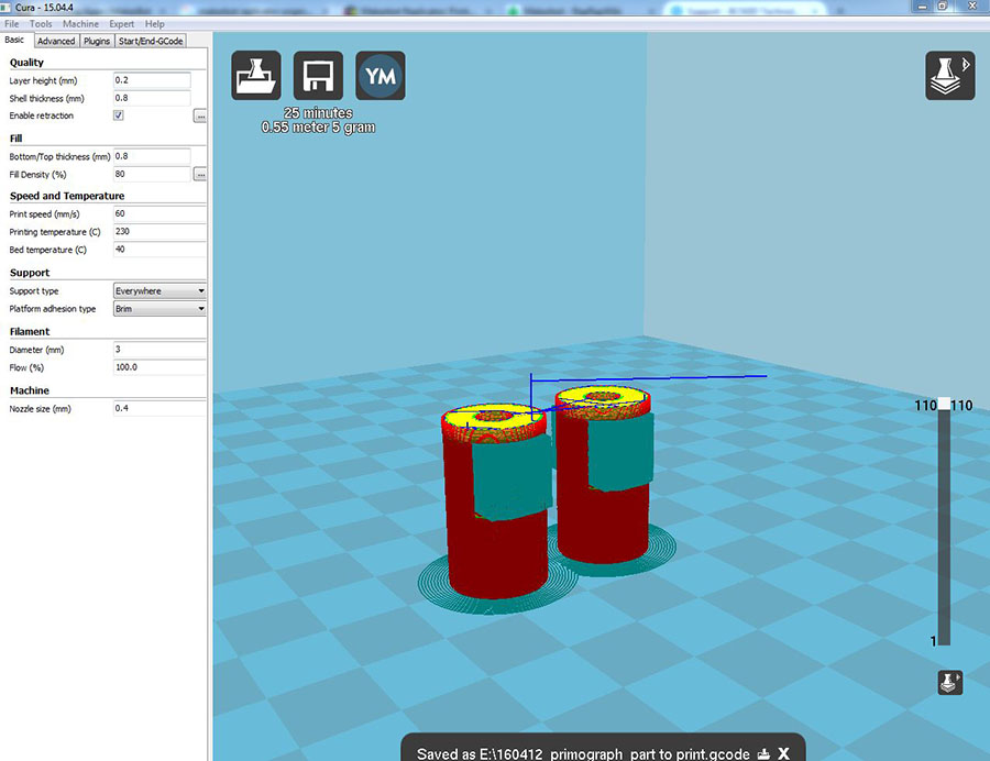
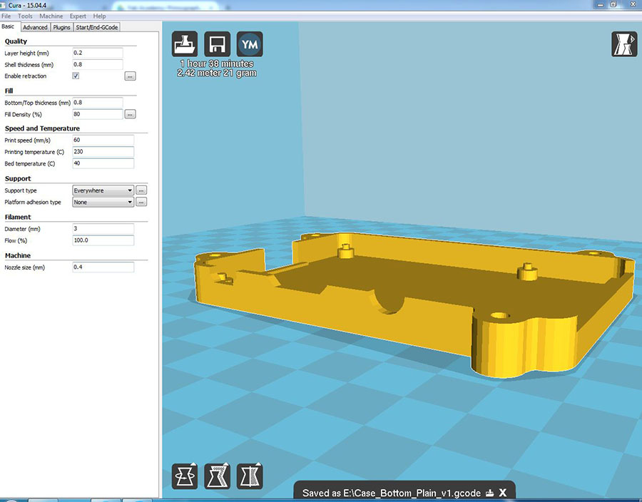
Part connecting the motors to the gears. Image showes the layout in the Cura SW where we prepared gCode.
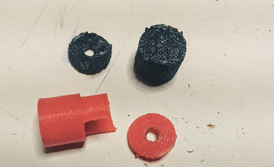
They were too thin so they broke because they couldn't handle the pressure weight and velocity of the motors. So we have to reprint again.
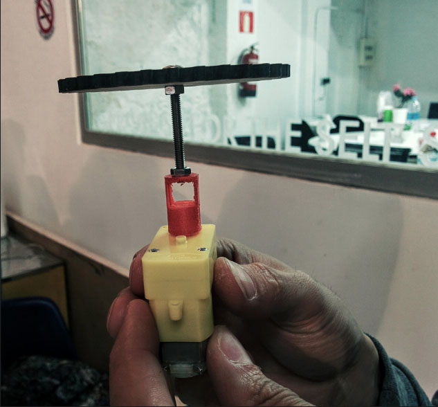
Here you can see how we are using the 3D printed part to connect with the motor.
3D printing of the Raspberry Pi Casing.
Second prototype assembling of the box and arms.
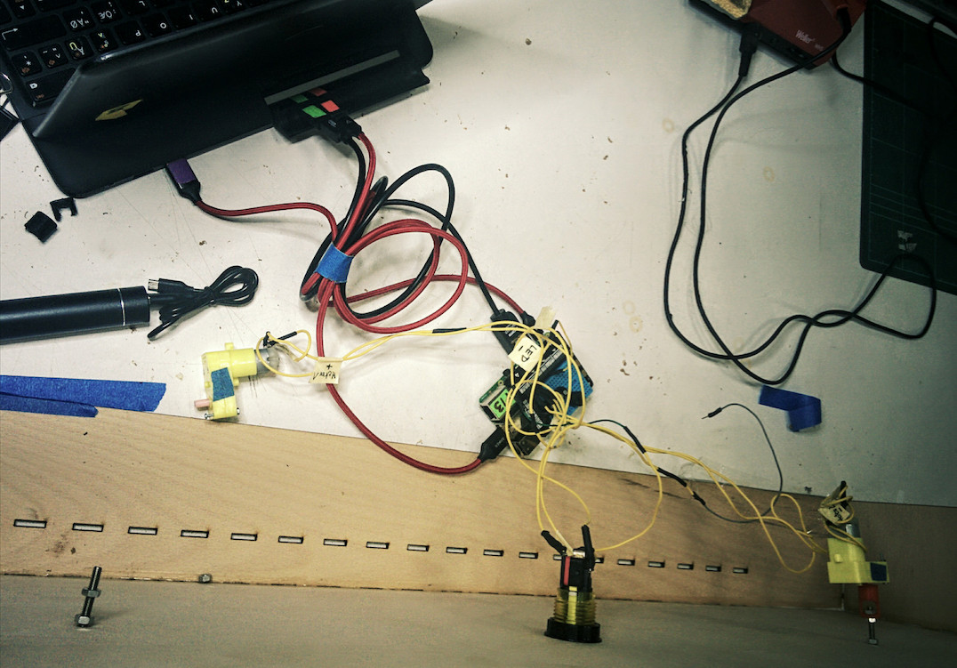
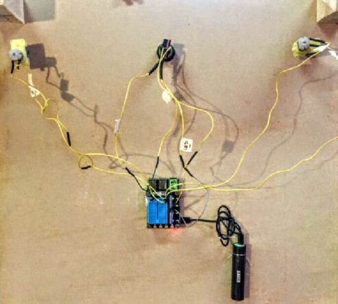
Second prototype assembling - electronics. Assembling the motor, button, led. Ready to program.
Second prototype assembling - electronics. Back of the Machine with motors.
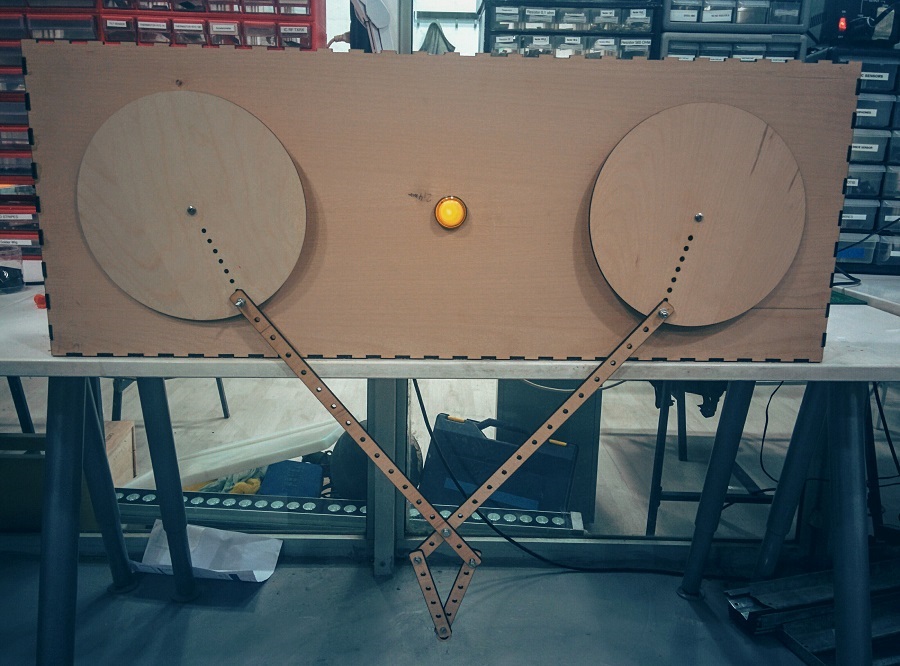
Assembled prototype positioned vertically.
Code
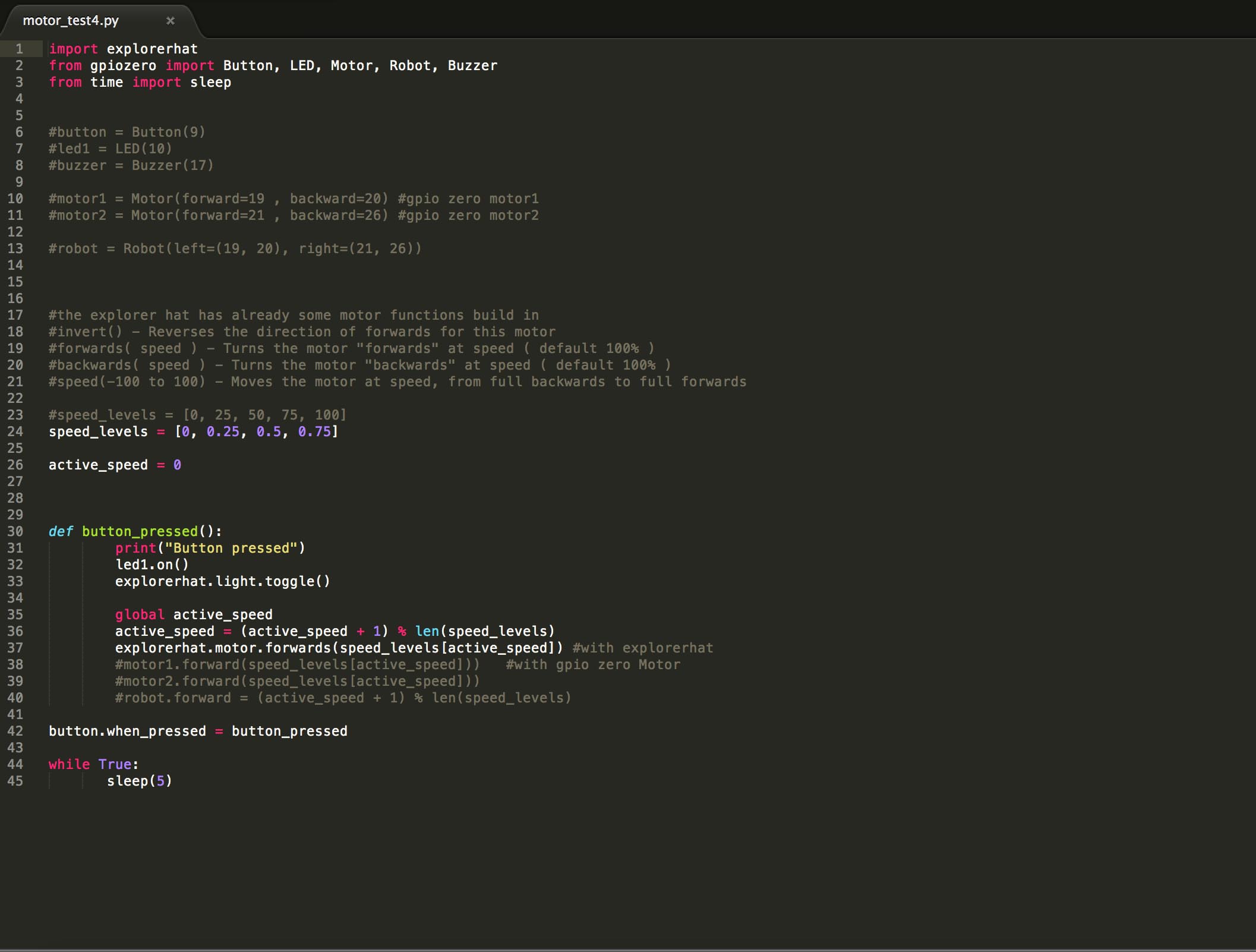
Screenshot of the software running the motors.
The Explorer HAT uses an output driver chip called the ULN2003A, which contains a set of transistor pairs called a Darlington Array. It transforms the small logic signal of the Pi into something capable of driving much bigger loads, such as motors, steppers, lights and more.
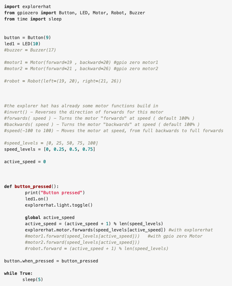
In the meantime Andreas has already connected the Button and the Led of the Button to MISO (pin9) and MOSI (pin10). The complete code you find under Project Files. What it does is when you hit the button you start the motor and when pressing it again you make the motor go faster until its maximum speed and then you turn in off again.
Control the Motor
Andreas also looked at the Data Sheet of the Motor Driver with is a Dual H-Bridge Current Control Driver DRV8833PWP and realized that he could not only control DC Motors but also Stepper Motors and to control my speed with PWM. These are the commands for the Motor we can use. invert() - Reverses the direction of forwards for this motor forwards( speed ) - Turns the motor "forwards" at speed ( default 100% ) backwards( speed ) - Turns the motor "backwards" at speed ( default 100% ) speed(-100 to 100) - Moves the motor at speed, from full backwards to full forwards
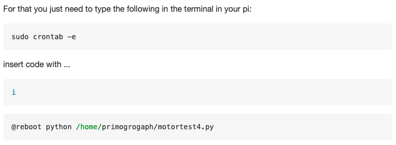
Make everything boot on startup: Because Andreas wanted to make the pi battery powered and make the machine portable he made the program start on startup.