Electronics Production
Group Assignment
Machines
FabLab Barcelona have two different Roland milling machines:

The Roland Modela MDX-20 is a small milling machine and a 2 1/2D precision scanner. This machine is mostly used for milling circuit boards, though it can also mill in other soft materials like machinable wax. For milling circuit boards you should export you design into a black&white monocroome png. For milling out 3 dimensional molds you should export your design as .stl The second use of this machine is scanning. It uses a thin needle to gently touch the object and calculates from this a 2 and a half dimensional model. Though slow at processing, it can create a high detailed model. Work area: 203 x 152 x 60 mm (from Wikipedia)

This machine is capable of cutting a wide variety of materials including chemical wood, acrylic, and ABS. It is also capable of a range of accuracy settings from prototype to product design. Plus its small size and fully covered design allows you to enjoy cutting more safely and with peace of mind. Work area: 203 x 152 x 71 mm.
User Manual
Milling bits

We have two different bits to work with our PCBs.
1/64" - Used for milling the trails on the board
1/32" - Used for drilling holes and cutting the board
Softwares
Our instructors recommended us to test the machines generating files from two diferent softwares: MODS and Fab Modules.
Mods
Right click program, open server program, machines, roland, mill, srm-20, PCB

Steps followed:
- load png file
- select trace or cut
- change settings for the machine to origin 0,0,0 and home 0,0,5 (x,y,z)
- delete the WebSocket module
- add the save module instead
- calculate path
And then you’ll get the rlm file

Fab Modules
Download the line test document linetest.png
Open the Fabmodules:
http://fabmodules.org/
Click fab modules, than index.html and open the format PNG-document. Select Roland mill and PCB traces.
Insert the settings:


Now we did the same procedure with the outline cut, dropping the “linetestinginterior.png” file into the FabModules. We used the same machine (Roland Mill) for cutting the PCB outline.
Then we took the correct mill bit (1/32) for the job and inserted it into the machine, and adusted the z-axis “by hand”.


After that, we set origin point for all axis

Then press “cut” to get to add the file “linetest.rml” and the job will start. Check if the milling goes well, not to deep, not cutting air.
After finishing, just press "view" and it will bring the piece forward. Then we get the milled piece.
In the first milling test, as you can see here, we choosed wrong settings, so the machine was cutting the inner border of the frame:

Compare results:
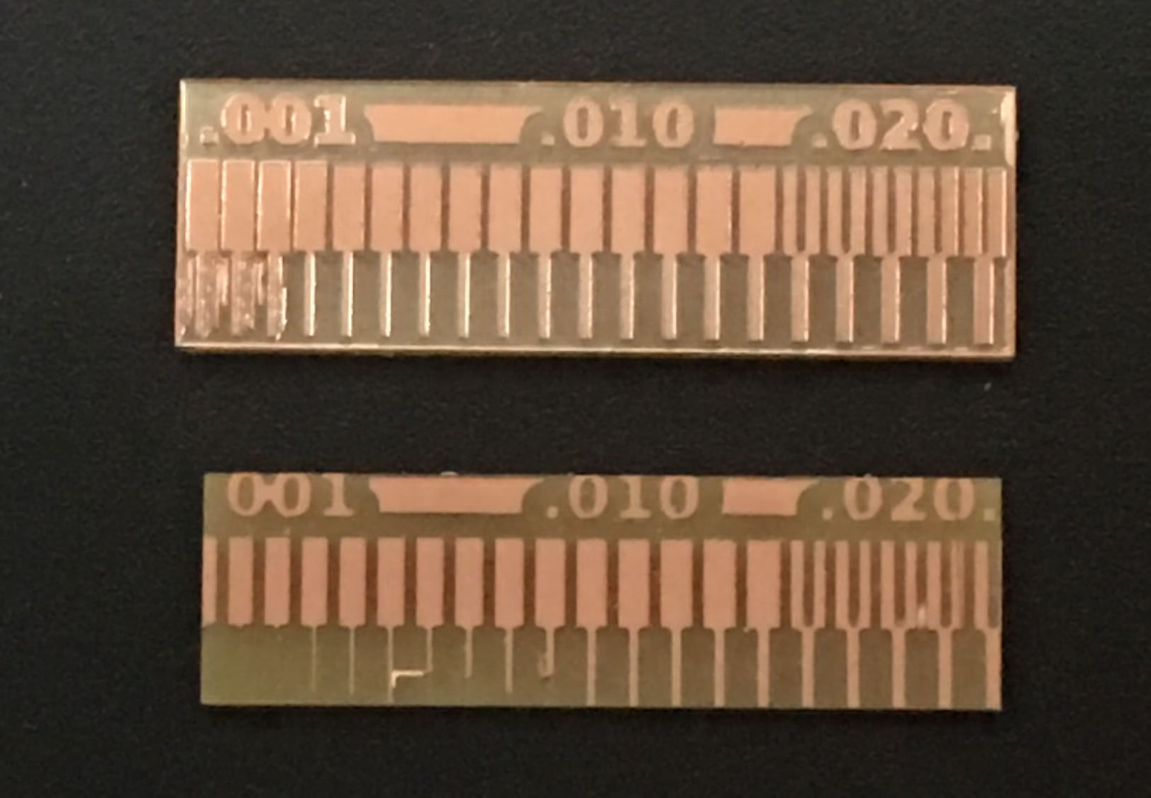
Using the same machine, bits and board;
MODS presented better results. Begin able to mill up to .005 lines when fab modules only could do .011.
So our software of choice for the rest of the process will be MODS.
Individual Assignment
The goal of this week assignment was to produce our own FapISP. The FabISP is an in-system programmer for AVR microcontrollers, actually it is an self-made USBtinyISP, which we are goinig to use for programming the microchips of our next PCBs.
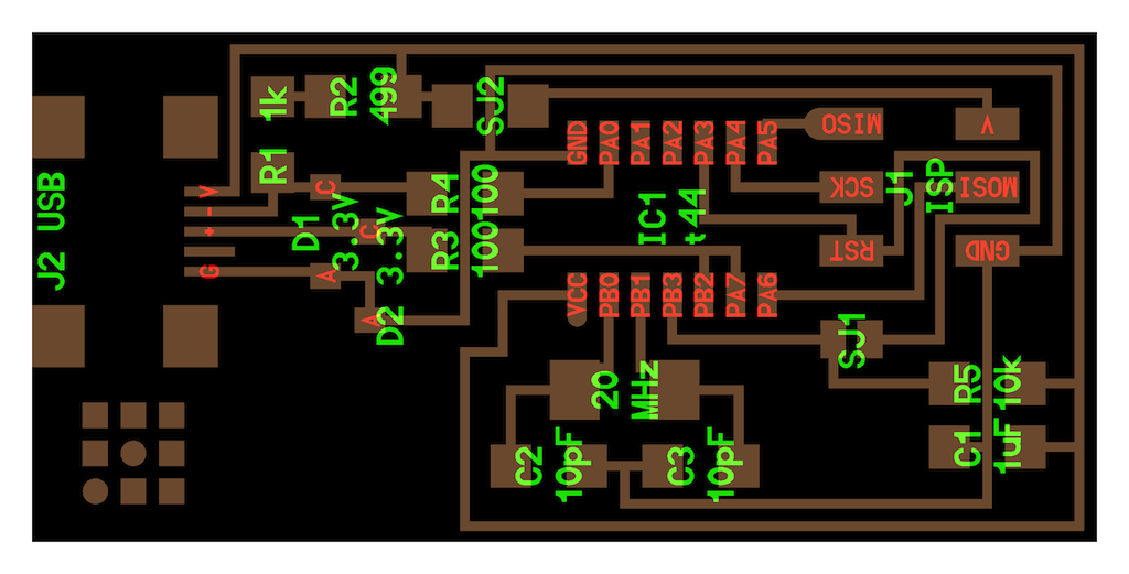
I started designing the board, modifying the PNG file of the circuit with Adobe Photoshop.
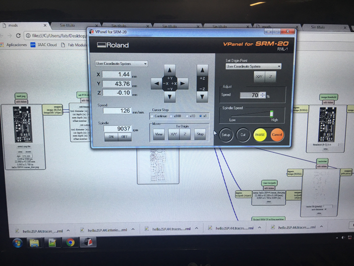
Then I had to generate the RML code. For this I opened MODS, uploaded the PNG file and entered the same values, that we have been using before in our group assignment (see setting above).
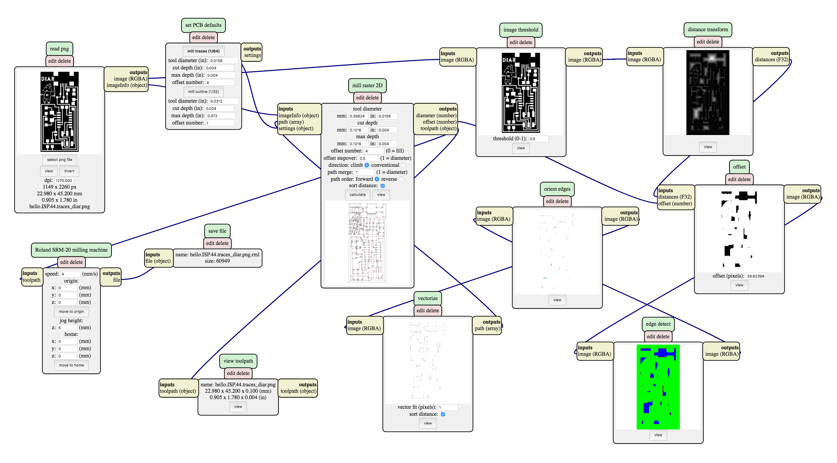
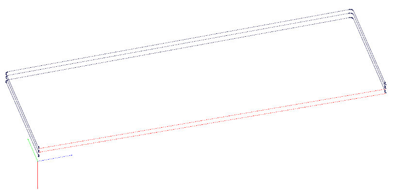
Then I let MODS calculate and save the RML code. It will open the preview of the milling traces in a new browser tab. The following picture shows the traces the outline cut.
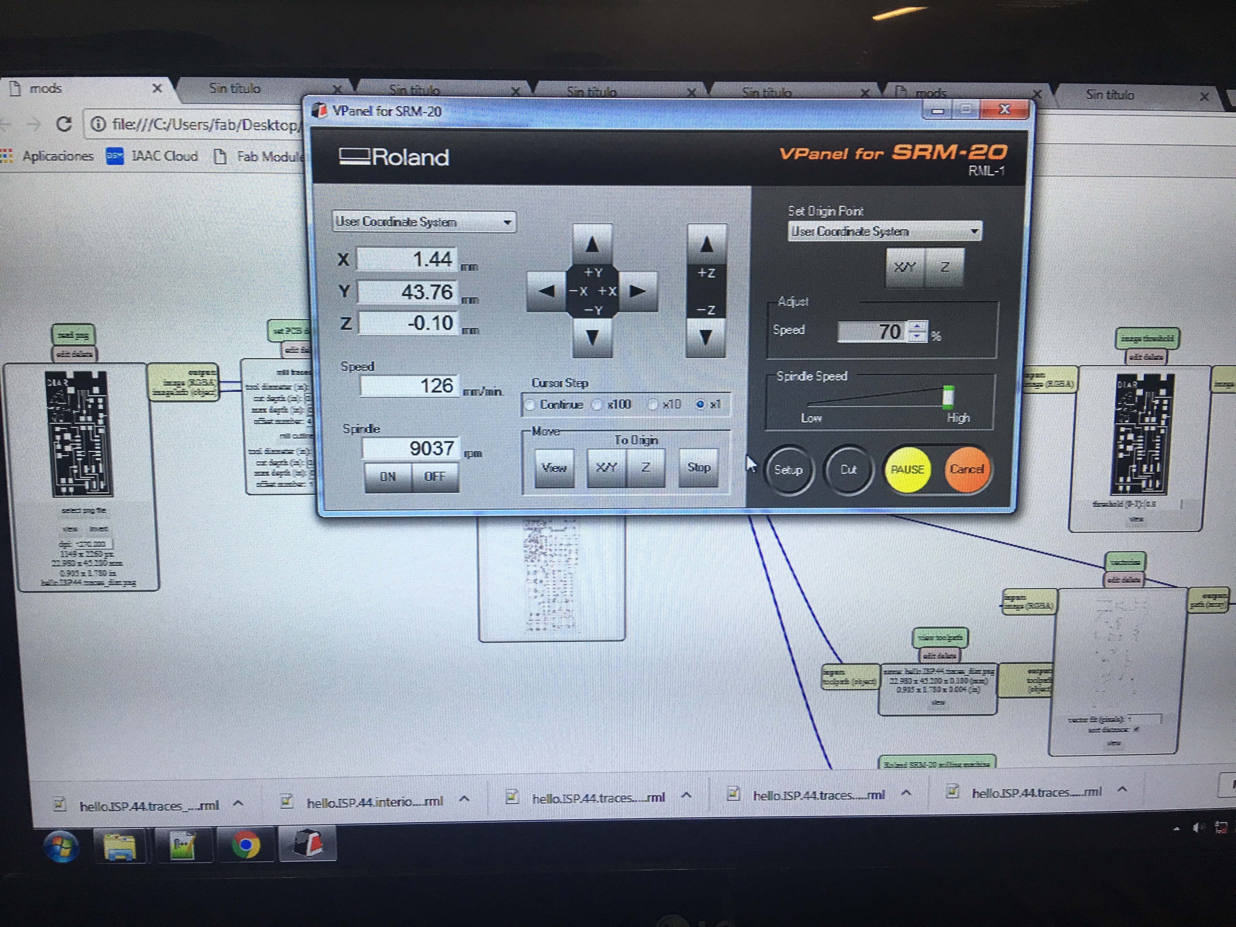
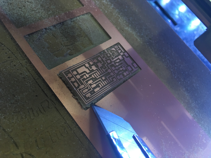
After this the design of the traces and footprints are ready to be sent to the milling machine. I had to fix the copper plate on milling plate, put the 1/64 mill and set X-, Y- and Z-axis to zero.
Ready to send it to the Roland SRM-20 machine.
The milling seemed to be successful, it looked like it had been a clean cut.
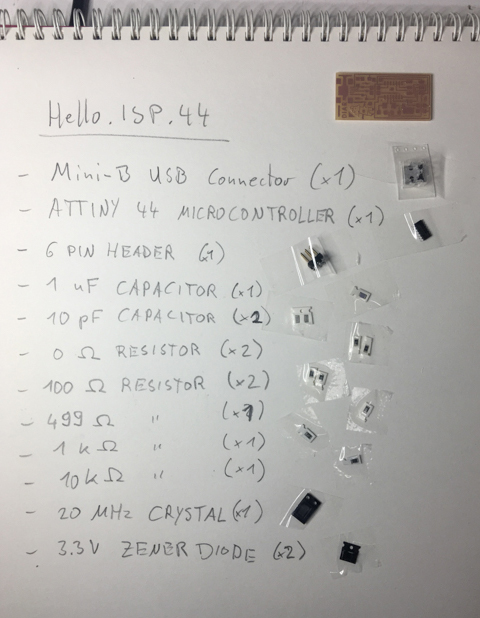
So I went over to prepare the soldering and set up the BOM (Bill of Material):
- 1x Hello.ISP.44 board
- 1x Mini-B USB connector
- 1x ATTiny 44 Microcontroller
- 1x 6 pin header
- 1x 1 uF capacitor
- 2x 10 uF capacitor (x2)
- 2x 0 Ohm resistor
- 2x 100 Ohm resistor
- 1x 499 Ohm resistor
- 1x 1 kOhm resistor
- 1x 10 kohm resistor
- 1x 20 MHz crystal
- 2x 3.3V zener diode
I made the BOM with all the components sticked to the paper sheet, which is a way to save all the tiny pieces from getting lost:
After soldering all pieces, the board was ready to be tested.
After soldering all the components, the FabISP is ready to be tested.
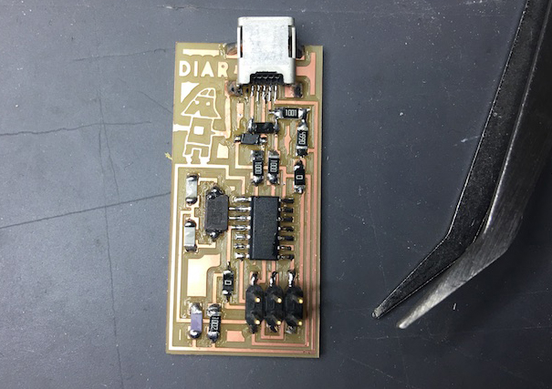
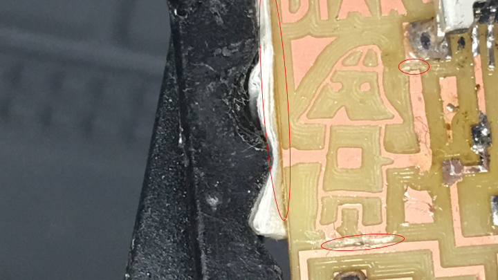
The board seemed to be working, when connect it to the USB. But then after a while I noticed, that the board was heating up slowly. This means that there was a bad circuit and I had to find it. Therefore I used a Multimeter and tested every trace on the board.
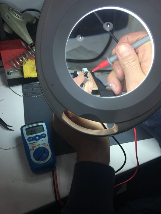
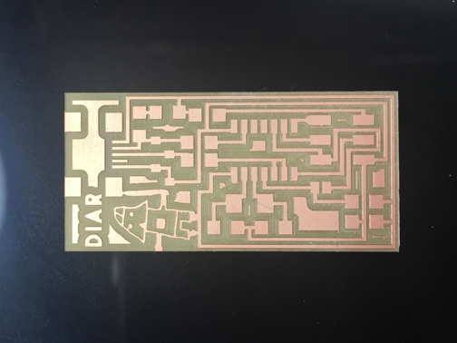
The test showed were the bad circuit was: On the edge of the board there was left a very thin line of copper, which was connected with other traces. Even in the picture you can hardly see this unwished left over of copper. I marked in red the part, which I had to remove:
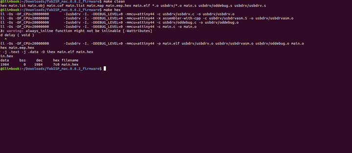
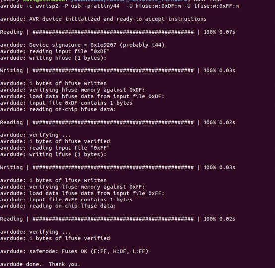
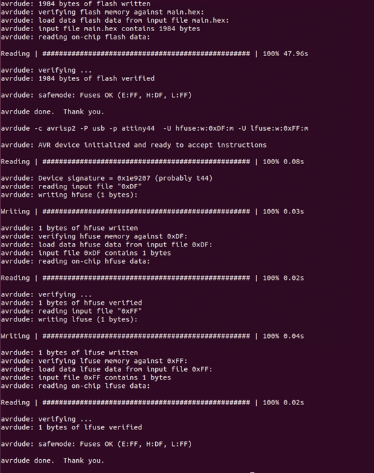
Now the board was ready to be programmed, so I download the firmware. Then, to convert the PCB into a FabISP, I had to make fuses and install the programm. The procedure here is to run the following commands in the terminal: 'make clean', 'make hex', 'make fuse' and 'make program'.
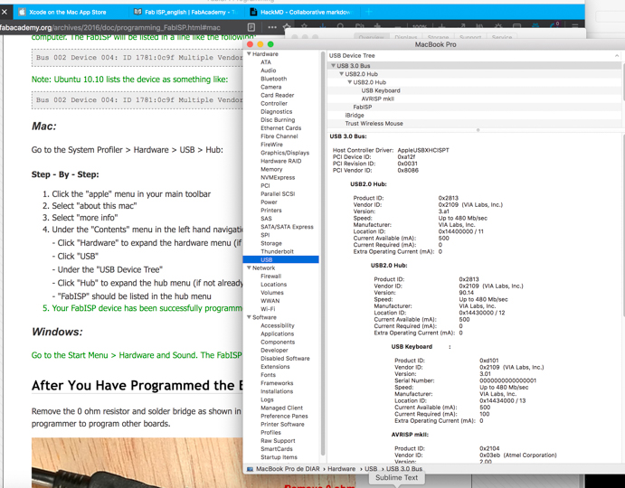
The programming finally has been made on a Linux computer, because it didn't work on my MacBook. Later I found out, that the problem was the USB-C connection, which supplies more power than the ATtiny44 accepts.
Conclusion
The FabISP has to be run via an USB slot, that provides only 1,5 A with PD.
FabISP has been finished, the assignment accomplished, now, I can use my own FabISP to programm the next PCB. Optionally the 'jumper' (0 Ohm resistor) can be removed to avoid that the programm could be overwritten in future.