8.1. Group Assignment
For the group assignment we are asked to test a computer-controlled machine to know which parameters to use as well as anlyzing the feeds and speeds.
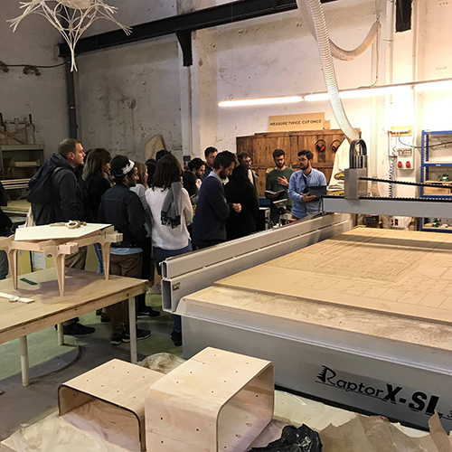
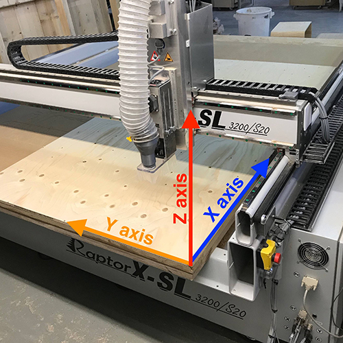
Edu, one of our instructors showed us how to use our CNC machine: Raptor X SL 3200.
Material setting
First we had to measure the dimensions of the wood board we were using, in case it would have non homogeneous thickness due to its storage or fabrication conditions.
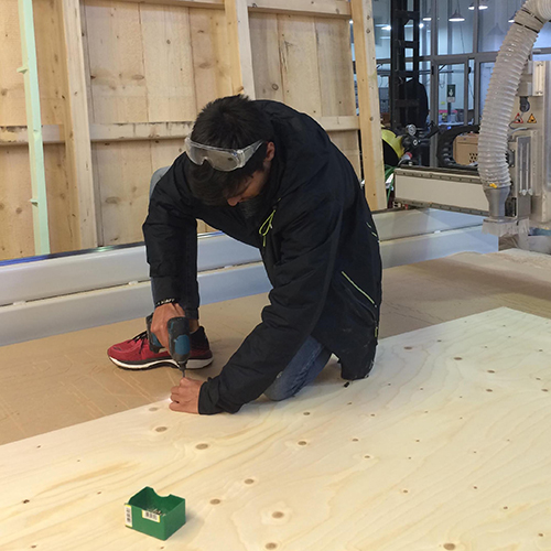
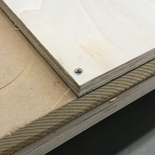
Then we need to screw it firmly to the cutting base. In all the cases a previous screw-positioning test should be made before placing the screws to confirm the mill won't touch those points along the cutting process (this will be explained later on).
Machine setting
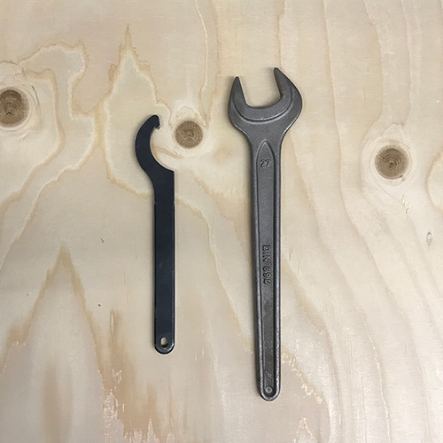
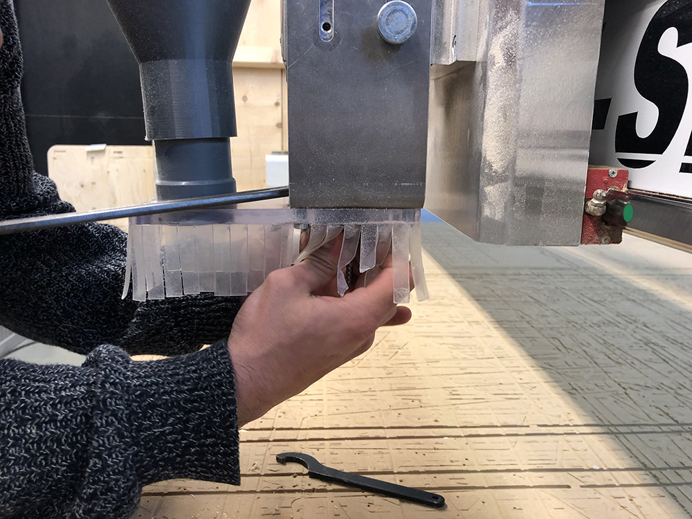
Then we need to place the tool, the end mill must be introduced into a collet that will be screwed tightly to the holder with the help of a key and a wrench. If needed, the dust collector can be removed to work more comfortably.
To remove the collet from the holder, it's easier if you press it laterally. It's important not to hold the end mill from the flutes to avoid cutting ourselves, as well as leaving a 5mm space in the shank between the holder and the upper part of the flutes.
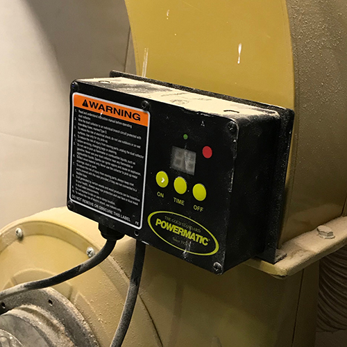
The first thing we should do is turning on the dust collector, making sure the emergency button is on, and turning on the machine. We must wear safety glasses, earmuffs and closed shoes.
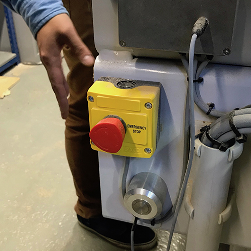
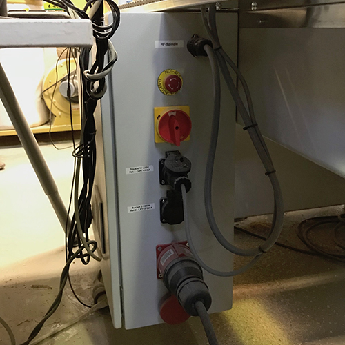
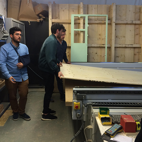
Then we need to set the axis origin. In case we align the board to the lower right corner of the cutting table, the XY 0 position will match the ones from the machine (by default it should be as the picture shows below). In other cases, we should move to the board's corner and set the origin there.
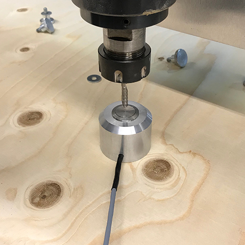
In the case of the Z position, we use an auto-leveler button. We need to place it right under the tool, put the end mill close down to the device and use the program's Z0 leveling.
Chip load calculation
Getting the appropriate feed rate for the machine is the most important thing to prevent from injuring the machine or the work. This means that the kind and quality of wood, the type of tool and the speed of the tool, are basic things we should think of before starting any work.
So, to get this feed rate we just need to multiply the spindle RPM by the number of flutes and the chip load.
Knowing we have a 2440x1220x15mm spruce plywood board, and according to the wood maker, the material's chipload is between 0.11"-0.13" (converting in mm), we made the calculations for 18k, 20k, 22k and 24k rpm:
- 18k x 1 x 0.28 = 5040
- 20k x 1 x 0.28 = 5600
- 22k x 1 x 0.28 = 6160
- 24k x 1 x 0.28 = 6720
Testing
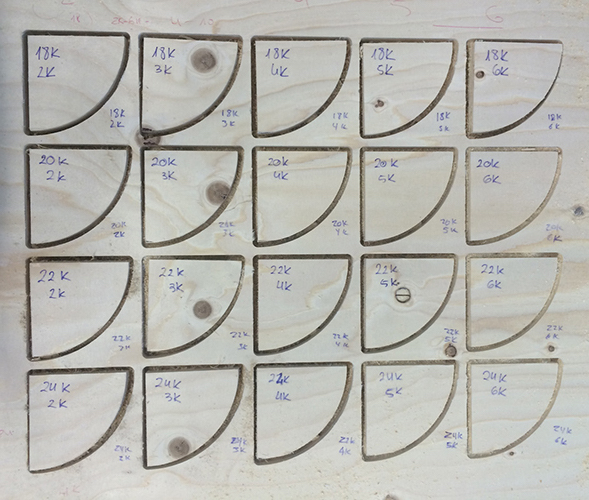
Despite having made the calculations, we made different testing combinations that went from 18k rpm and 2k feed rate, to 24k rpm and 7000 feed rate. We used a 6mm downcut end mill for the first exercise.
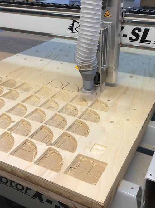
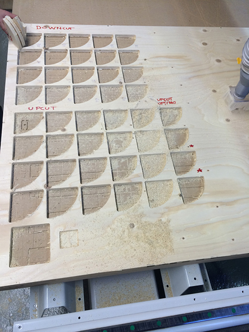
The results matched the maths. This are the final testings. The best result was made at 18000rpm and 5000mm/s.
We did the same exercise with an upcut end mill, and the results happenned to be better. We think this was because maybe the tool was newer and sharper.
8.2. Individual Assignment
For the individual assignment, that required making something 'big', I didn't want to repeat a chair exercise as I explained on CAD assignment, or use quickly a huge load of material with a single technique, I wanted to test different things.
So I'll show first a 2 element bike kit: a back basket and an anchor made of rectangular joints; then a mountain's mockup made by pocketing; and a pair of dove joints for wooden structures.
8.2.1. Bike set
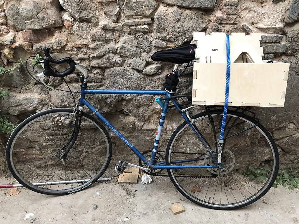
As I said the bike set is formed by 2 elements: a box that will be tied to my bike's back-tray; and an anchor that could be fixed to the ground or walls to park the bike.
BIKE BOX
The main reason that I chose to make a bike box was to remove my old broken plastic basket, and replace it with something more resistant and long lasting.
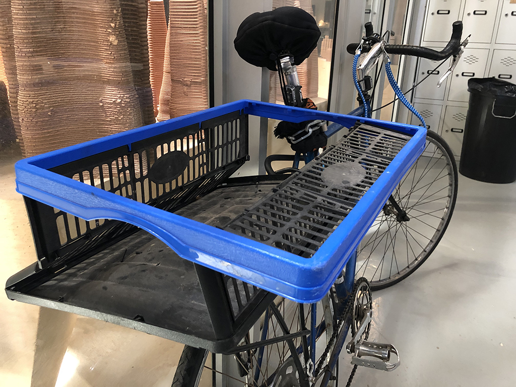
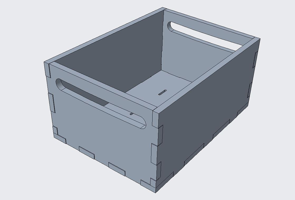
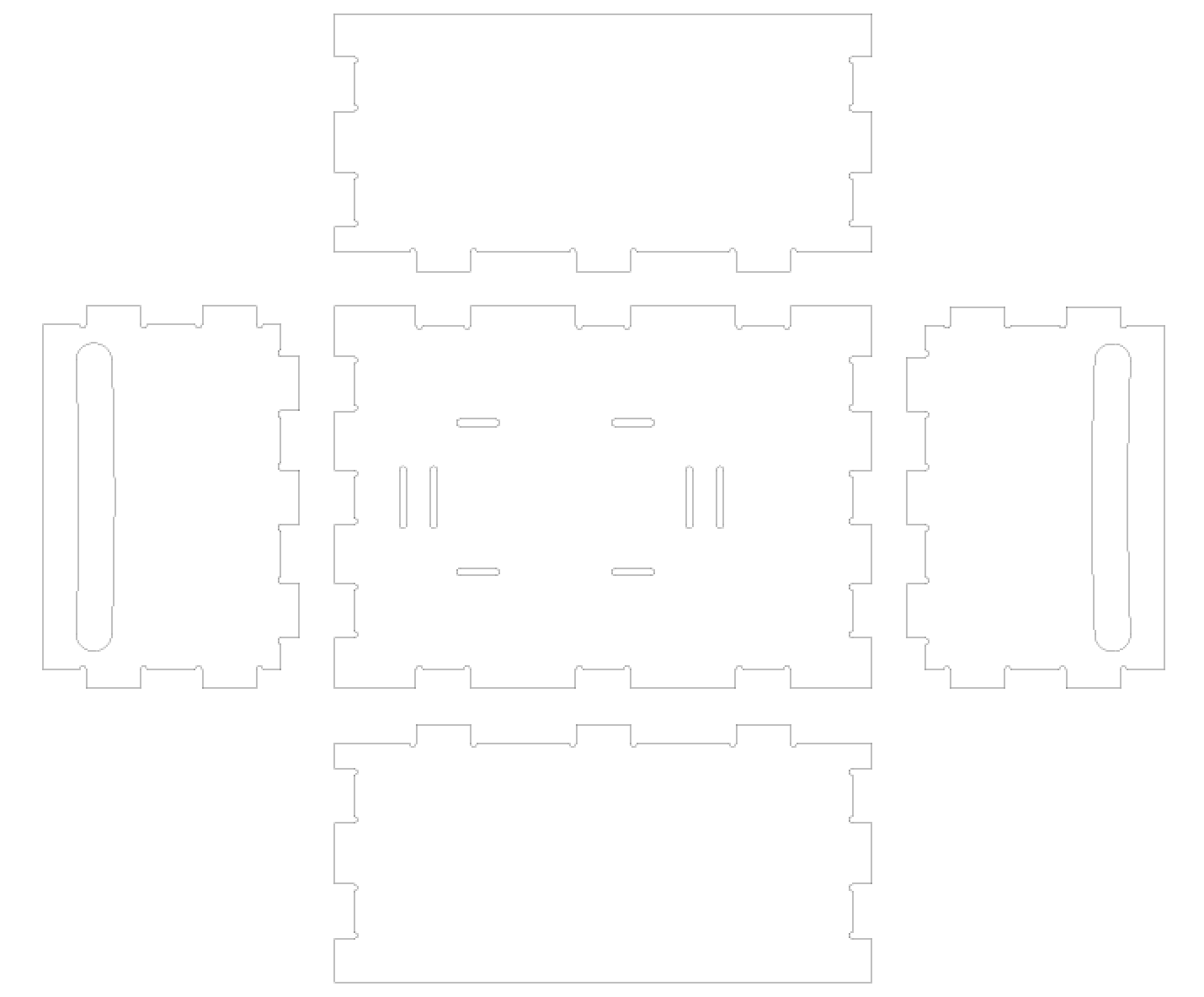
I designed a box made of 15mm spruce plywood boards (the material we were asigned). The basket will have a rectangular base with holes to tie to the bike's tray. The four walls will be attatched with rectangular joints to the base, and two of them will have a hole to grab the box comfortably.
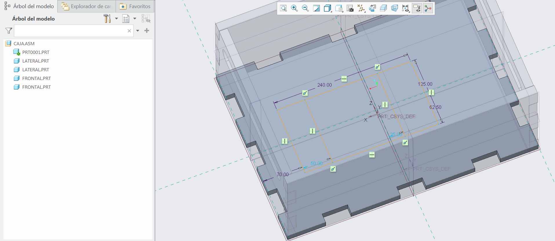
I used Creo Parametric to design first the whole basket, and see if all the joints match and the tolerances are fine.
This is how it should look all assembled.
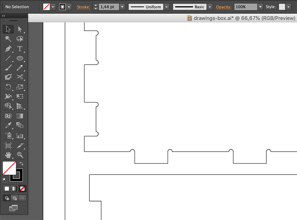
Then I got the drawings and exported them on pdf to modify the incut corners, as the round mill cannot make a straight corner, so I made some D6.1mm roundings (a bit over end mill's diameter) cutting through the corner to achive a sharp joint.
This is the final drawing of the bike's box pieces:
BIKE ANCHOR
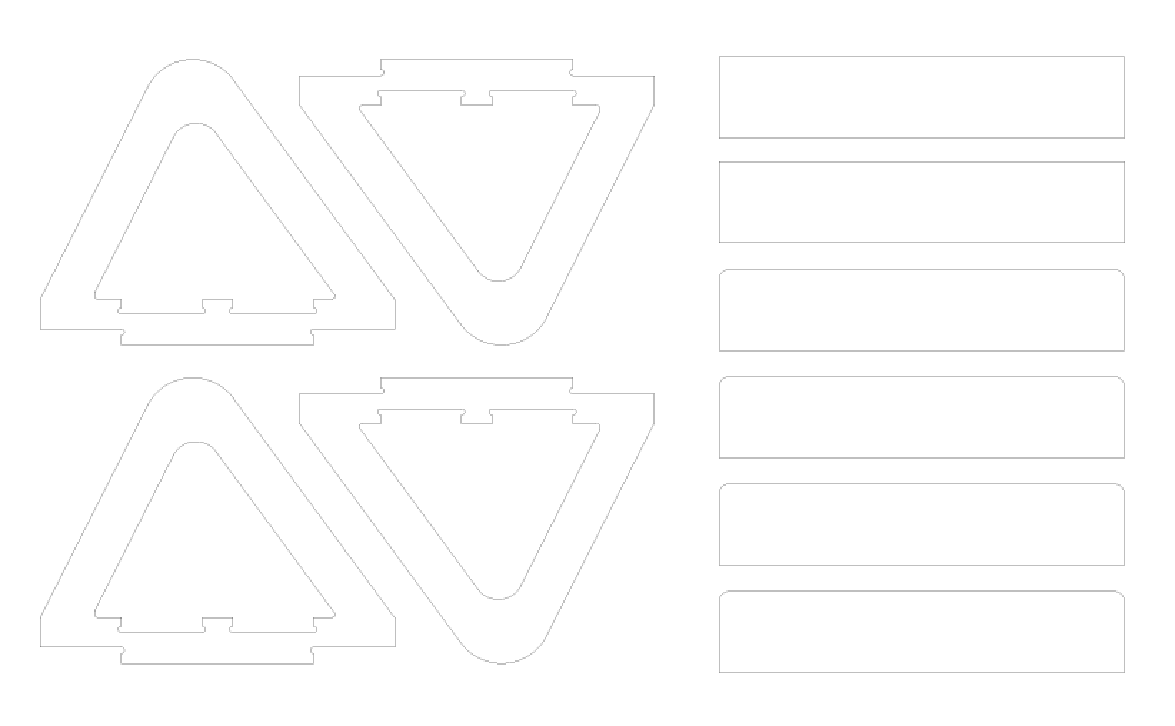
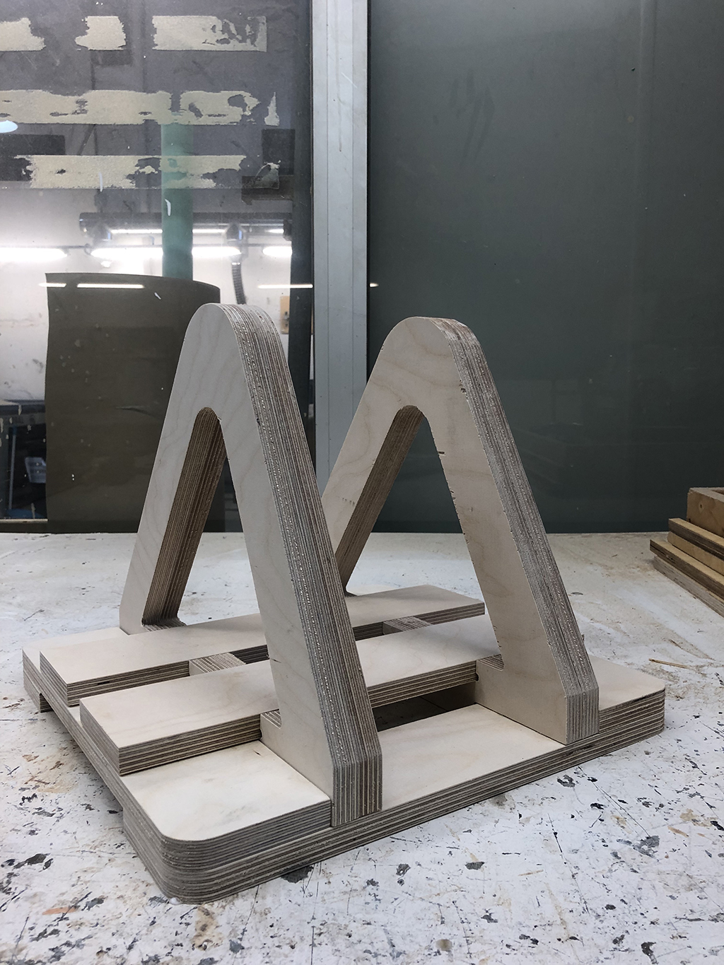
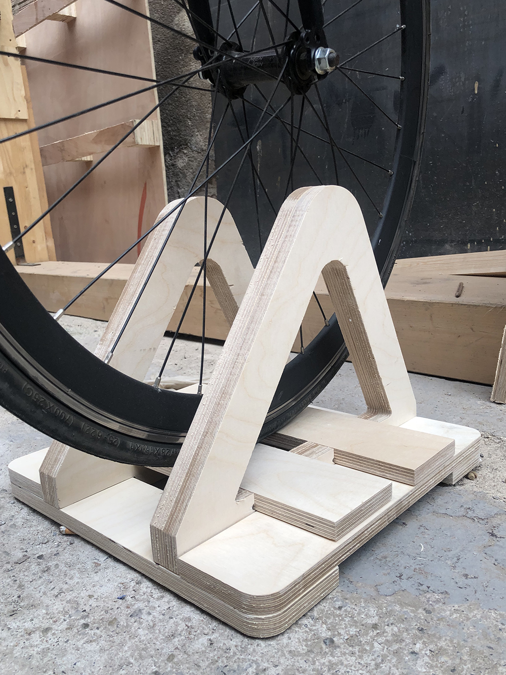
For the bike anchor, I designed a criss-crossed square to lock my bike's front wheel. So I did the same process to design this part.
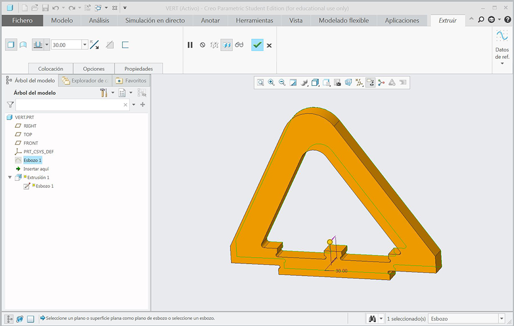
This is the complete model.
And here there is the drawing of all the components. I decided to make r2cm roundings to the square's corners later on Rhino (the four last horizontal boards on the drawing).
Cutting process
As both works are made with the same material and cutting process, I placed all the drawings on the same layout, and imported them to Rhino.
Then opening the RhinoCAM plugin, we can select in the Mill extension all the working parameters for the process. So I start defining the material's size which is set on the Box Stock, and the screws position as I mentioned before. We set a engraving work just to mark their place and limit our working area.
In case there are diferent working processes, it's very useful to give a line color for each process. In my case the process for cutting either the box or the anchor will be a profiling. So I follow setting up the material, tools, machine parameters on the Axis Profiling function. I will start with the cut parameters differing from outcuts or incuts for the piece's perimeter or inner holes, respectively.
These the cut parameters for outcuts:
And these for incuts:
As we tested on the group assignment, the best cut direction on this material is downcut.
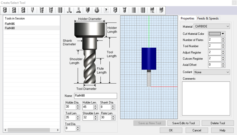
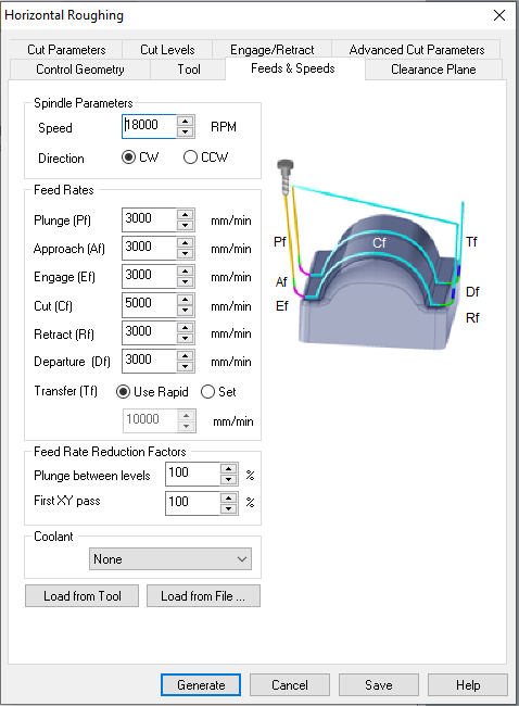
Then I create my tool. I chose the same tool we used on the group assignment, a D6mm downcut flat end mill. Taking the numbers of the chip load calculation that we made, I selected the 18000rpm and 5000mm/s parameters.

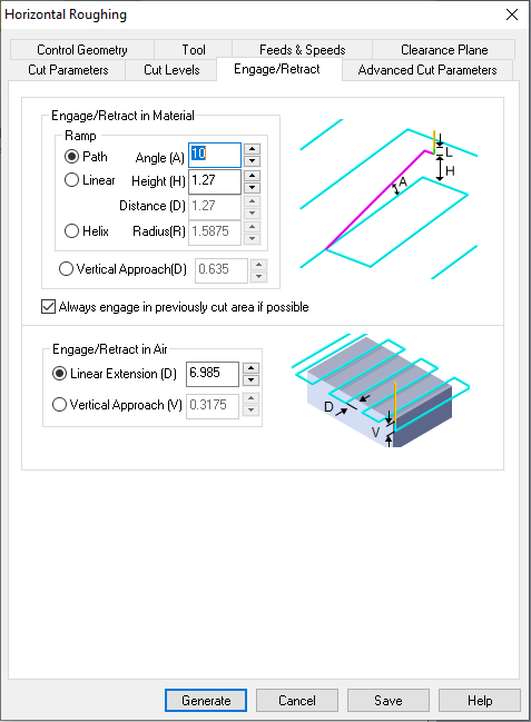
Then I moved on with the rest of the parameters: depth cut (bigger than 15mm), size and number of bridges to hold the pieces while cutting, entry and exit of the tool and feeds & speeds.

Then I generate a simulation of both processes (first the roughing for screws and then profiling for the cutting), once I see there are no failing travellings, or colapsing toolpaths, I create the NC files that will be run with the CNC software.
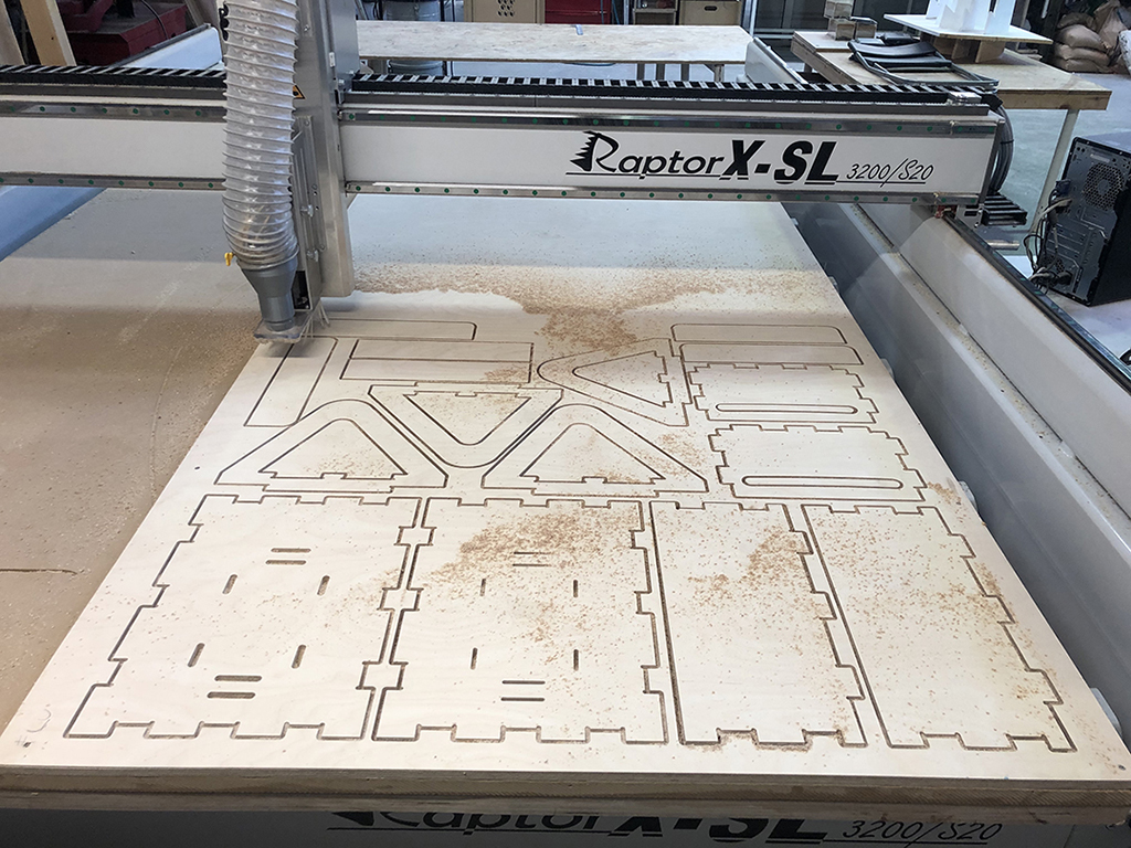
This is the cutting moment after following the steps I mentioned previously.
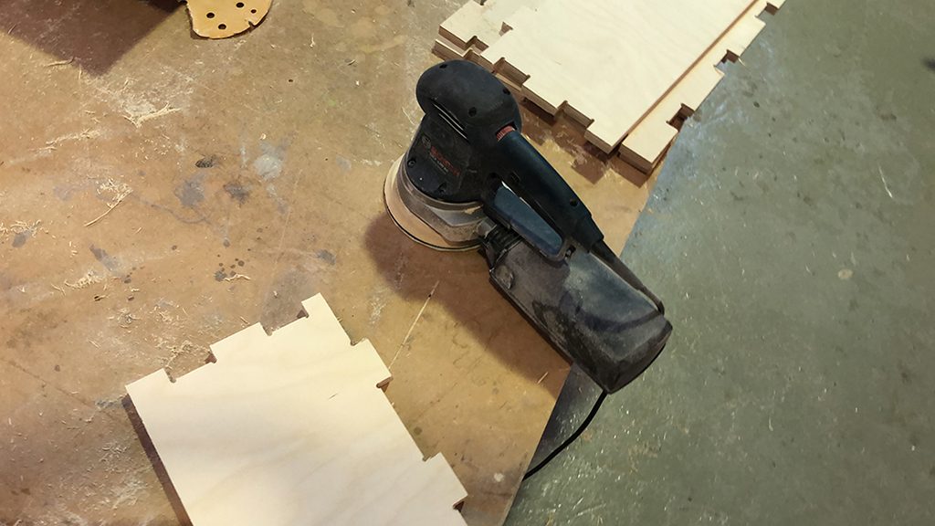
Then a bit of postprocessing, I need to sand the edges to make it fit just pressed. Although I set a 0.5mm tolerance on the design, after the cutting process a bit of sanding is needed.
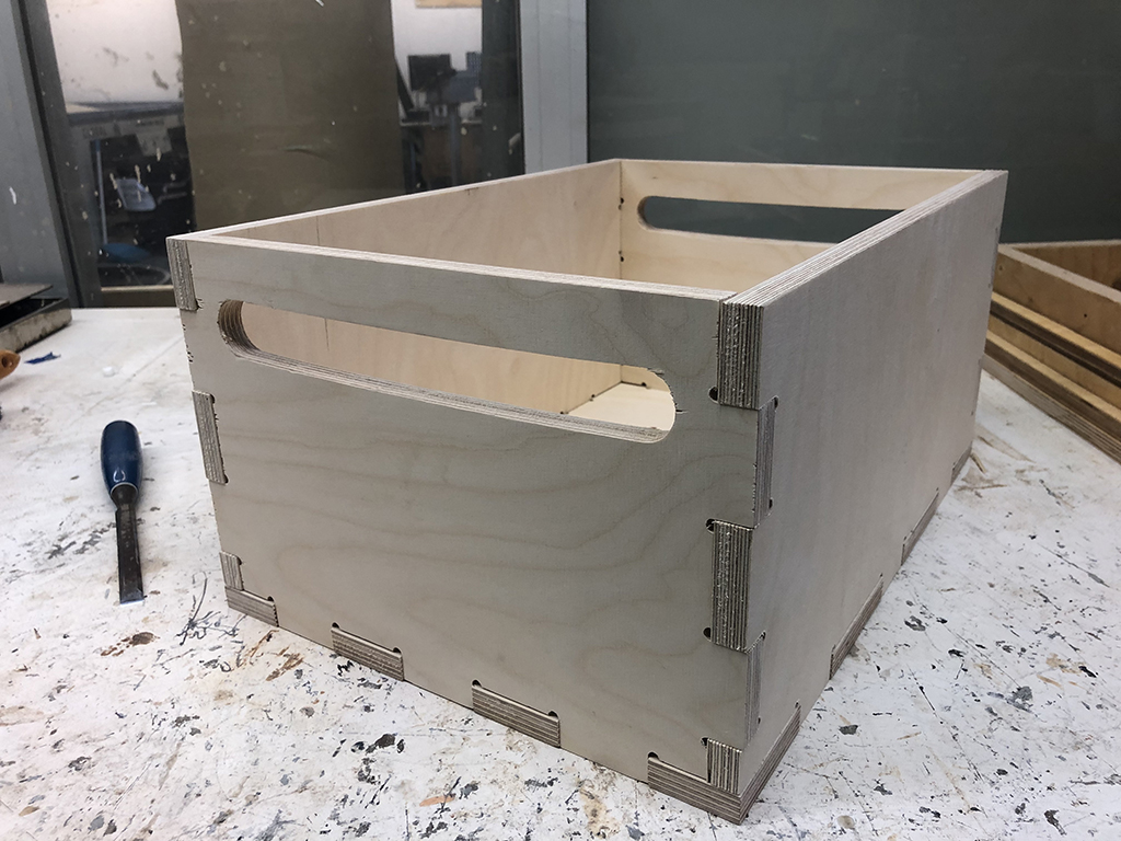
And this is the final result of both pieces:

Then all assembled looked fine!
8.2.2. Mt. Gorbea mockup
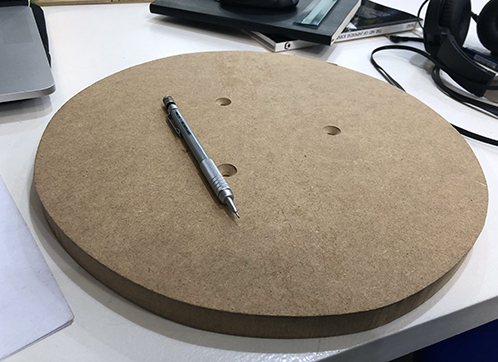
For the individual assignment I decided to modify an old piece of MDF I had around, by substracting by layers. The idea is to represent the topographic layers of a mythological mountain in my region called Gorbea by making surrounding pocketings on the wood that will grow 1mm per layer from the top to the bottom.
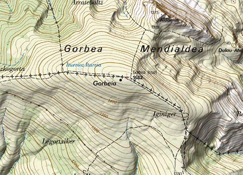
Once I got a topographic map of the mountain, I outlined the drawing with vectorial lines in Illustrator and saved it as a pdf file, that I will import later on Rhino.
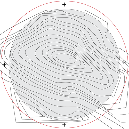

In RhinoCAM again, I set the process parameters. I will need to make 5 different processes:
- Engraving: for the screws position
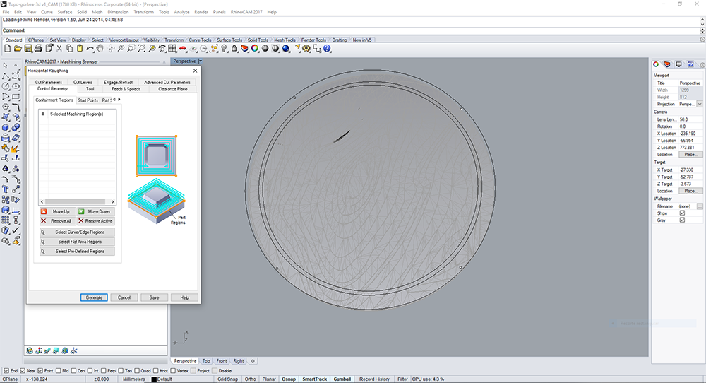
- Horizontal roughing: to remove most of the material
- Horizontal finishing: to give nice finishing to the surface
- Clear flat tops:
- Profiling: to make the outcut of the piece
In this case I am using a D8mm flat end mill for all the processes. As I couldn't find the wood's chipload info, I was advice to use similar feeds & speeds (spoiler: it worked perfectly).
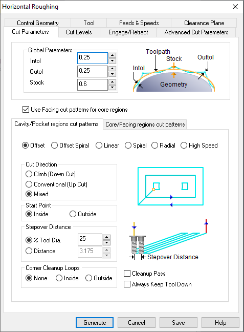
These are the horizontal roughing parameters:
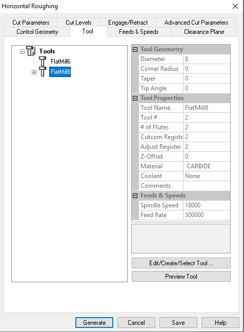
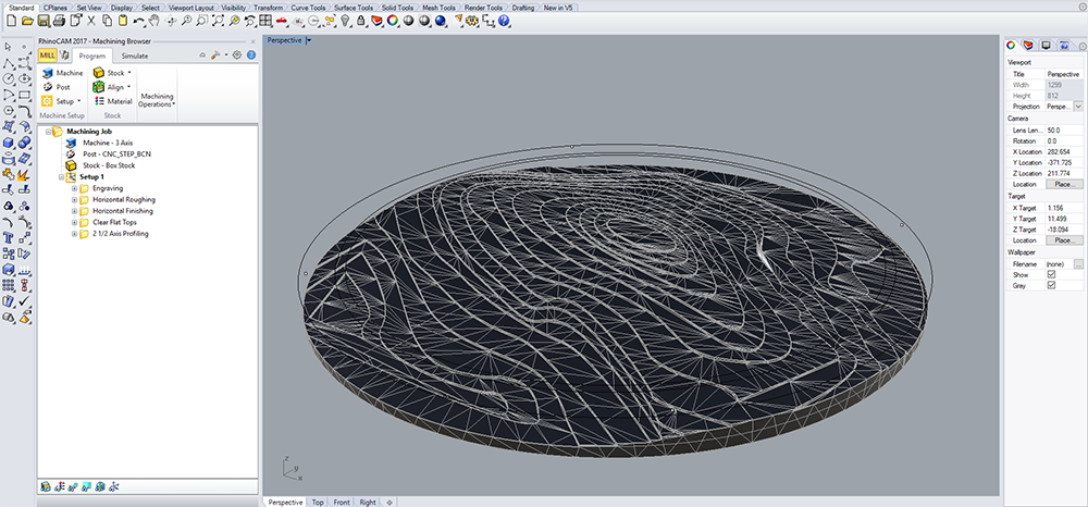
This is the mesh generated by the software:
Then I tested the workflow of the 5 processes in line.
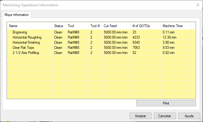
These are the 5 processes especs:
Process
Then I imported the nc file to the Kinectic software (CNC's program), and after repeating the same process, I started with the cutting process:
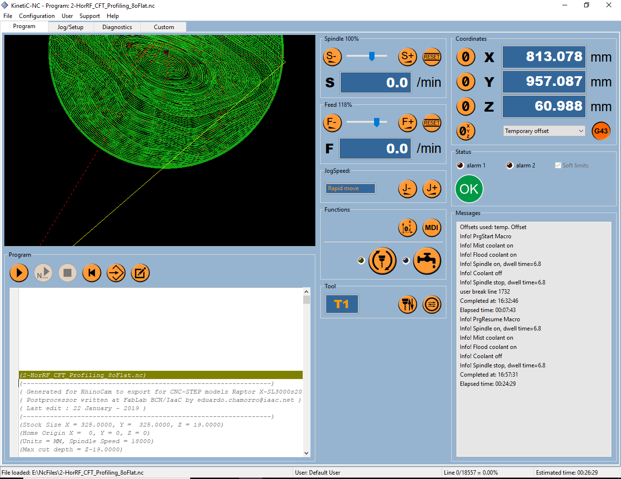
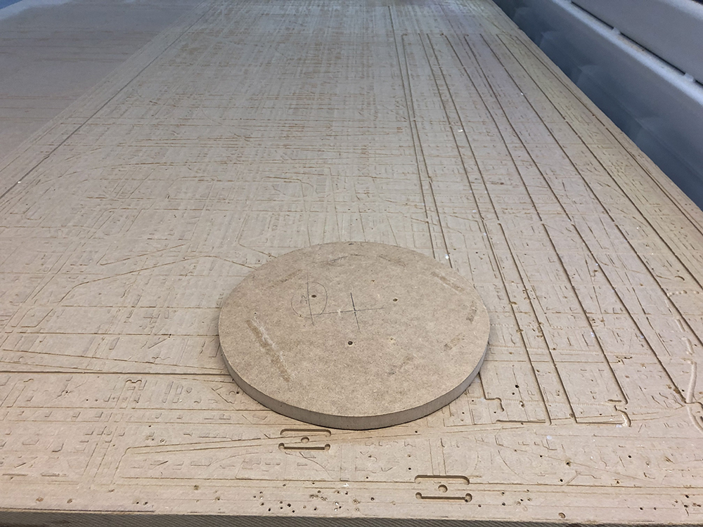
As it was such a small piece of wood, and for being round I had no axis reference of its position, before doing the roughing for the screws positioning, I screwed manually the piece in the middle to keep it fixed during the first process, then I removed the first screws.
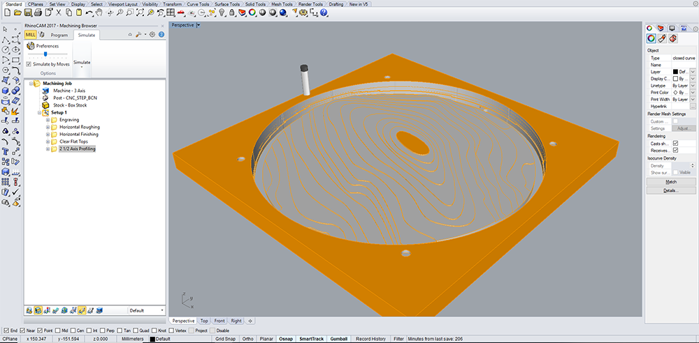
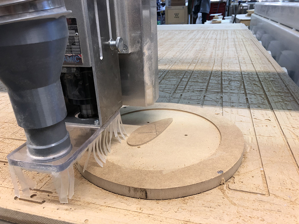
Here you can see the pocketing process. As the margin from the model to the edge of the piece of wood was too narrow, I had to screw the piece from the sides not to enter into the cutting area.
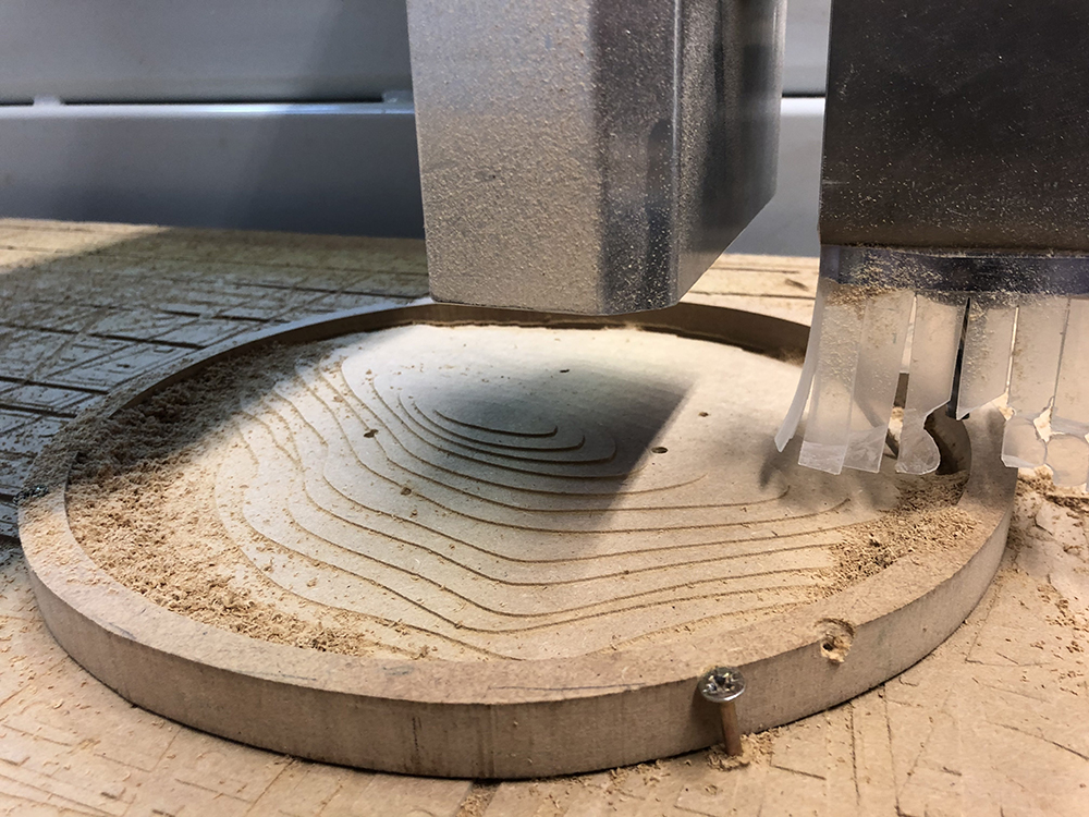
And this is the final result of my Mt. Gorbea mockup.

8.2.3. Wooden joints (extra future project)
As an alternative, I want also to try traditional japanese joints to make a structure for my hammock, made of plywood pieces. These are some refs:
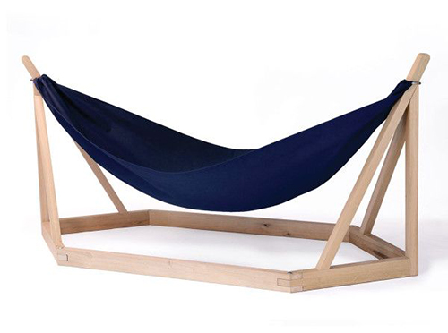
I chose these types of joints:
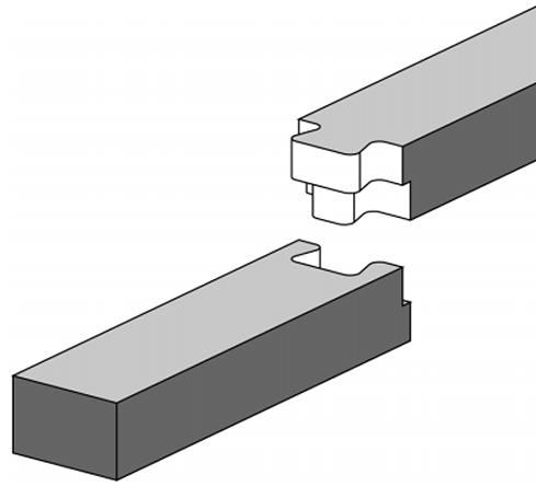
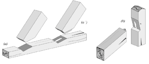
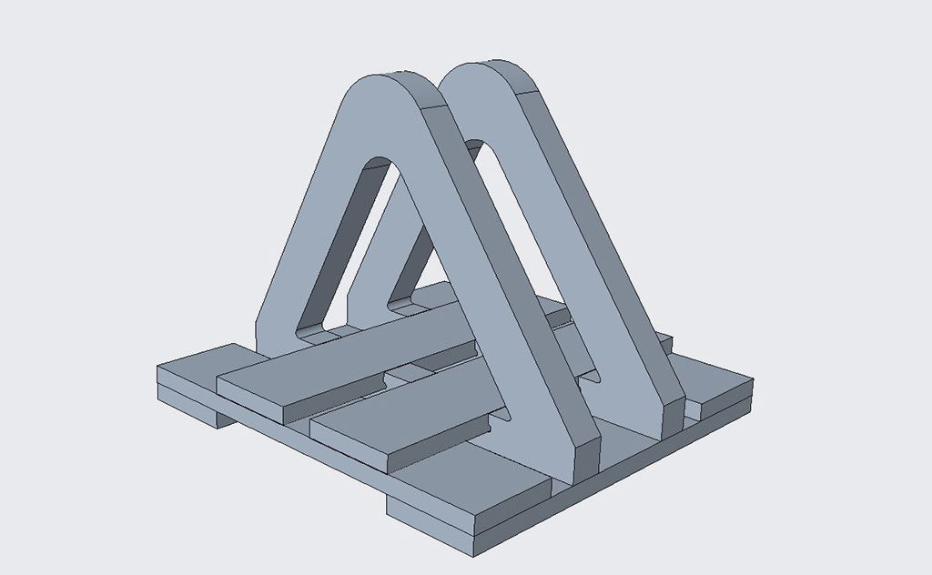
I wanted to try a horizontal joint for the base, and a tilted joint for the holding poles with a 60 degree inclination from the base. As the joints will be made out of 3 layers of 15mm plywood, I will display all them on the same board and cut them independently.
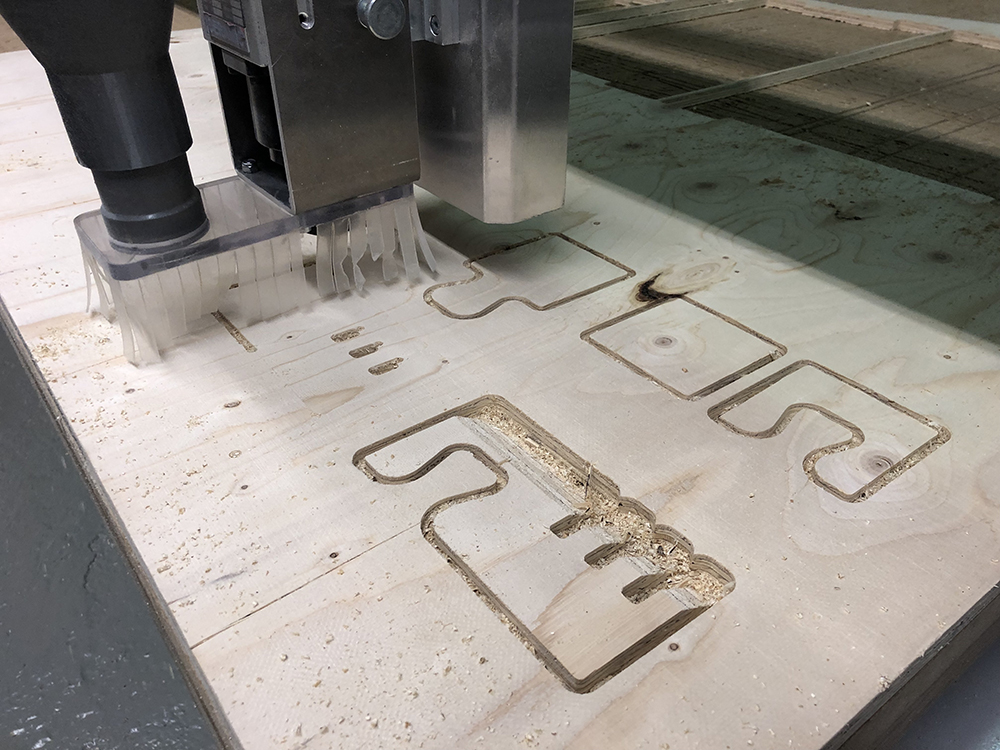
Missing CAM files, but the process was similar to the previous one, as I cut from the top layer to the bottom, sometimes with some slope, that's why it is called a 2.5D cutting. This is the cutting process:
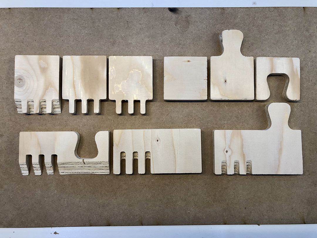
This was the result of the cutting:
And the assembled joints:
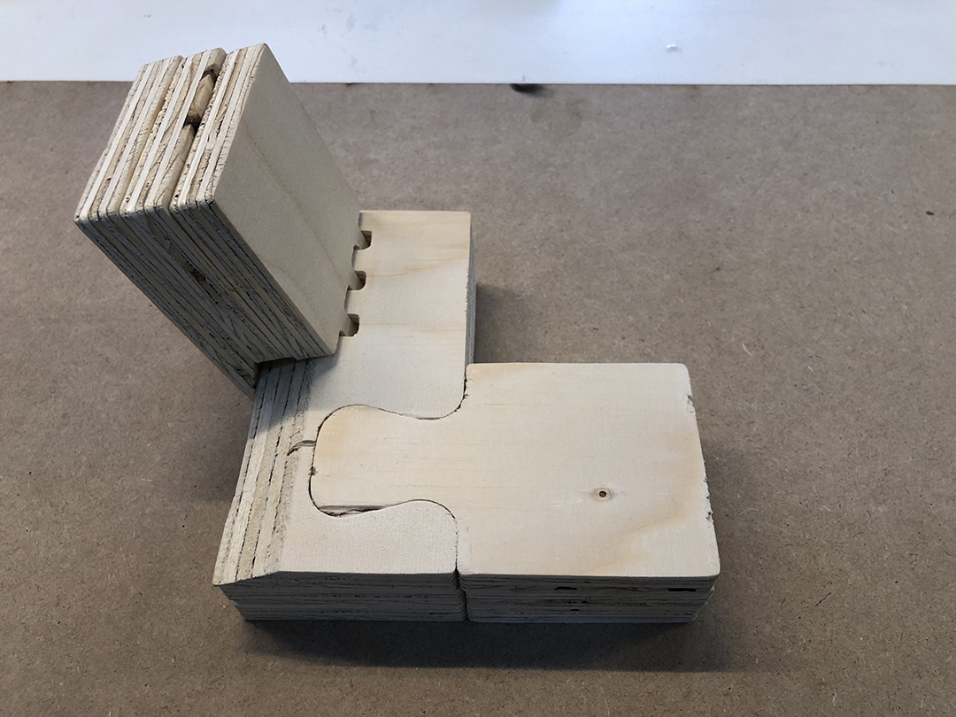
The 0.5mm tolerance for the horitzontal joint was successful, but for the tilted one a 1mm will work better, specially not to stay for a long time polishing the parts.
Moreover, the tilted ones should have a redesign to gain more joint surface and remain stable as a whole structure without extra screws.
