Overview
The bike tracker consists of a charging circuit to regulate the dynamo voltage and simultaneously charge the battery and power the circuit while riding. This power is given to a microcontroller which talks to the GSM and the GPS module.
Planning
GSM module
First of all I needed to plan all the electronics to order something. I spent way too much time on the research for a mobile communications module, because I wanted to fit everything into the bike frame, so the module must be really small. I didn't find anything small enough, so I just settled to use the Sim800C module. It is quite small, especially it does have a really small antenna. Which was surprisingly even indoor able to get a signal. With this I also bought a new SIM to use in the module.
The Sim800C module
GPS module
The search for the GPS module then was much easier, as I did know that I wouldn't be able to fit the tracker into the frame. But I decided to go with the smallest I found, which was the Adafruit Ultimate GPS module. This is an incredibly small chip and antenna, everything integrated to the size of the antenna. Which itself is very small for a GPS antenna. Unfortunately Mouser didn't stock this item so I needed to go with the same module already on a small breakout board. But the module without the breakout board would definitely fit into the bike frame, which is very good.
The GPS module
Charging Circuit
Now we come to the charging circuit. I searched a lot for articles on the topic of charging a battery from the dynamo. And there were quite a lot of tutorials, but not of them really good and much explanatory. Two tutorials which helped me the most are this one on charging a li-ion battery from a dynamo and this one on how to switch the voltage from the dynamo to battery when the bike is stopped. Below you can see the schematics and board design of the charging board. First of all there is the connector. The next part is the bridge rectifier (DF04S) to get dc current from the ac current the dynamo creates. After this there are two buffer capacitors, a big one with 2200uF to supply the rest of the circuit with current when the bike is stopped shortly. The second one is to smooth high oscillations the input voltage. The next small block is the voltage converter (LDL1117) for 5V, because the dynamo can output 1-12V, which the charging IC does not like. After this the charging IC (MCP73833) comes, which looks huge in the schematics but is actually the smallest part of all. This IC can charge a one cell lithium ion battery with a current of up to 1A. The next thing is the battery connector (J2). Over the battery connector you can find the mosfet and diode, which make the circuit to change from 5V to the battery voltage when the dynamo is stopped and so the 5V voltage drops to zero. The last chip is again a voltage regulator for 3.7V, so that the tracking circuit can be supplied with the correct voltage.
The schematic
The board design
Dynamo
I also needed to get a new wheel with a dynamo, because none of my current bikes have one.
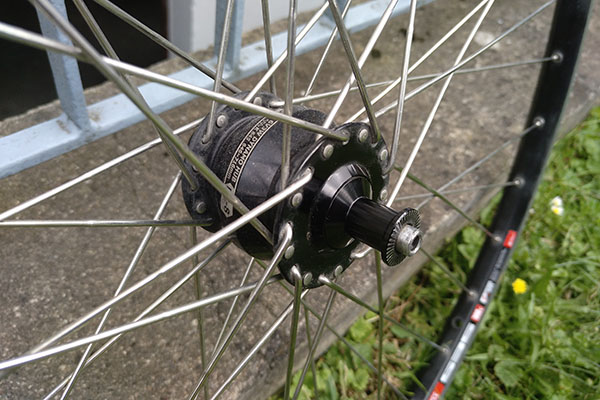
New wheel with dynamo
Making
Boards
We got a new PCB mill (LPKF ProtoMat S104) in our lab and it was a hell of work to get it running. The biggest problem here is the software, which is definitely more intuitive than the previous one but crashes randomly. After several hours it seems like one problem is executing the software with the integrated Intel graphics card, the nvidia in my laptop works much better. But still, I had one design which didn't work until I did some random changes to the Eagle file and exported it again. Another point is that the mill feels much slower than the previous one, because it takes much more time for warming up the motor, changing milling heads, adjusting them, starting the software and so on. Also after cutting a few boards from one sheet, the sheet was suddenly warped and the resulting cut was quite bad. But enough of that. It also has some amazing features, like automatically adjusting the milling head with a test cut to the real width it was cutting. It does a test cut, then looks with the camera how big it really is and adjusts for that.
First board I produced was the charging board:
The parts for the board
Solder paste applied
The finished board
After trying to solder an XMega32A4 but connecting the majority of the pins and not being able to fix this I decided to go with another chip. So I produced the board with an ATMega328, which we had in the lab so it unfortunately is no SMD chip, but easier to solder.
The failed xmega board
The atmega board
Case
For creating the case I first tried to match the curvature of my bike frame, so that the box would sit better on the top tube. Therefore I measured the frame and created a curvature, which I redesigned several times to match the frame better:
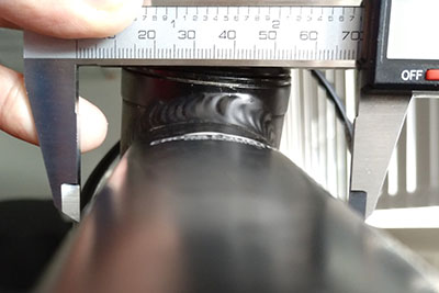
Measuring the frame
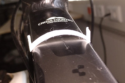
First test
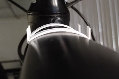
Redefined tests
After I found the curvature I did design the case in Fusion, with holes to fix it to the bike frame, a hole for the dynamo cables to go in and with a cap on top.

The design in Fusion
The printed case worked out to be fitting perfectly and I didn't need to reprint the whole case.
The printed case
PCB frame
As we can only produce PCB boards with open connections it is important to protect them from being shortened, especially when other conducting stuff is around. So I decided to cut a frame from plexiglass to fix the boards together with screws.
The cut frame
The boards put together
Programming
Testing modules on its own
I started by testing the GPS and GSM module at its own in the beginning to see that both worked properly on its own. The GSM module gave me headaches, because I put the SIM in the wrong way and searched the error elsewhere. It took some time to realize what I did wrong. I just didn't see a very tiny pictogram, where it is also hard to see the right direction. I was just assuming that the SIM goes in with the corner cut away first.
The GSM module at the window for better connection
The right direction of the SIM
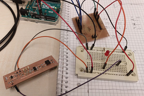
Then I was testing the atmega at the power of my charging board and the gps module. The gps module worked great, you just needed to be at the window and wait some time until it had the position fixed. The atmega had some strange problems with not being programmable and then being programmable by following the same procedure over and over again.
The cut frame
The boards put together
Bringing everything together
Then I could bring everything together. The software I wrote is linked on the bottom of the page, I will shortly describe the function here. I used the Adafruit GPS library and also the Adafruit Fona library, as they use a similar SimCom module in their board and the AT commands are the same between a lot of different devices. I am starting both devices and communicate with them via the UART interface. Then I wait until the gsm module tells me that there did an SMS arrive, ask the GPS module for the current position and send it back to the sender of the SMS.
Testing / Evaluation
The first test I did was testing the charging board with a multimeter, connected battery and somebody turning the wheel. Everywhere the expected voltages where present, so everything worked great. This is also shown in the video at the bottom of the page.
Everything integrated into the box
Another thing I tested was the main function when everything was mounted on the bike by sending an SMS and receiving the position back. This is also shown in the Video.
Video
I showcased a lot of production and testing of parts in my video in short clips and therefore also made fewer pictures of the whole process. So in the video is a lot of the manufacturing and testing shown:
Files
Here you can download the files created during this week:
The Eagle project and gerber files for the ATMega328 board
The Eagle project and gerber files for the charging board
The case design file (Fusion)
The case stl file
The stencil for the charging board to lasercut
The board separator file to lasercut
The program on the ATMega328
