Exercise 03. Computer Aided Design
Situation
After the lesson about different 2D, 3D, simulations, ecc. on Wednesday 31 January, the assignment for this week was to use some of these tools to model a possible Final Project.
Therefore, first thing I did has been visualizing my final project concept more in detail. I develop my first sketches and the first thing I did was to make all these schemes in ILLUSTRATOR.
After deciding how the main part of my project has to be: Custom sizing, flexible and easy to install, I took the scheme and inform myself about parametric designs in SOLIDWORKS. And when I was reading about parametrics, I discovered also the Metal Sheet module. It will help me designing flat parts which will be folded in 3D after, the Ikea concept.
The third software I used has been RHINOCEROS. Combining it with SolidWorks I am able to add a PARAMETRIC KERF to my designs, and probe the better one to fold/unfold the structure and pot-supports.
You can see below the different things I did in these softwares. If you want to see these in detail, go to Project Development area. :)
2D Illustrator Model
I did the first scheme in Illustrator, I know something about this software because I thing it will give me the most complete options to develop it. I have used some predetermined designs in .eps from some web sites like Freepik and Vecteezy, but it has been a good change to practice with the Pen tool. I practice a little bit with Bezier Method before doing it and I learned some more option of this tool.
Adobe Illustrator is a vector graphics editor developed and marketed by Adobe Systems. The latest version, Illustrator CC 2018, is the 22nd generation in the product line. But I used Illustrator CS6 due to our university license.


You can see the complete schemes in Idea Development and definition. And to see the complete files click here.
3D SolidWorks Model
SolidWorks is a solid modeling computer-aided design (CAD) and computer-aided engineering (CAE) computer program that runs on Microsoft Windows. I have worked also in SolidEdge, NX or Catia softwares during my engineer career, but I thing SolidWorks is the best and the most intuitive tool to Industrial Designers like me.
Although I have been working with the 3D modeling main module in this software, I have a lot of things like parametrization or Sheet Metal adds I want to use and I have never time to do. It is a good chance to do it know, I think. :)
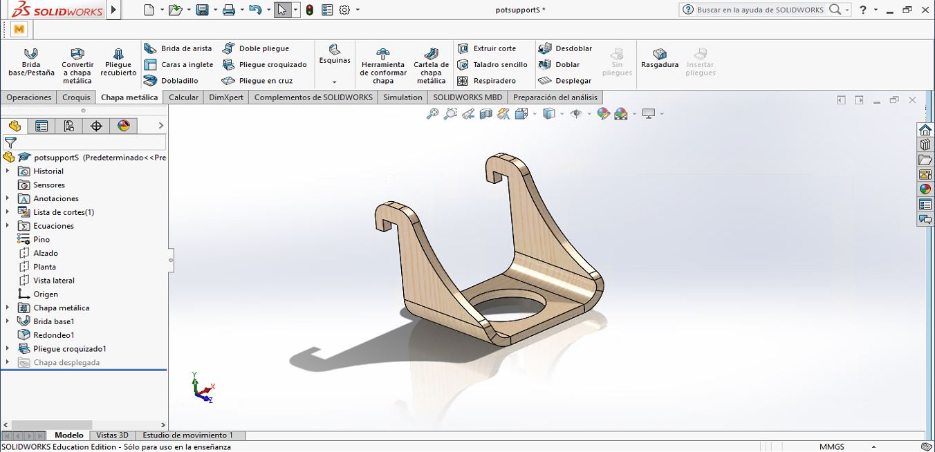
I have activated the Sheet-metal (Chapa Metalica) option in SW, as I need to create flat and foldable/unfoldable designs for my Smart Urban Garden Structure and Pot-supports designs. Although it is created to work with metal sheets, it will give me the option to see how my flat parts will be folded after being flat manufactured.
The first part I have designed in 3D has been the Pot-Support, in three sizes. The custom will have the option to get the amount he/she wants of each size. He/She gets the pot-support unfolded, and the action he/she will do will be to fold it and to mount it in the main structure.

The model of one of the pot-supports can be rotated and zoomed with the mouse/trackpad. You can set it up with:
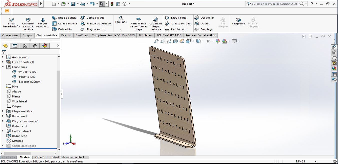
With the main Structure file I did the shame, I used the Sheet-metal option in Solidworks.
But in this part the parametrized skills were the high and width of the structure, which will be selected by the custom. The holes array, where the Pot-supports will be mounted later, is connected directly to those parametric variables, so they will be always throw all the surface.


The model of the assembly can be rotated and zoomed with the mouse/trackpad. You can set it up with:
I prepared the 2D for the three pot-supports and the structure in 2D, in the unfolded version, to export them to RHINOCEROS:
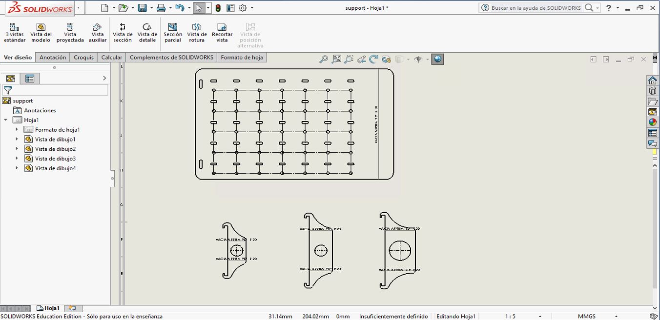
To see the complete files click here.
2D Rhino Model
Rhinoceros is primarily a free form surface modeler that utilizes the NURBS mathematical model. Rhinoceros' application architecture and open SDK makes it modular and enables the user to customize the interface and create custom commands and menus. There are dozens of plug-ins available from both McNeel and other software companies that complement and expand Rhinoceros' capabilities in specific fields like rendering and animation, architecture, marine, jewelry, engineering, prototyping, and others. Another one in Grasshoper, which can be used to make parametric files in this software.
But I have parametrized my files in SolidWorks, so I am going to use Rhinoceros only to take the 2D vectors from SW (in .dxf) and add the best parametric kerf to them.

I found this 2D file with 9 different Parametric Kerf templates I would like to make in the Laser Cut Machine next week, to decide which of them would be the best way for the structure and pot-supports:

To see the complete files click here.
InkScape
Inkscape is an open-source vector graphics editor similar to Adobe Illustrator, Corel Draw, Freehand, or Xara X. What sets Inkscape apart is its use of Scalable Vector Graphics (SVG), an open XML-based W3C standard, as the native format.
I found a Living Hinge Creator extension and I thought it interesting. I have 9 templates to Parametric Kerf, but with this extension I would be able to create a personal one, and I have never used Inkscape, so I install Inkscape in my computer and I added the extension. Once I have experimented with the other 9 templates and saw the best tipe of hinge, I will prove with it.

It is very basic, it creates Living Hinges with only a template, but I would like to probe creating something different.

I have done a test with it, but it has only one livinge hinge pattern. I discarded it, since I wanted to try different ways. Even so, you can find one of the test files in the download section at the end of this page.