Rohan Rege
Fab Lab Zero
Vigyan Ashram
<- Home
This week we had group assignment, this may cause the same image to appear on pages of multiple students
We are using the old version of FAB modules. Although the newer mods are better, it takes more steps to accomplish the same task when compared with the older modules.
This week were tasked with:
1: Group assignment:
Characterize the specificatons of PCB production process.
2: Individual assignment:
- MAke an incircuit programmer by milling the PCB
- Optionally, try other ways.
PCB milling:
This week we had to create a fab isp and program it. I being from mechanical background always thought that isp means internet service provider. Neil had provided us with various boards for the isp. I understood what each component was called and its use, But I didn't know what it was placed there. Also why we needed the exact same value. To understand the roll of each passice componenet of the board I recommend reading the 'Demystifying the Fabisp' by Ali.
Now that I have an clear understanding, I can start working on my Fabisp.
We have decided to use the FABisp by Brian. The link can be found here.
In Vigyan Ashram we have the older MDX-20 machine. It is a 3D milling machine by roland.
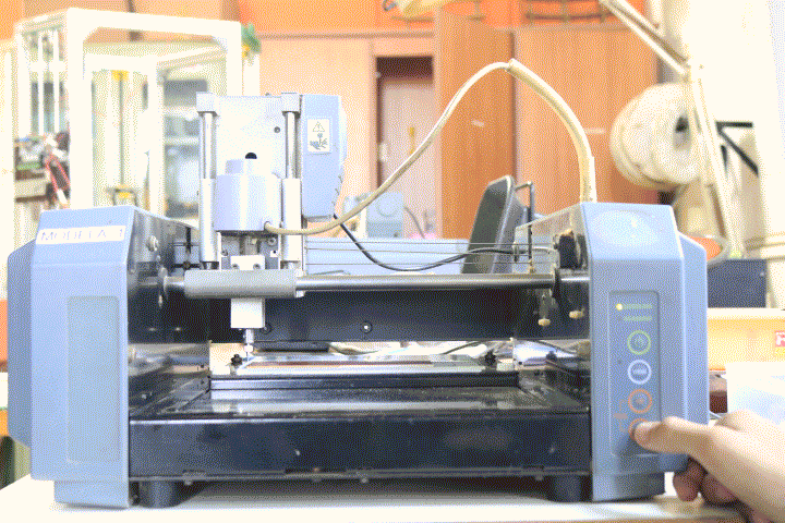
Our local instructor taught us how to use the buttons on the modela machine. namely-
View
Up
Down
Power
There are three LEDs scanning, modelling, and general purpose. One of the important instruction given to us was if some print goes wrong, press up + down till the LED blinks. This basically erases the code from the machines' memory. The next thing we were taught how to set the end mill using gravity. Also I learnt different tasks have different end mills. The 0.4mm end mill is used for creating the traces, while the 0.8mm end mill is used for cutting the board from the sheet.
There are two types of PCB boards available (based on base material). FR1 and FR4, we used FR1 because it is easier to mill and doesn't damage the machine.
To make your MDX-20 ready for milling do the following process:
Press View
This will bring the base plate forward, clean it throughly. Now cut a sacrificial layer of polycorbonate or arcyllic (Non spongy material recommended) on laser cutter of the exact same dimension. Now using 3M PCB tape paste the board on top of base plate.
After attaching it be sure to check if it is flat using spirit level.
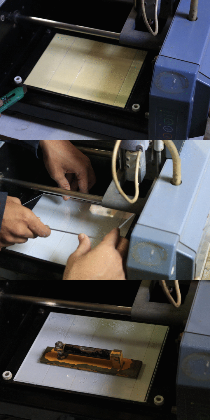
We didn't had the tape available so we had to use a foam tape. This is not recommended and will cause the relative movement in Z direction.
Now take your board and fix it over the bed using the 3M PCB tape.
Press View
This will cause the bed to move back and the tool to come forward.
Attach the 0.4mm end mill, we are done here for now
Now your machine is almost for milling PCBs
Now for the software part-
$ sudo fab
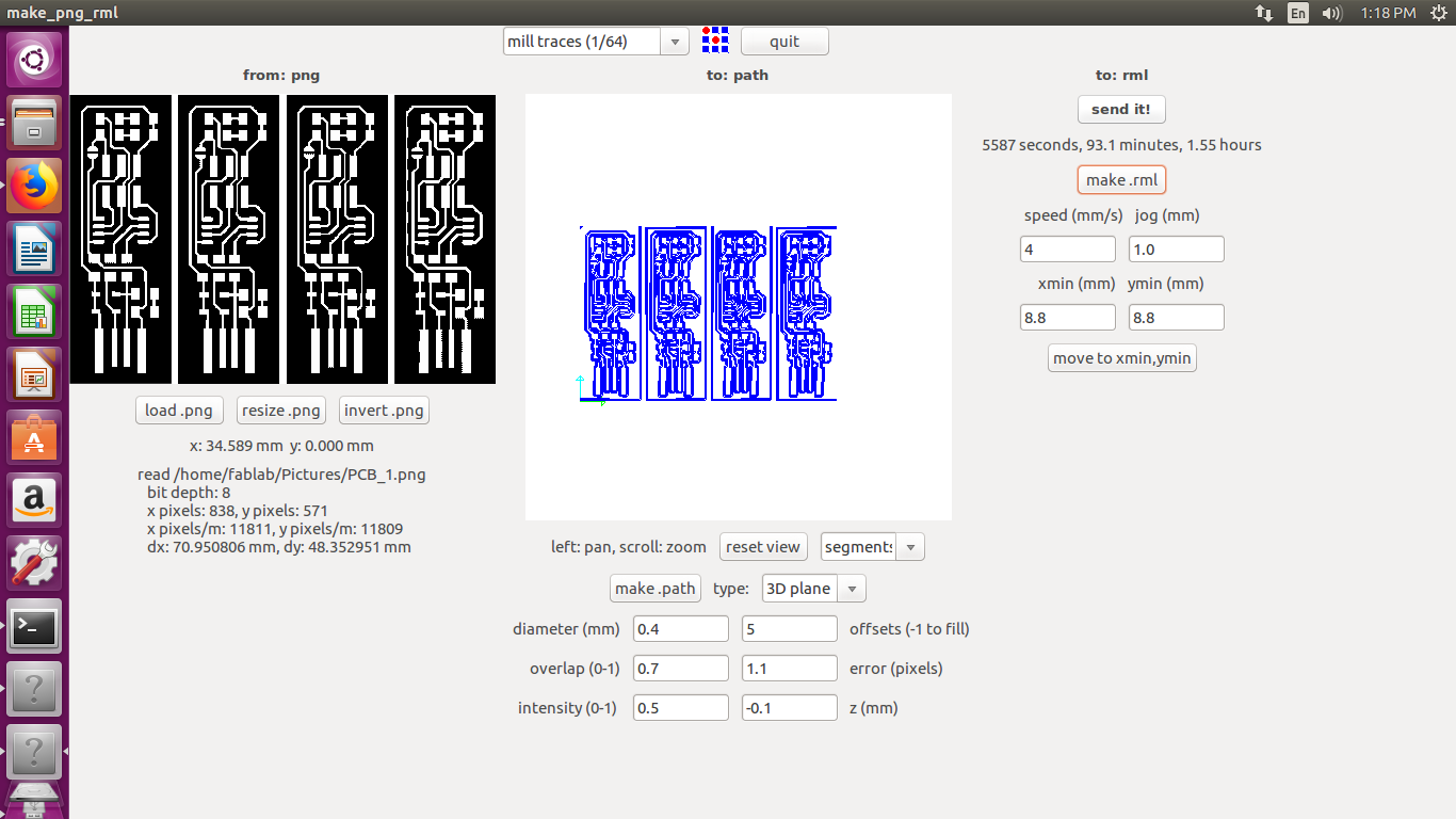
From input format select (image).png
To output process select mdx-20
Being a mechanical engineer, I had little to no experience with soldering let alone SMD soldering. Hence I decided to mill 4 boards at once (4 as it was limited due to the amount of boards that could fit in 1 copper plate). For this assignment we decided to use Brians' board. More information about the board can be found here
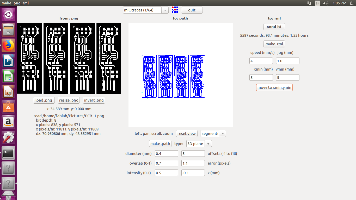
One mistake I made here was I left white space between the pngs, this was interpreted by the machine as milling area. As you can see there is a small border around each of the boards. This will not cause any issue to the main board but it increases the milling time, also reduces the tool life.
Select 1/64 mill traces
Set diameter as 0.4mm
offset = 5
for better looking board go with -1
Set overlap to 0.7
ovelap of 1 means bit will move 0.4mm on each round
I set it to 0.7 as it looks beautiful
click Make .path
You should see the segments, you can play around the parameters and make a board of your liking.
make .rml
the speed and jog are set automatically and do not edit them as it might cause the bit to break.
set xmin and ymin
Such that the bit is placed on the board. Then by using gravity adjust the zero of the bit.
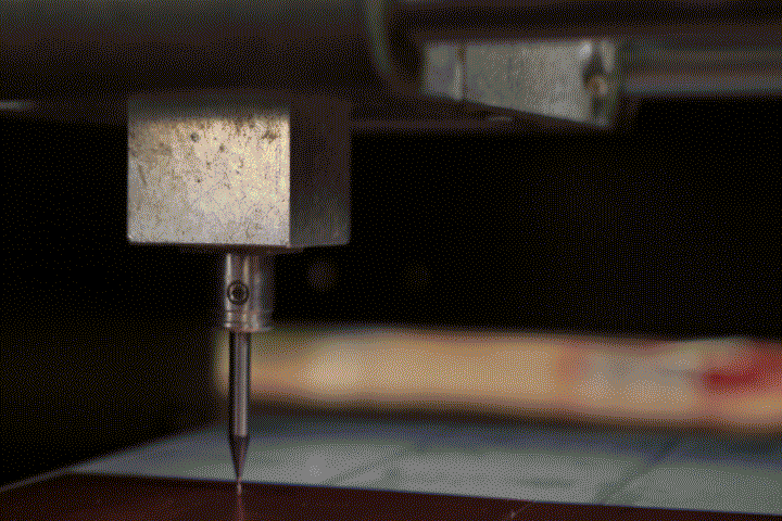
Set xmin and ymin again to one corner of the board.
Send it!
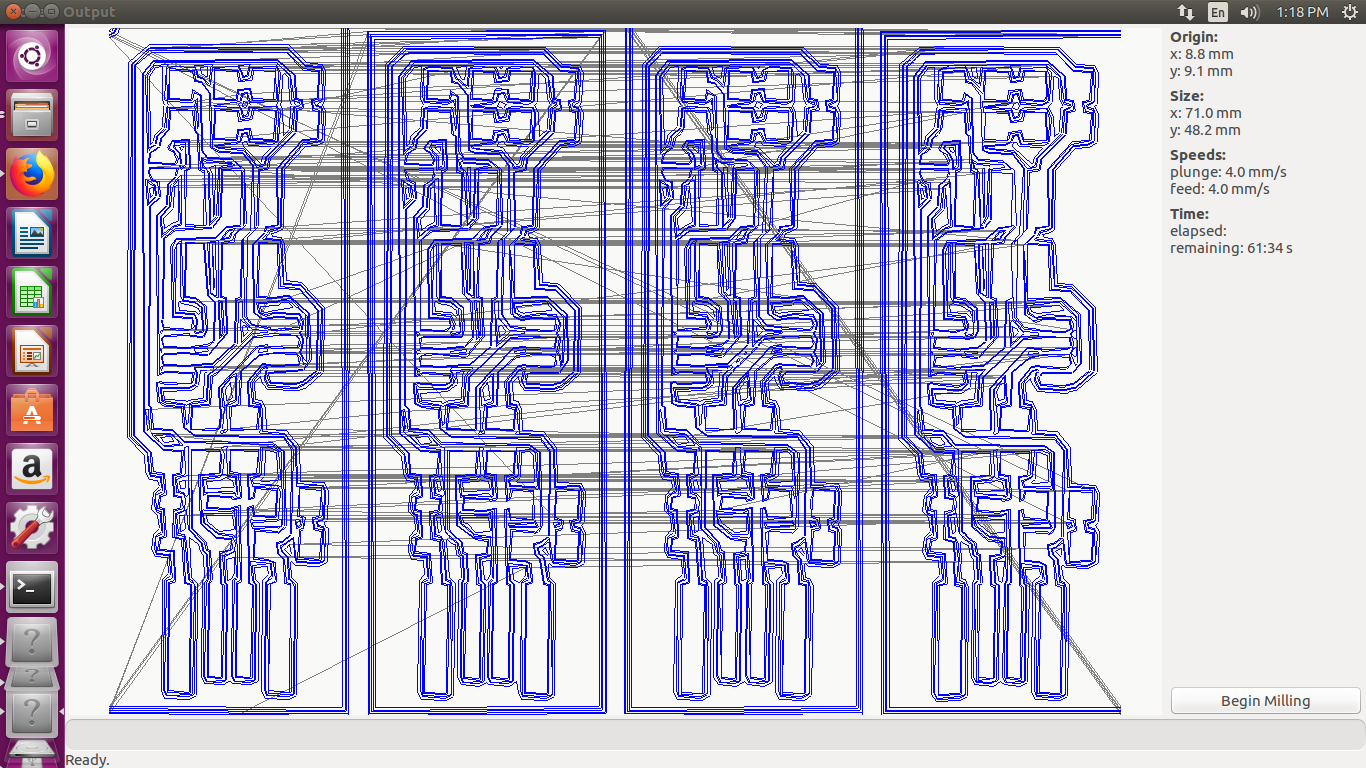
Check origin, size, plunge
Begin milling
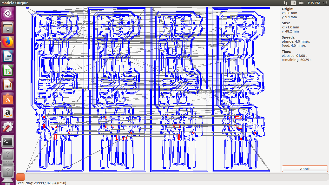
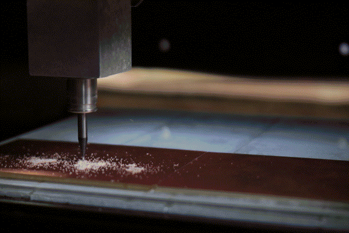
Wait for milling to end.
Exit
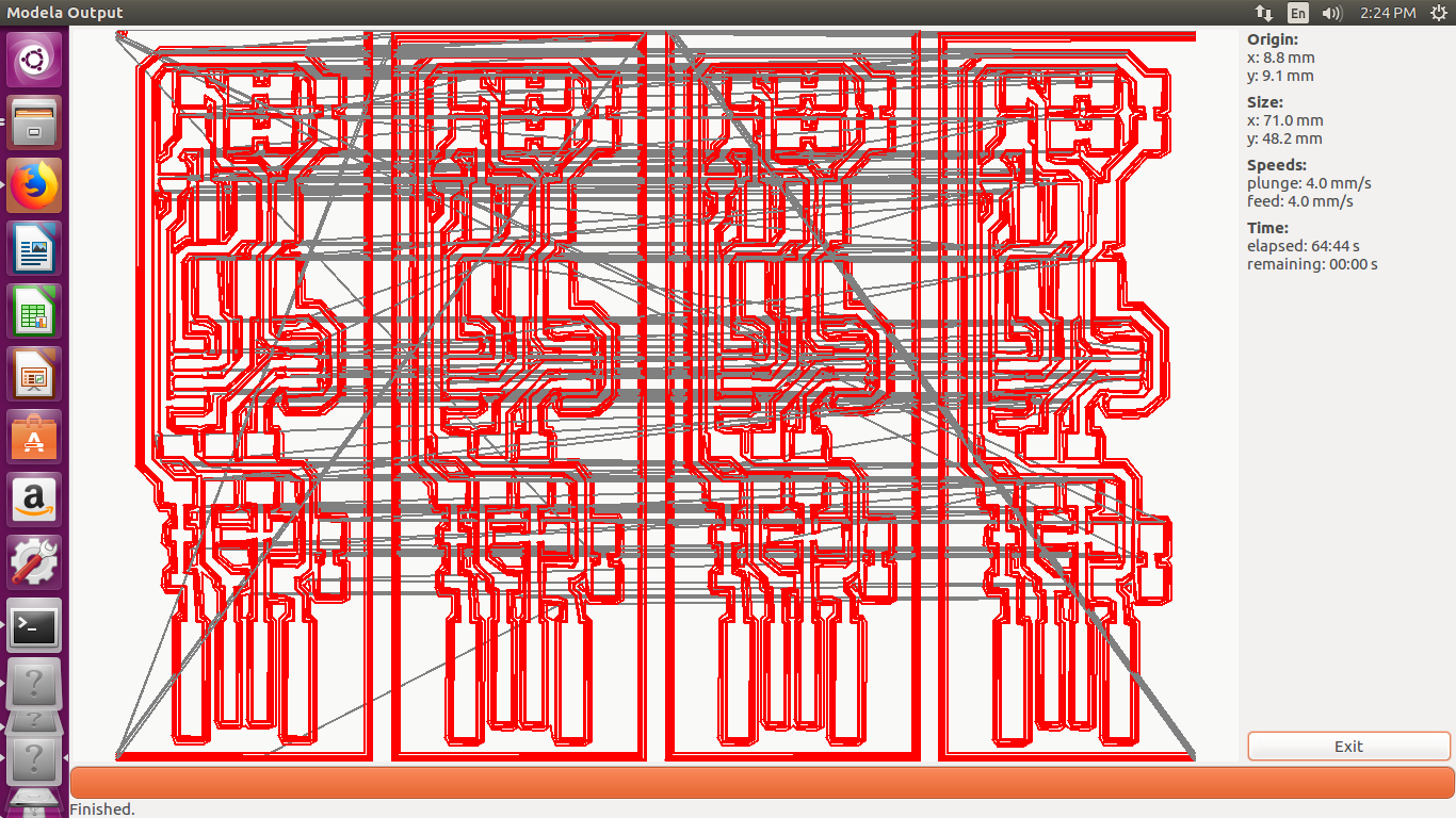
Press View
Now use vaccum cleaner or a brush to clean the board, check if all PCB are good.
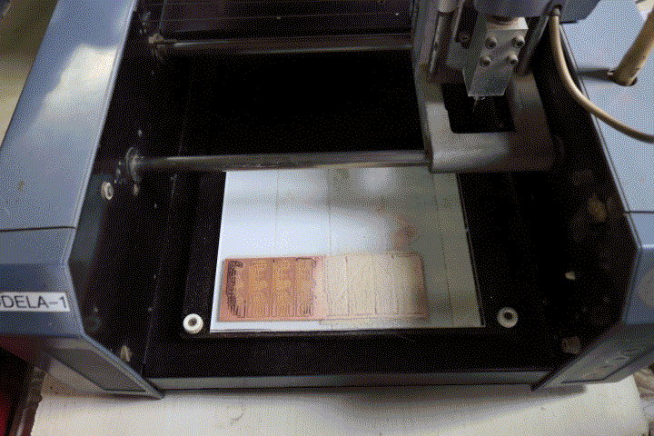
Now select the 1/32 (mill cutout board)

make .path
make .rml
Change the bit to 0.8mm bit and set the end mill by gravity.
send it!
Milling should commence.
Click Exit
Now the boards are ready
Click view
Pry out the boards by using knife. we had used foam tape rather than the PCB tape hence there was relative movement between the board and the endmill this caused many boards to be defunct
We were yold to make the FAb ISP by brain. This can also e solced there
The FABisp by brian has the following components-
- 1x ATtiny45 or ATtiny85 (I used the ATtiny45V)
- 2x 1kΩ resistors
- 2x 499Ω resistors
- 2x 49Ω resistors
- 2x 3.3v zener diodes
- 1x red LED
- 1x green LED
- 1x 100nF capacitor
- 1x 2x3 pin header
After collecting the components, I took some waste PCBs and started soldering practice. I taped my PCB to my table and started soldering. I prefer this method as the helping hands are not stable and kept on moving. After working on 2-3 boards, I was able to get the hang of it.
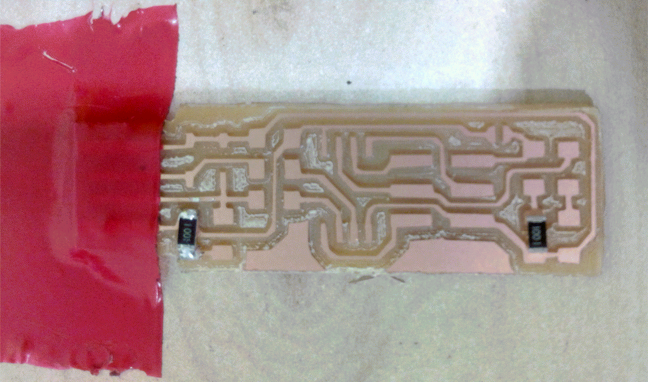
Also we were not having the bent 2*3 pin connectors. So I decided to postpone it.
I soldered all the remaining components.
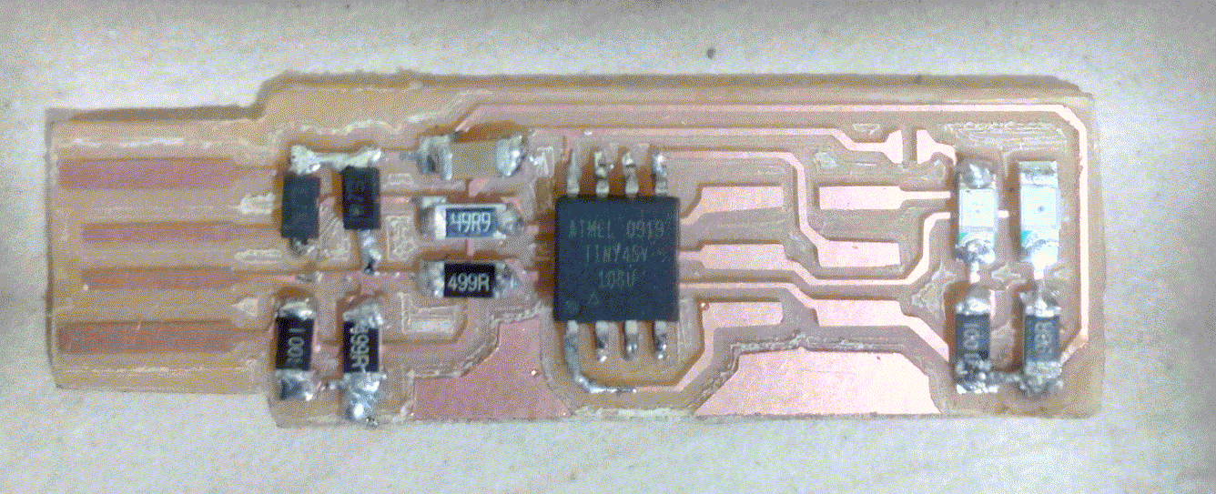
I used the multimeter to check all the connections, and verified that there was not dry solder. Luckily everything was working perfectly.
I have soldered the green LED in place of the RED and vice versa
To build, I used the Ubuntu, rather than Ubuntu on windows
sudo apt install avrdude gcc-avr avr-libc make
Download the firmware source code and extract the zip file (on Linux, unzip fts_firmware_bdm_v1.zip).
Open your terminal program and cd into the source code directory.
Edit the makefile for your board.
For us it was usbasp
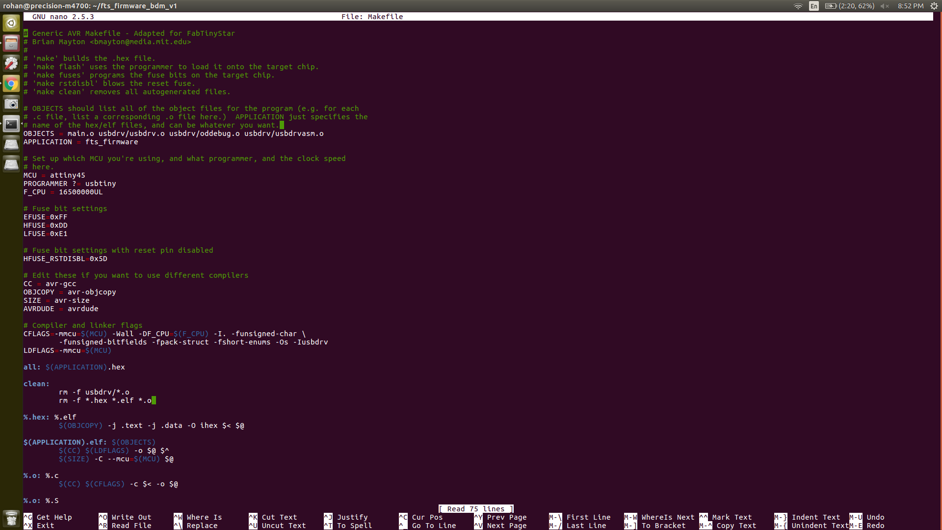
Make Flash
This will wipe the board
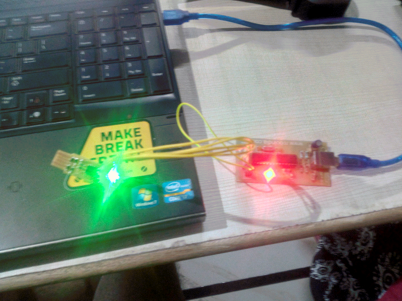
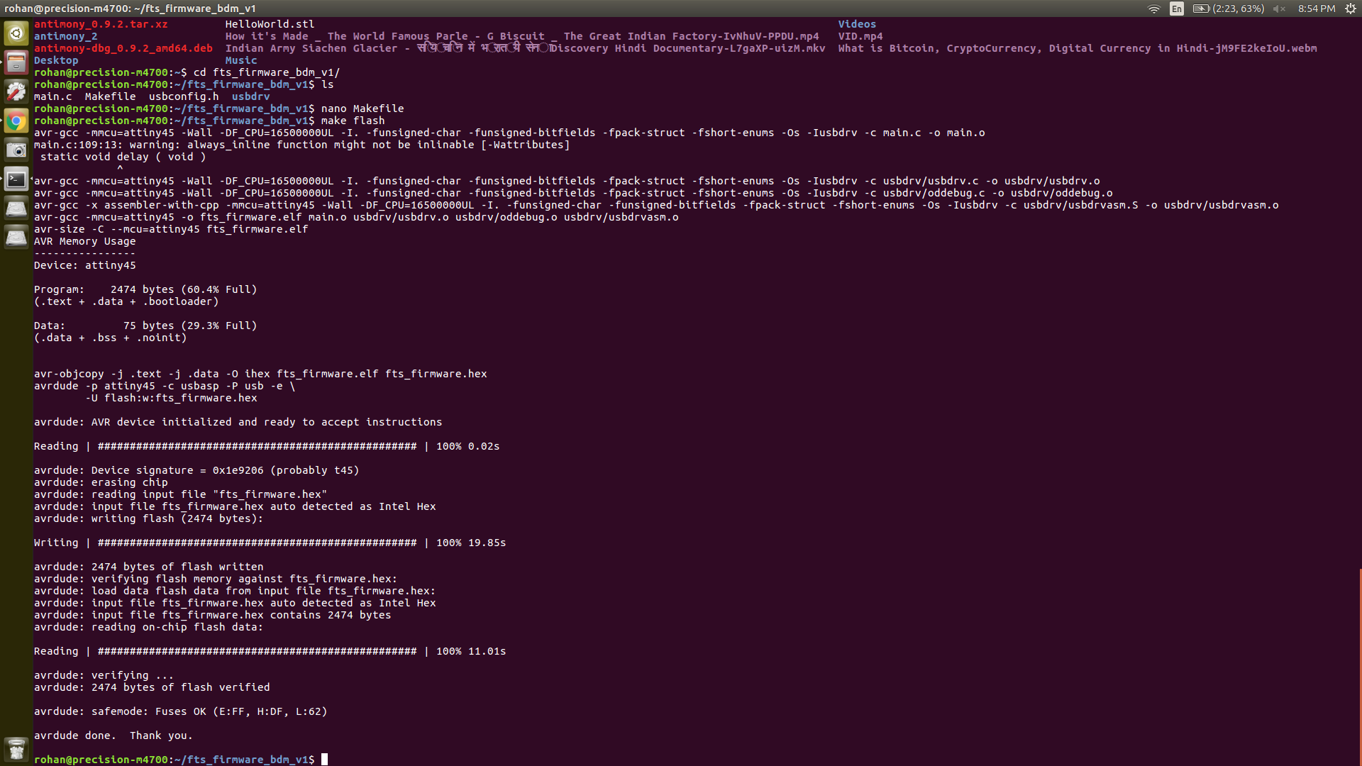
make fuses
This will set the fuses except the one that disables the reset pin
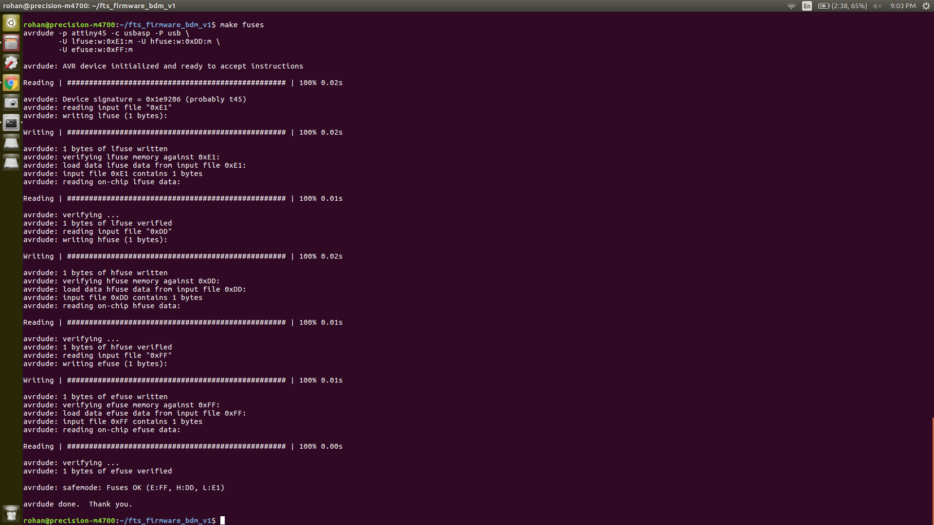
Now test the USB functionality by plugging it into the computer.
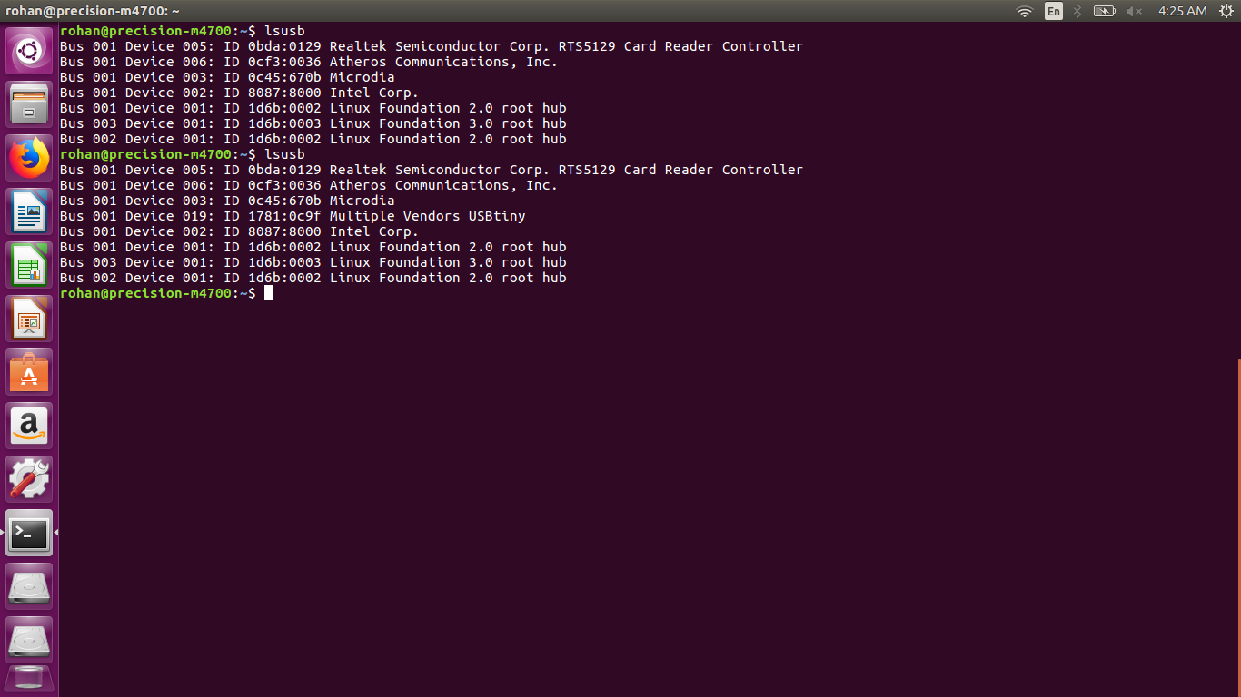
Here I encountered my first error :( ... The green light was on but my board could not be detected in the output of 'lsusb'. The first thing I did was run
dmesg
because, I could see the green light glowing.. So I wanted to see what It was detecting.

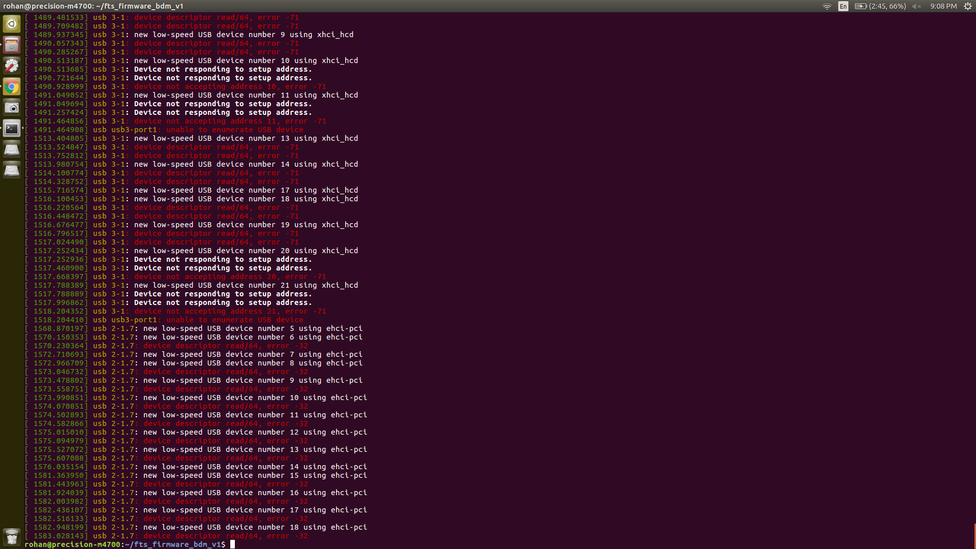
Brian says, It should show 'new low-speed USB device' without any further errors. In my case, I had an error regarding the device descriptor. I decided to check my board again. I appiled solder to the USB pins, checked all connections using multimeter. Refused the solder on all connections using heatgun and solder iron. Again I had the same error. I showed my board to multiple colleagues but still no avail. Until Arefin took a look at it.

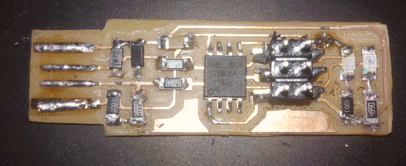
I have use the wrong resistors. R2, R5 are 499Ω which on SMD are 4990 or 499O I can't make out, but I have used 499R I thought they were the same but apparently 499O or 4990 is 499Ω and 499R is 499kΩ. I should not have taken things for granted. Second mistake was that R4 49Ω which in SMD is 49R9 but I used 499R which is again 499kΩ. I replaced them all. With the appropriate resistors.
Bonus!
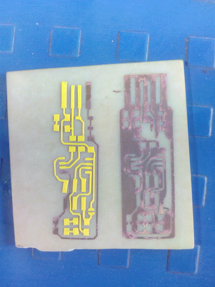
One thing I liked in Fab modules was that, I can use the same .png file for vinyl cutter as well as pcb milling machine. This gave me an idea. I could cut the tracks of fabisp on vinyl and paste them on a copper plate and etch it. It sounded simple, easy and fast.
I thought it would take a maximum of 1hr to completely etch the board.
Excited, I cut fed vinyl into the cutter and cut the png. It was not as simple. I used the same speed/force settings like before. The small traces simply eroded as the blade moved. After 3 tries I finally the vinyl cutter worked the way I liked.
The speed was 3 and force as 110gf (ymmv).
At first I planned to paste the remove the traces from vinyl and paste them individually on a board. It was a massive failure, the vinyl tore although I was delicate. The remaining traces which was able to remove I couldn't paste them perfectly. They were crooked. Being optimistic and over confident, I only had cut 1 vinyl sticker.
The next time, I cut two of them. This time I also used the cut out board .png (the boundary) So I was able to remove the complete fabisp circuit from the vinyl. I used masking tape to remove the whole assembly from the vinyl paper. I folded the free end of tape and stuck the tape to a my table. Now carefully with a pair of tweezers, I started removing everything except the traces from the vinyl (lets call this negative). It is harder than it sounds. There was some error which caused some to tear but they were not the traces.
The whole process took waaaaay longer than expected.
I stuck the negative to a FR1 board.I finally had only the traces
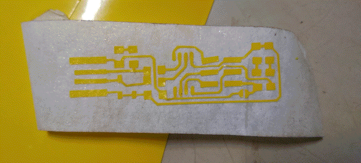
Then I realized my next mistake, and a major one. I had not cut a FABISP board (outline) on modela. Now after etching, I would have to cut the PCB myself. I stuck the vinyl on the board.
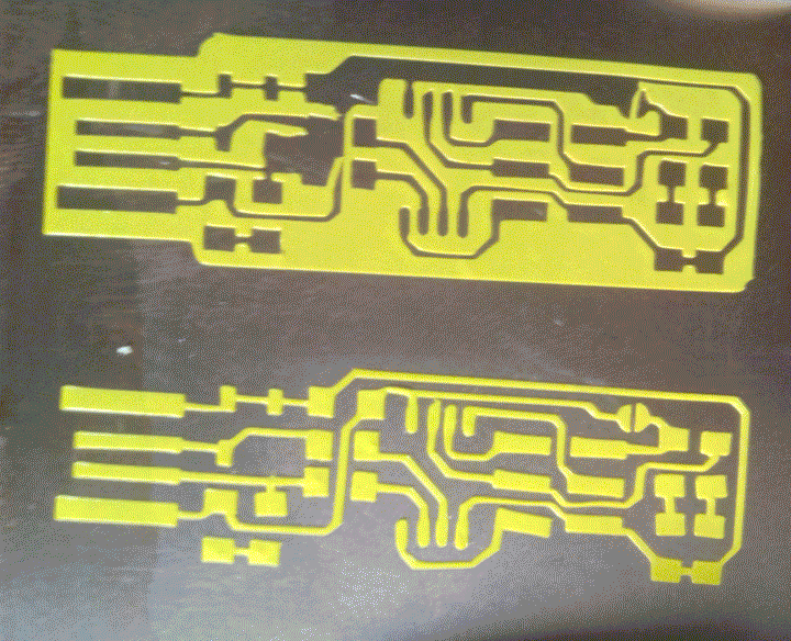
Now for the actual etching part. I have never performed etching myself. Local instructor said, the lab has Ferric chloride for etching. He warned me that, it is dangerous and to be handled with utmost caution. Also, nobody has used the ferric chloride for a long time hence, it be quite old and the solution strength might be less.
I was just gonna place the pcb into a petri dish and submerge it into the solution. When I laid my (gloved) hands on the bottle, I came to know that it was not the solution I expected but a powder. I went back to google and searched the ratio of water to Fecl3 powder. Here I also came to know that distilled water is needed for efficient etching process.
I headed to the INDUSA lab in our campus. Here I had access to all the safety equipments, petri dishes, distilled water, volumetric flasks etc.. I cut the original board using a FERM handheld cutter. I submerged the the PCB in a 50gm + 100ml distilled water solution. The effectiveness of crystals had reduced so I added 2-3 more crystals. After a few minutes I saw some etching start on the edges of the PCB. Being impatient, I added two more crystals. The total process took 1hr and 20mins. But in the end my PCB was ready.
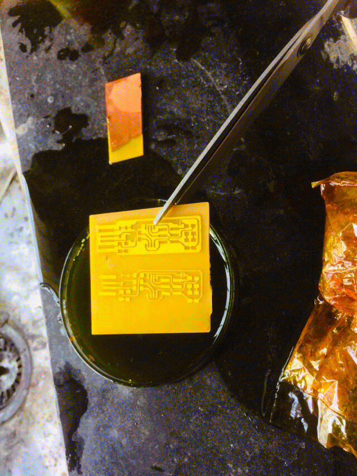
I just needed to peel the vinyl. I removed the board from the solution. Washed it with distilled water and then with normal water.
Then finally removed the vinyl. My board was finally ready. It was too late by then. I decided to solder on the board some time later.
