The render below shows the esthetic level that I would like to achieve in the final project.
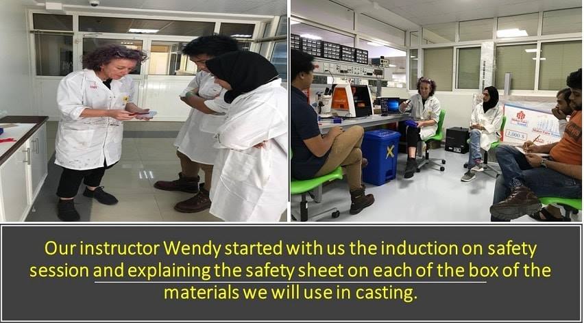
Why to wear safety gear?
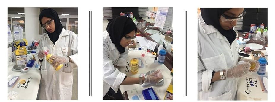
Wearing safety gear is a key thing in our laboratory especially, as I wear safety gear today because the materials we used can cause harm to the sensitive skin. So we use gloves, lab coats and protective goggles when we do mold and cast.

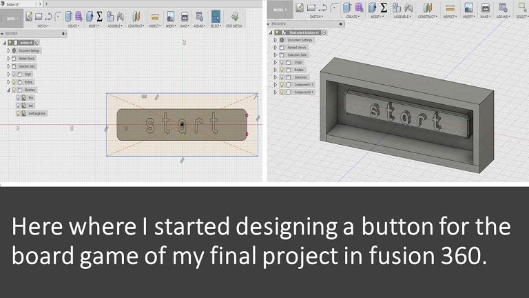
CAD "computer aided design"
Fusion 360, the software I worked in to make my design / the game button. The reason I chose this software is that, in most of my assignments which needed a 3D or 2D design I use to work in Fusion so I’m really comfortable using this software.
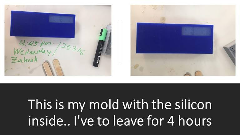
So, before ahead I planned to make a button in this week of mold and cast. to cast a part for a board game of the final project.
Here the steps that I did to design
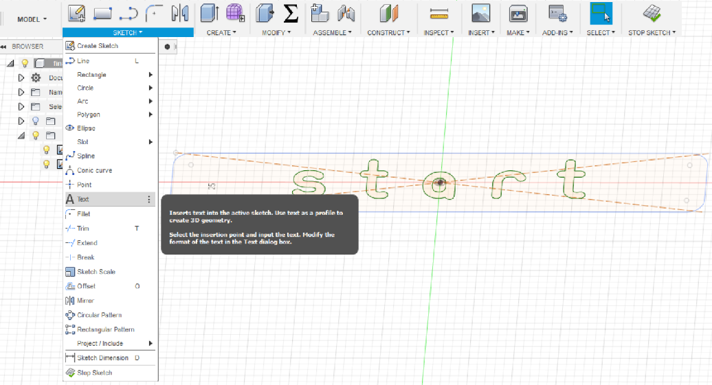
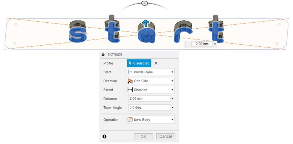
I created a new sketch so I added text and extrude it.
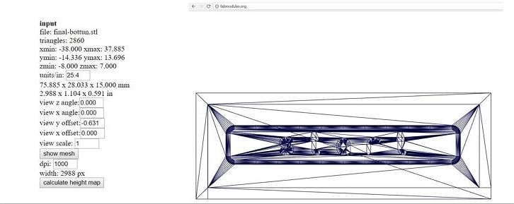
CAM "computer aided manufacturing
I used 2 software to generate the CAM files of my model for SRM-20 CNC machine that we have in fablab UAE which are Roland SRP Player and fab module.
SRP Player is another nice option of Softwares that I learned to convert to file for the Roland SRM 20 same as fabmodules
This is created in fabmodules
I tried two software to generate the cam files which are Roland SRM-20 and SRP Player.
So why I chose the SRP ? I chose SRP Player software because it is faster in calculating unlike fab modules wich takes longer time to calculate than SRP.
I will explain the steps:
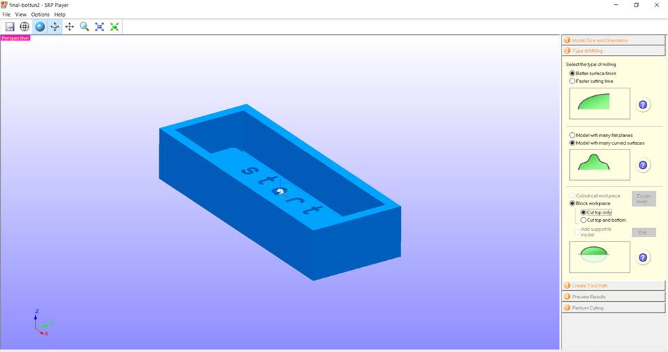
in work space material part I chose the "molding Wax" material.
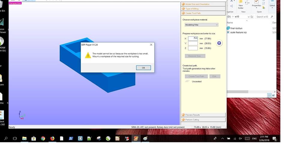
While Im making the file it refused entering the size of the mold because it should be slightly bigger than the mold size,
You can find the dimensions from the scale feature in srp player.
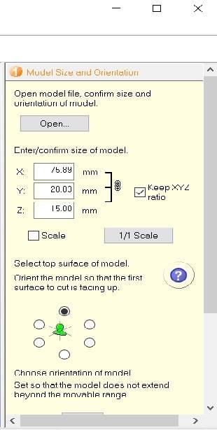
Next is to import the file as stl.
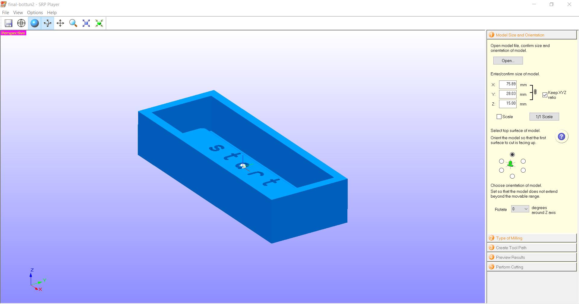
In type of miling I chose better surfece and curved and did not forget to choose the option cut only.
In this picture, the dark blue colour means that this is the part to be milled so we have to keep a margin and you can adjust the width, height and length from x,y,z in prepare the workplace area.
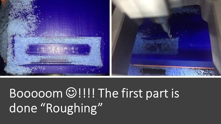
in the third step which is creating a tool path we have two main options 1. Roughing 2. Finishing.
Roughing is the first step before finishing which takes most of the material to achieve the desired shape and here you can see that the ending result has more geometry edges and shapes, But when you do the second step the finishing comes cleaner and better and the desired shape becomes with smoother edges as well.
Roughing setting
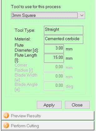
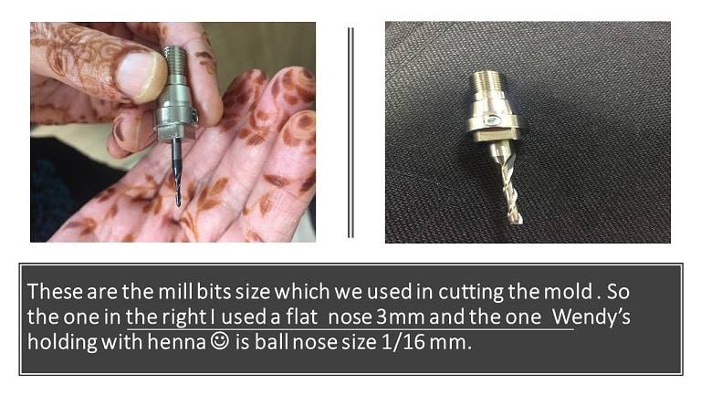
I chose 3mm mill bit
If you do not find the mill bit size which you looking for you can add that from the list given by going to 1. options 2.my tools. So you will have the tool type within the options. Look at the given image here.
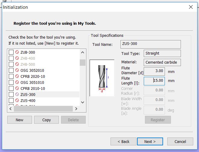
Tool type is 3mm straight
 These are the cutting parameters for roughing1. These are the default setting for the selected material according to the software database: feed rate 1440 mm/min, spindle speed 7000 rpm, cutting in amount 0.60mm, path interval 1.80mm and last the finish margin 0.20mm.
 Preview roughing
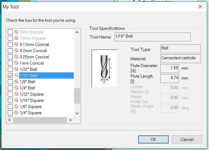
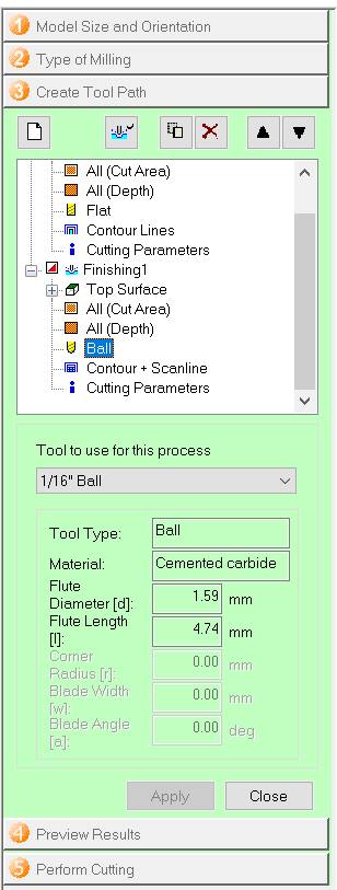
Finishing step, the used mill bit size here is 1/16mm ball nose for finishing.
I mentioned the same thing above for adding the tool type from options and selecting the size and name of the tool you want. 1/16mm ball nose the one I will use.
 Finishing - ball- 1/16mm
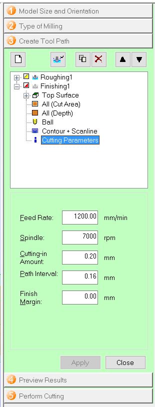
The parameters for finishing are less than the previous one "roughing". Also, these are the default settings feed rate 1200 mm/min which is less than the feed rate in roughing, spindle speed 7000 rpm is same, cutting in amount 0.20mm because the tool that is used in finishing is smaller.
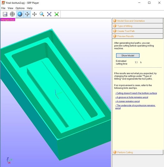
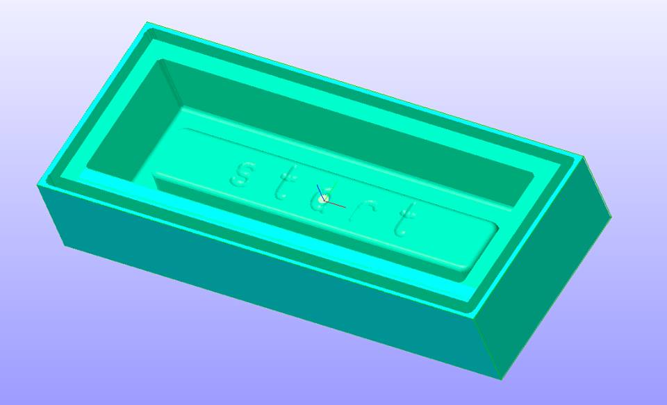
Go to show model to see the approximate shape of the cut.
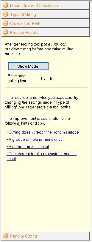
Preview before the cut .
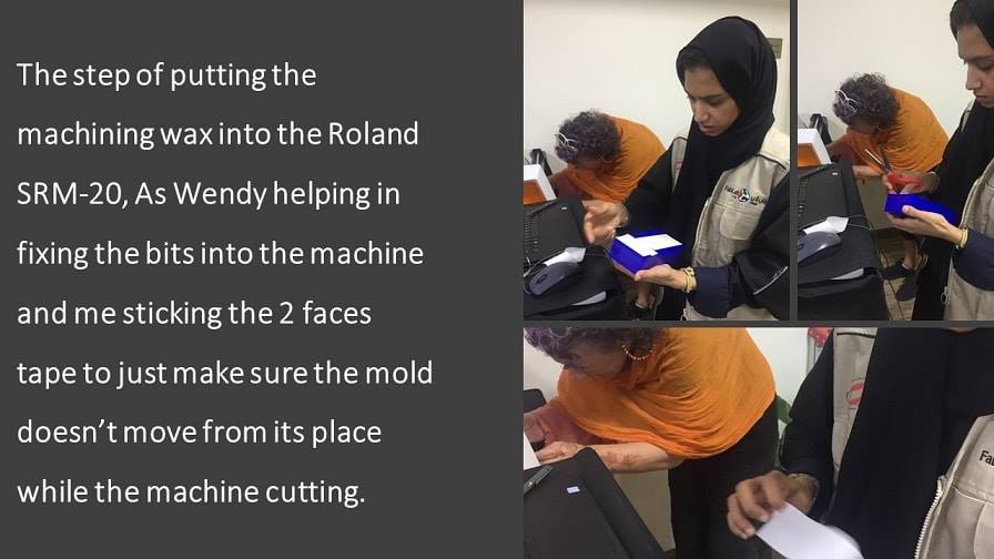
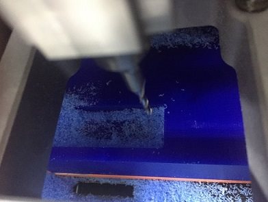
cutting step
Well, before I move to the last step of mold and cast, I would like to mention the problem I faced!.
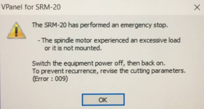
We had a lot of visitors in our lab that day, So maybe because of nervousness, I put the wrong mill bit !!!
Instead of using (1/16) I used (1/64) for making my mold
 AND I put the wrong setup of the Z axis as well which is not the right choice at all hhhhh!!
*accident* happens !! So, when I started the Roland SRM 20 I freaked out from the sound which came from mill bit hitting the bottom of the mold and what made me more freaking is that everyone around just left what they were doing stared at me jajaja@_@ !!!! Even Wendy heard that noise from a distance and of course, she came and she was saying “it’s alright, relax,... it’s alright, relax “hahaha and thanks GOD the problem fixed without any injuries -the most important thing-
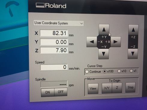
I had this message
This was the settings which I made mistakenly
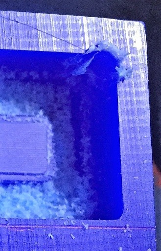
The result!!
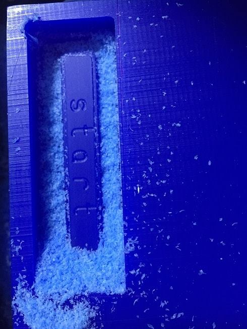
This video is after fixing the problem "changing the mill bit and X,Y and Z axis.
- Back to the design -
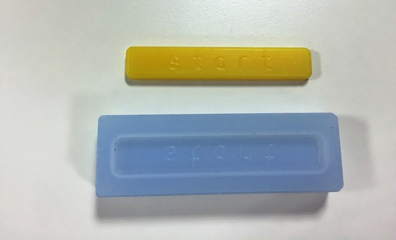
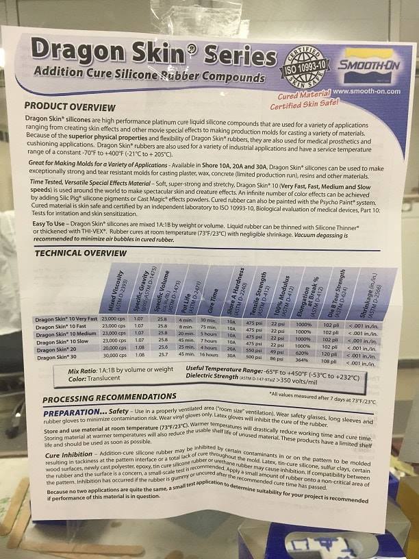
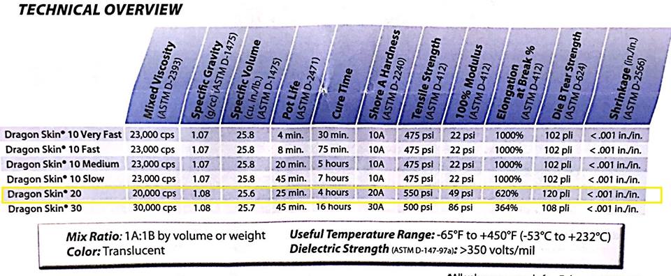
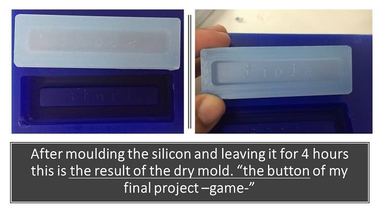
After engraving the model inside the mold, I followed the instructions from the sheet, the Dragon Skin 20, which I'm using to make the last part or cast of my design.
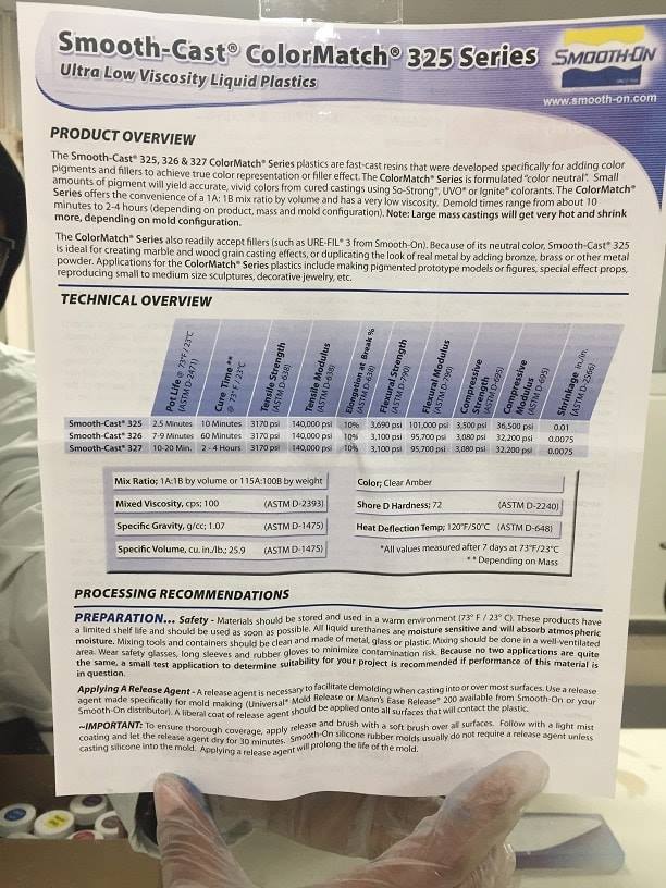
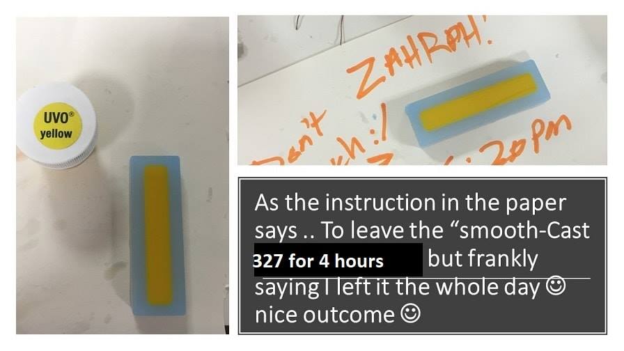
So, as I'll be mentioning this again in the coming steps,we believe that the store sold us old resin, because the cure time was approximately 10 minutes, not the 4 hours stated in the sheet below. We had to work quickly.
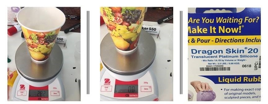
Pouring the silicon and weighing
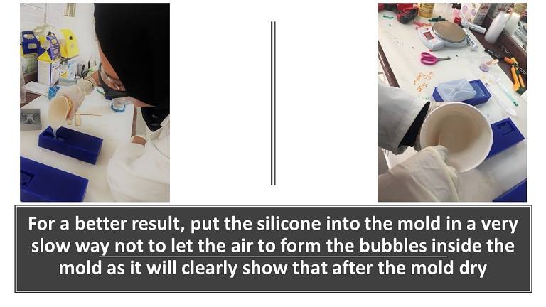
Casting
The yellow colour have been mixed by 3% of the weight of the silicon liquid and mixed well and should be left for 4 hours.
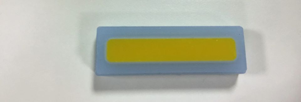
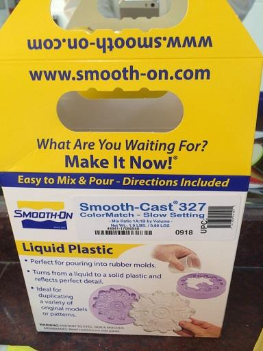
Now casting the liquid plastic after mixing it with color and puring it in the silicond mold to have a solid part at the end
The final result