Embedded Programming
Assignment
-Read a microcontroller datasheet
-Program my board to do something
Read a microcontroller datasheet
Files
.ino-file blink with pin-numbers changed
hello.arduino-files: c, make, hex
Before I started to program the board I needed some knowledge of the components and microprocessor we are using and its specifications. For doing so I read its datasheet, in my case the one of the ATtiny44 trying to extract the main information of it. An important thing is to know wich pins you have in your microcontroller and where you have connected to the components that you work with. In my attempt to getting to know the possibilities of the microcontroller and the ATtiny44 I had to understand how the pins of the microcontroller were laid out so that I would be able to program them.
The pin numbers I would have to program in a software on a computer is not the same as the number of the microcontroller on the actual board. This is because some of the numbers are used for other things than programmable pins. In the tutorials section of the Fab Academy website there is a good schematic showing the pins of the ATtiny44 microcontroller and its correspondent pin in the Arduino software. Looking at page 2 and 3 in the data sheet we see the reason why the pin numbers are different. Pin number 1, 4 and 14 are used for VCC, GND and reset which is why they are not programmable pins and therefore not usable in the Arduino software.


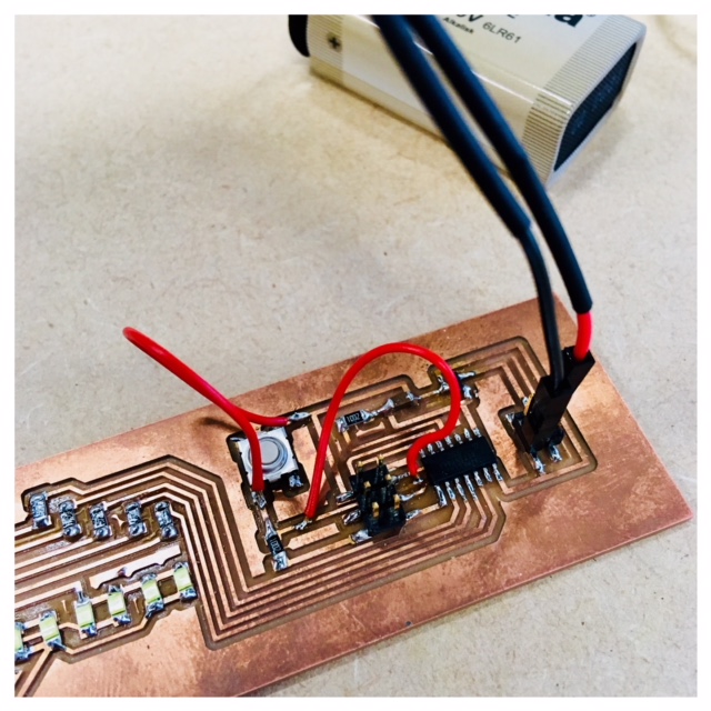
When I startede out programming my redrawing of the Hello Echo board I had some trouble with my fabISP-programmer so I used a MK2 programmer that Lorenzo had, but I started out using the drivers for my ISP togehter with the box and that went terrible wrong. I could not get anything to work, so we decided to talk with Bas Withagen and he help me change the drivers for the right one. I got my bord blinking with the Arduino software and a simple code (code included in the top of the site) for programming. I was one of the basic-code examples in Arduino IDE, I just needed to change the pin-numbers in order to the schematics and microcontroller datasheet (see pictures in top of the side).


Next step is to get my fabISP working again. I think I need to tjeck my soldering and try to use the multimeter before starting up with the progamming again.


Programming my output board
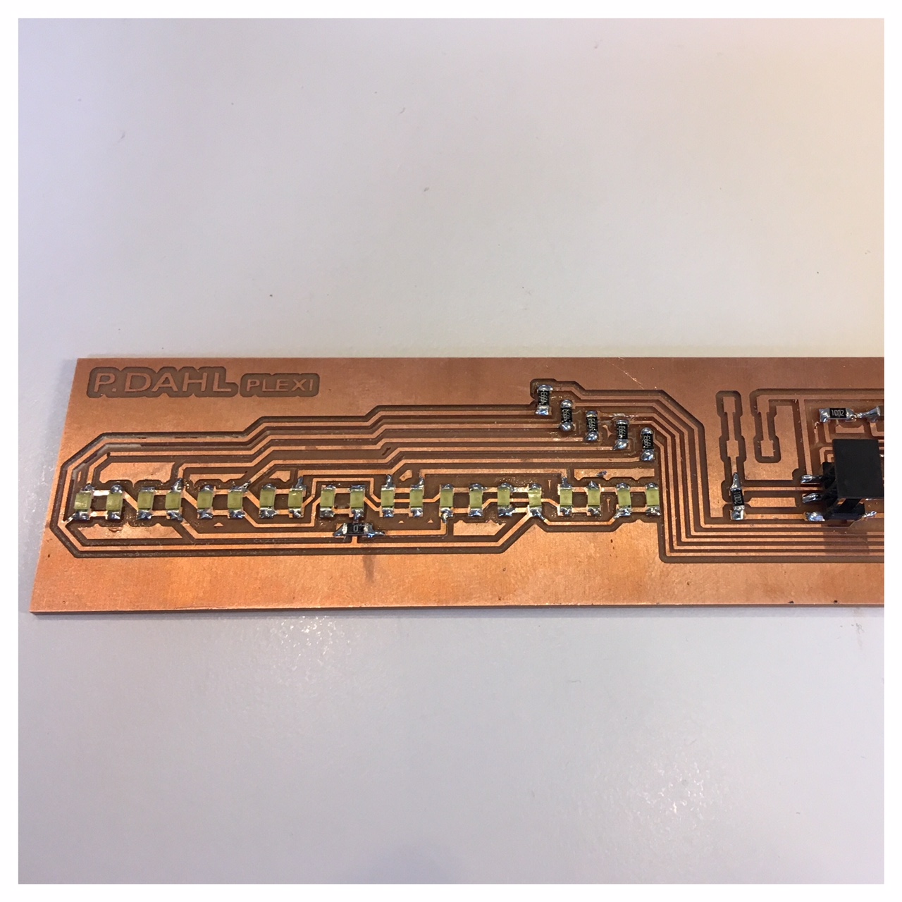
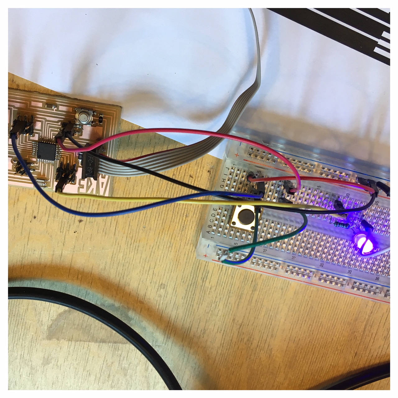
I burnt bootloader on my board and pushed the makefile and c-code for the board to make it Charlie Plex and everything went smooth, but sadly it didn't light up, something was wrong. I checked the traces and the LED's with the multimeter and cheked the schematics again and it all loked to be okay, but it still did not light up. Suddenly I discovered that it was lighting up but very weak. When I hold my hand over the LED's I could see it Charlie plexing but very week. So I was wondering if the missing brightness could be about the voltage regulator and came to that conclusion that I would change that. Then I found out together with our instructor that the 5V voltage regulators were put ind the wrong drawer. In the 5V drawer lay the 3.3V including the wrong datasheet and vice versa, so I soldered the wrong voltage regulator off and soldered the right one on. Sadly it still light up very dim, so I'm not done trouble shooting.
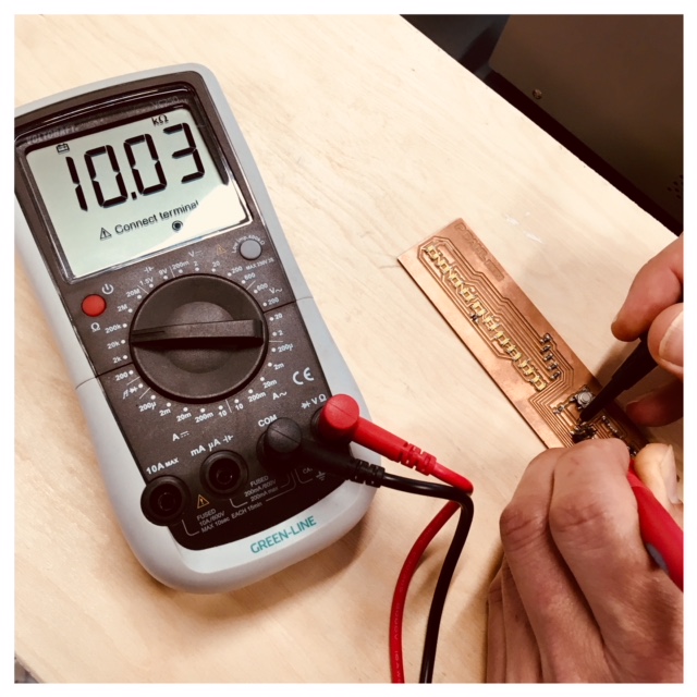
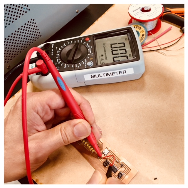
I tjecked again with the multimeter and but on power to the board from the DC power supply we have in the lab. From this machine I could control the voltage and the ampere. I found out that there was one trace that went through the header that was working similar to a recistor. I soldered a cord to the trace and made a bridge. This helped and the right amount of voltage went through the trace now. I also tried to solder a bridge over the pushbutton because it seemed at bit less responsive.
Watch the video below of my Output board, LED array, Charlieplexing.
Tinkering with the teachers at a local primary school
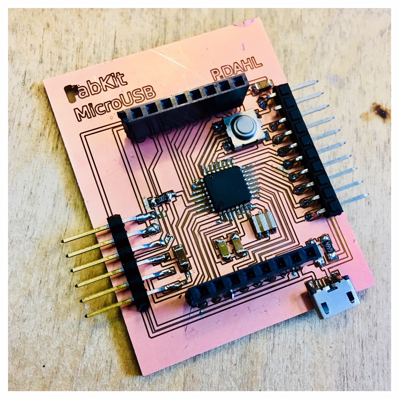
After good amount of meetings and tinkering together with teachers at a local primary school and some facetime meeting with Heikki in Finland I realized that I will get the best result for this first product with a board where the teachers also could do some experiments. Here I was quite inspired by Neil Gershenfeld's talk about Seymour Papert's Seymour Papert attempt with the interactive turtles and the importence to make the kids make the interactive turtles. I think it's important to get the teacher to make their own version of the lamp, with their own design and connect it to my main lamp for creating the network. My thoughts are here that the teachers then later on can experiment with the kids. In this way, I think I would have the opportunity to pass a learning experiment rather than just giving them a finished product. So my dream is that this could be a course in the primary Schools' Maker Spaces that I work with, where students produce and experiment with the lamps that are connected to other lamps in other school labs.After my meetings with the primary schools teachers I decided to try to make a version of a FabKit 0.4 board and a version of the Satshakit board and burn bootloader as an Arduino so the teachers have the opportunity to use Arduino IDE for programming. My reason for doning this is a hope for getting teachers to code/program more in the schools Maker Spaces than what I see today. The few teachers who do a little coding and programming in the primary schools in Denmark are familiar with Arduiono IDE and in this way I hope that this project can make them work more with mico controllers and IoT projects with the children. So a kind of kickstarter project for them to engage in.
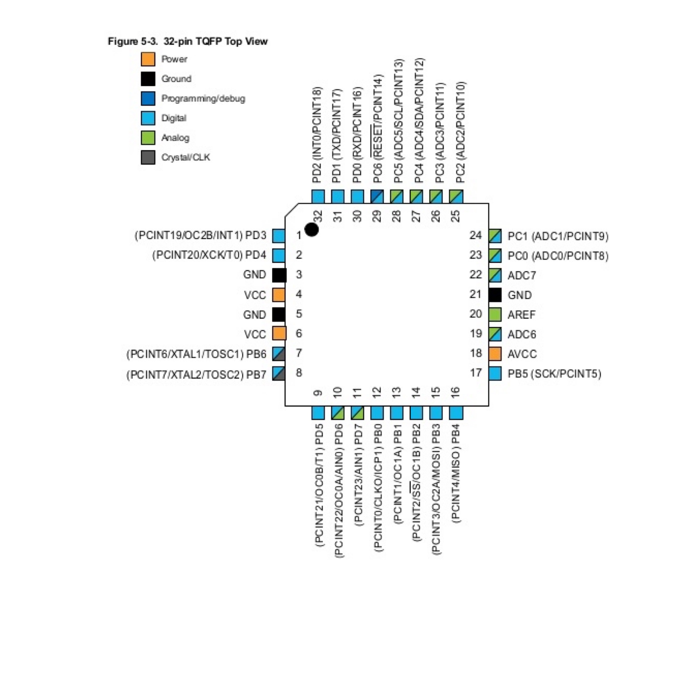
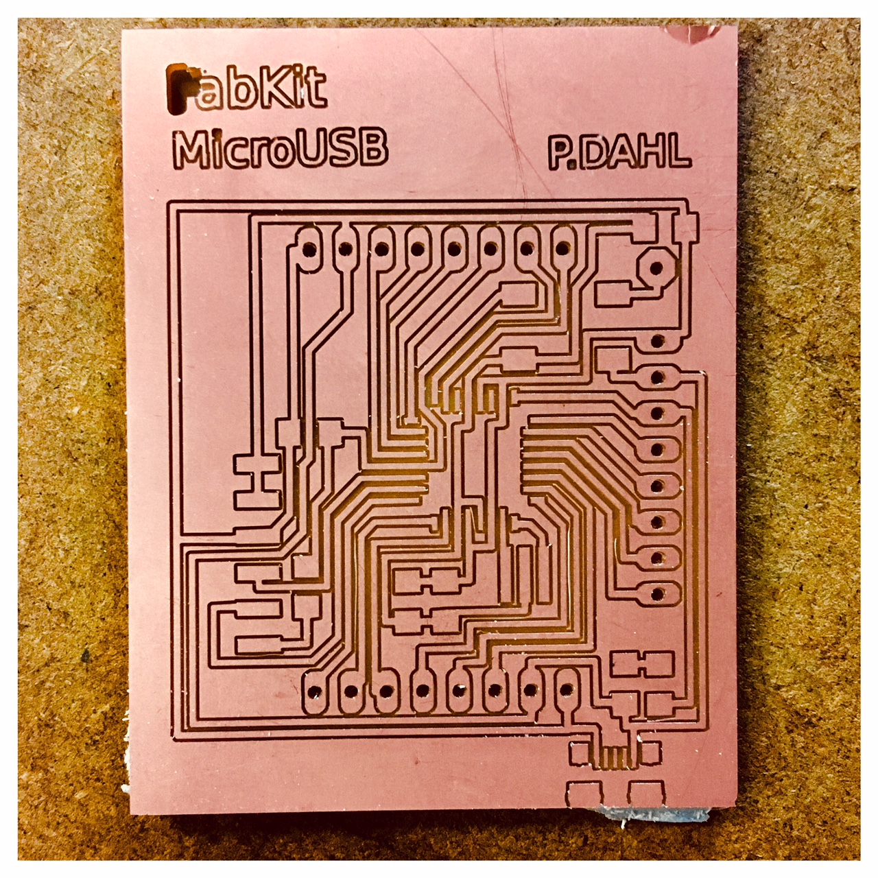
I started out with reading the datasheet for the ATmega microchip (8 bit, 32 KB) that was the microchip used in bouth boards (the FabKit 0.4 and the Satshakit) trying to figure out where each pin went and what it could be used for. I found this little great picure at the ATmega that was really helpfull.
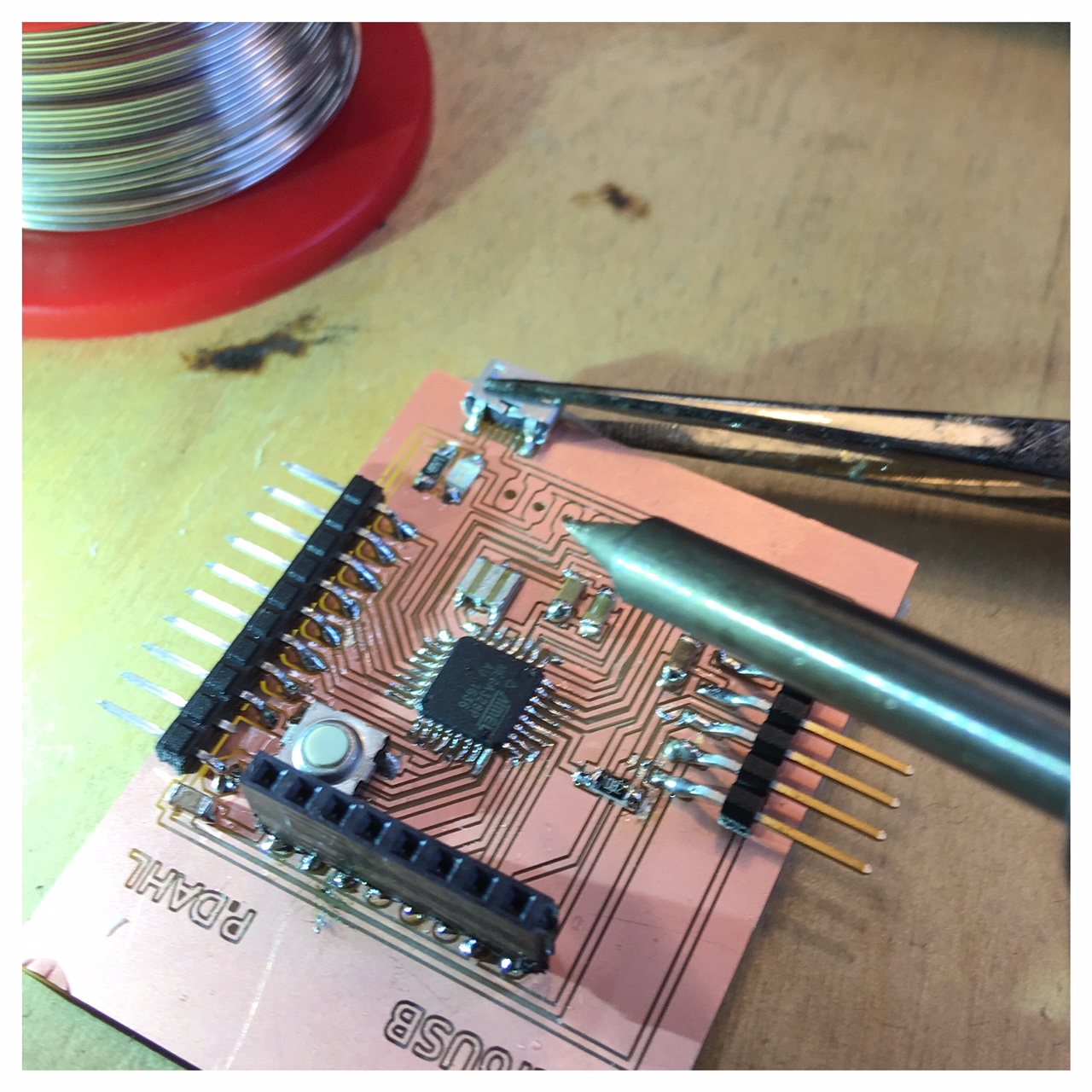
When I came to perform the various steps in relation to "burn bootloader" and try to upload code, FabKit started to smell a bit and "magic smoke" occurred, oh no! Then there was nothing to do, it was burned. I realized that I must have done something wrong with the connection of the GND and my FabKit. I therefore chose to make another Fabduiono model (I thought I might as well try to make another model, when I had to make a new one anyway... long live variation).
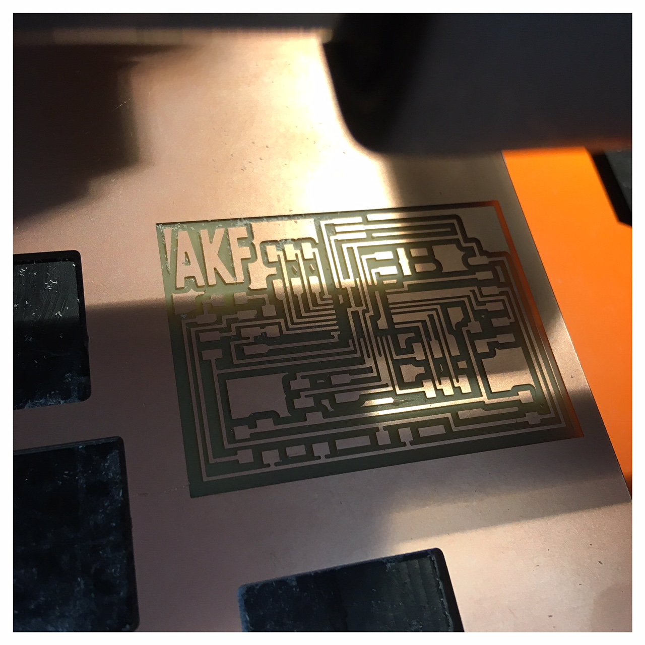
I decided to make an AKF Anna Kaziunas France Fabduino; because it looked quite small and I really liked the documentation/tutorial site of Anna Kaziunas France (check this link): Tutorial site of the AKF Fabduino
This went a lot better. I milled, soldered, burned bootloader and programmed the Fabduino with some basic code examples form Arduino IDE in one day. I will use this AKF Fabduino to become wiser on the code sections related to my lamp projct and to find out what I need (or may be without) in relation to my Final Project.
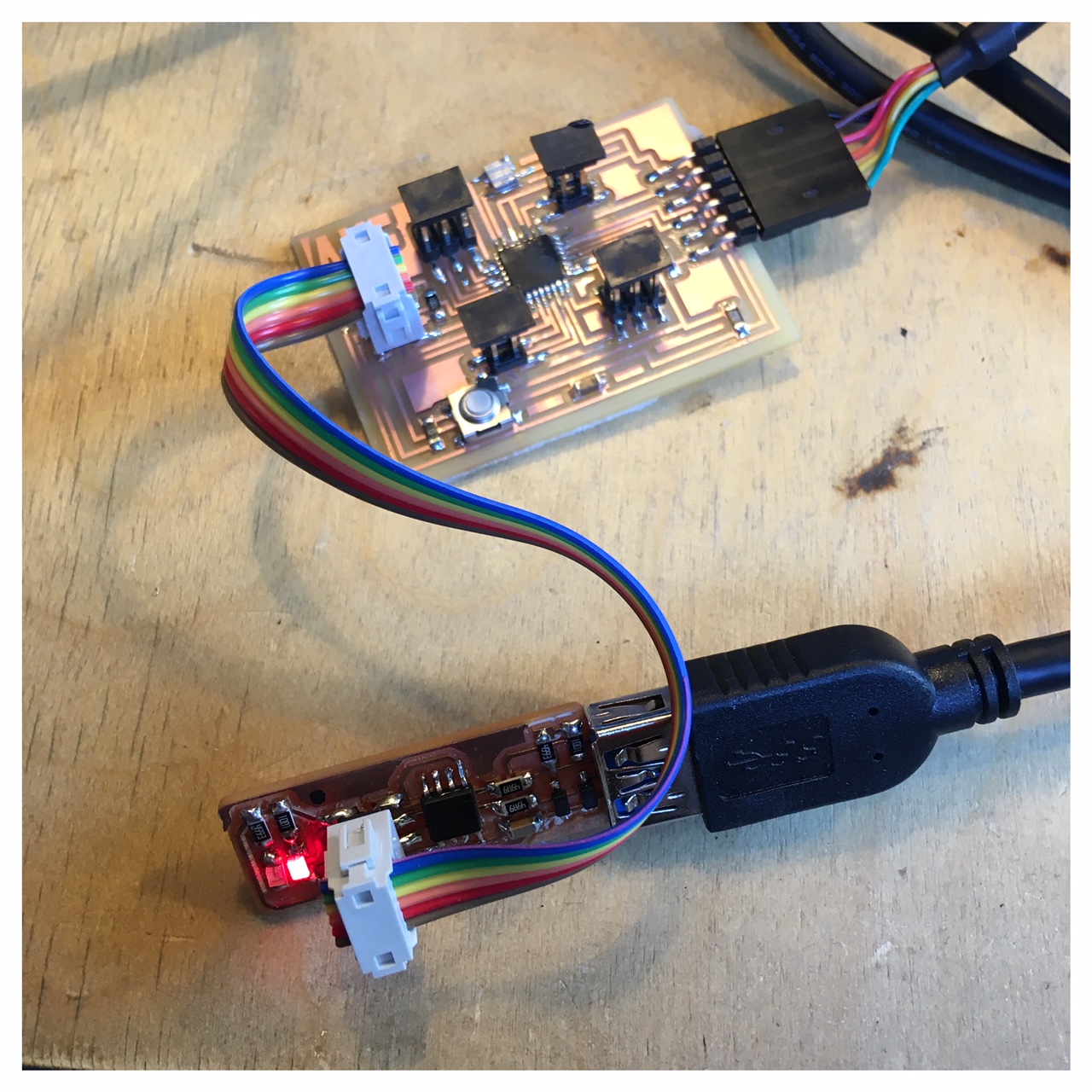
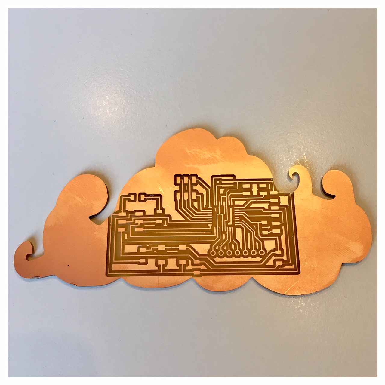
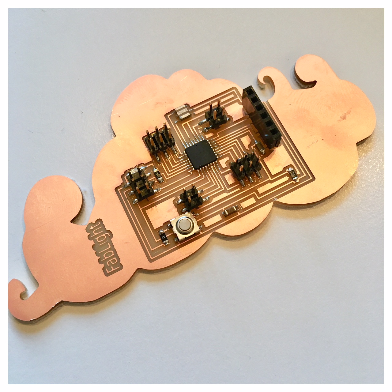
Hart & Brain
After working with the AKF Fabduino and the FabKit that I made I wanted to try putting my own little touch on a Fabduino-version. So for the hart and brain in my lamp I created this little Fabduino with my handdrawn cloud as the frame. I also attached a female socket for the FTDI so I later kan plug in my ESP-module. I made sure that every pin was available so I - and others - have the opportunity to continue experimenting with the lamp. I think in time the students should be encouraged to hack the lamp, giving it some of their own soul.
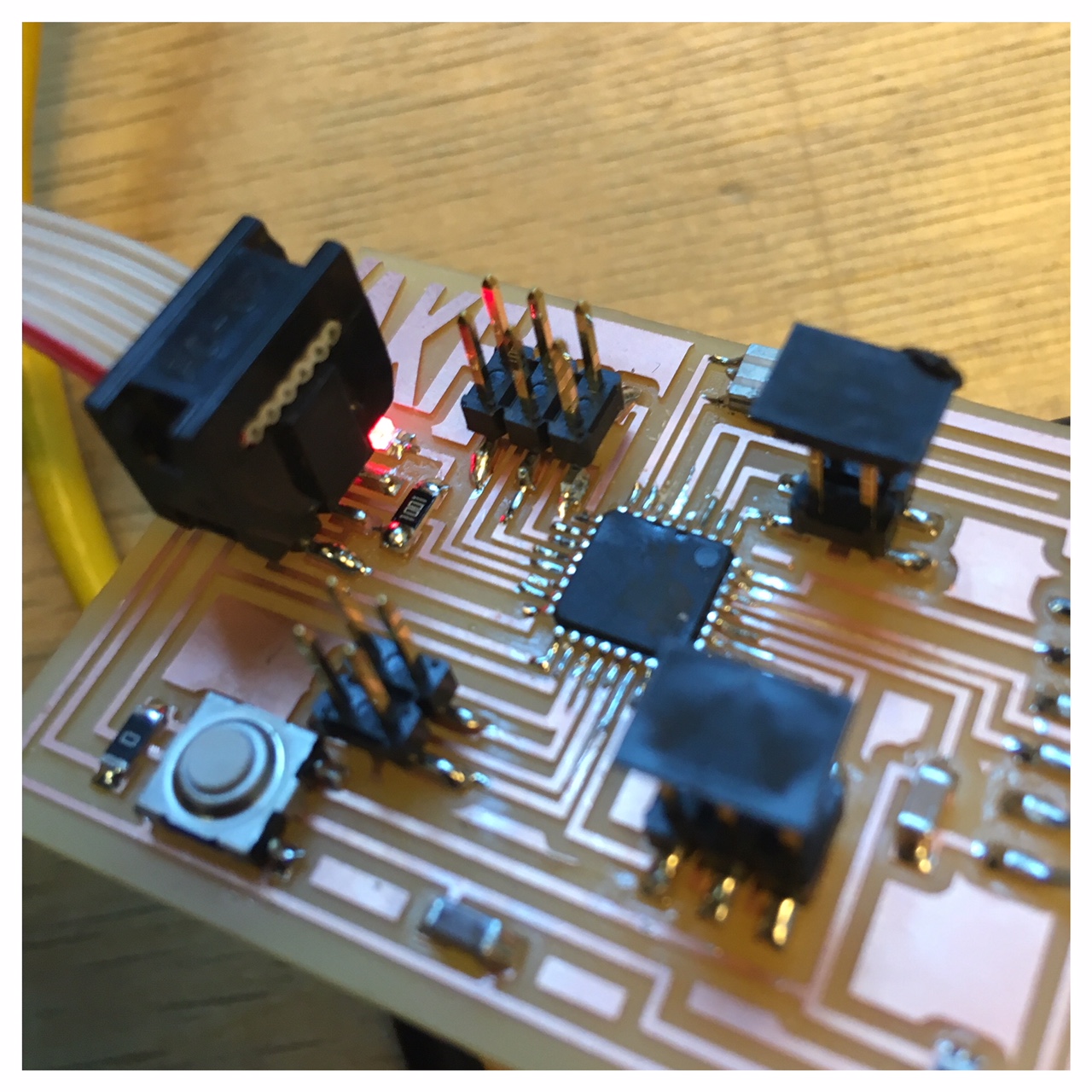
Coding and programming my board
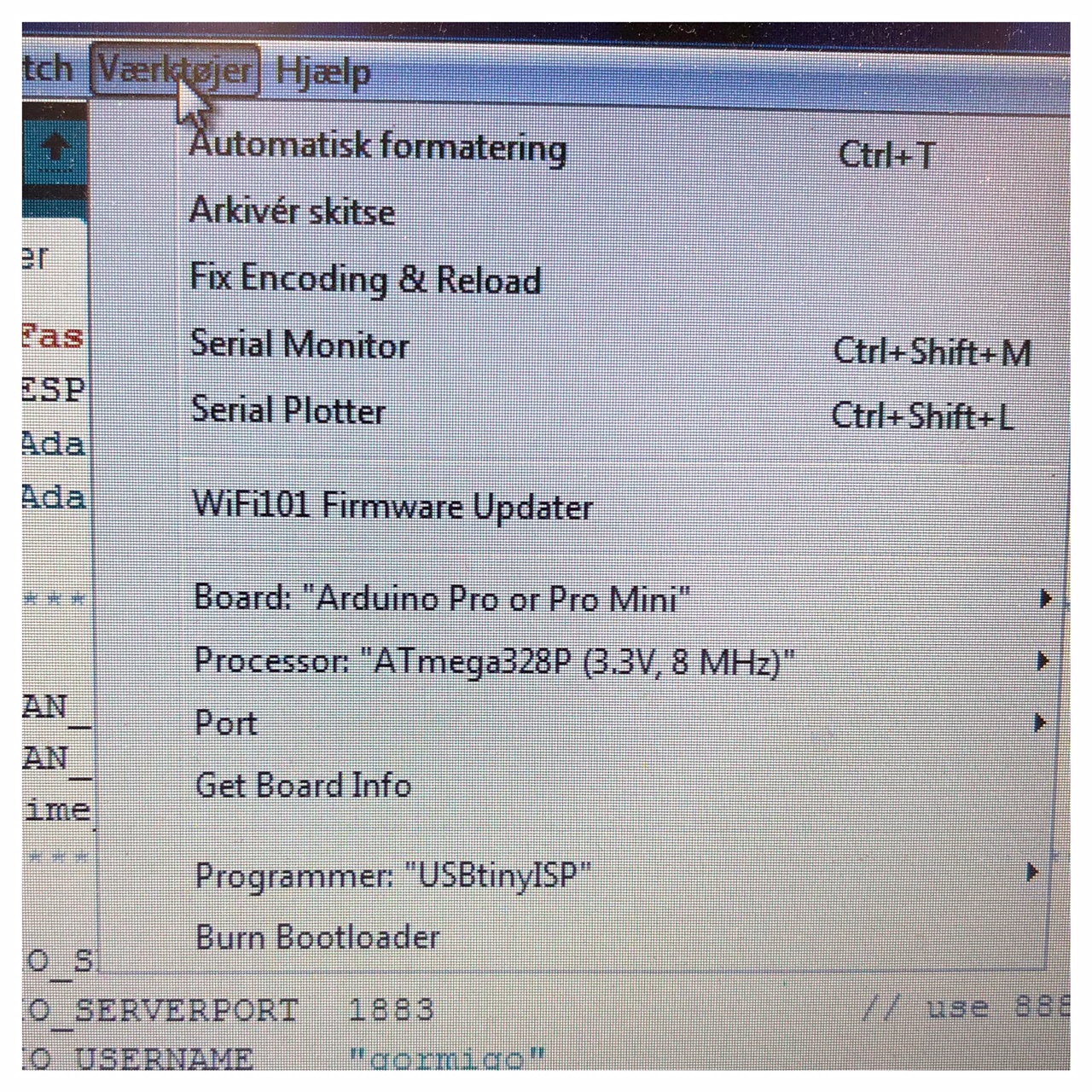
So I burnt bootloader on my version of a little Fabduino. For this job I used Arduino IDE with the folllowing settings under tools:
board:"Arduino Pro or Pro Mini"
processor:"ATmega328P (3,3V, 8 MHz)
portThe port that appears when you plug in your board, in my case port3
programmer:USBtinyISP
And then "Burn bootloader
When this was done I neede to read the datasheet for the ATmega328P chip and find out with pins I had available. So my traces, the datasheet and with ins can I use. I modified some basic code examples in the Arduino IDE under: files, examples, then 01.Basics and 02.Digital and it worked on the board. I just had to change the pinnumbers.