Mechanical Design
Group assignment
- design a machine (mechanism+actuation+automation), including the end effector.
- Build the passive parts and operate it manually.
- Document the group project and your individual contribution.
Link to our group website:
Individual assignment
I am working on the Z sliders and the holders in the bottom (that holds the wheel for the belts)
Files
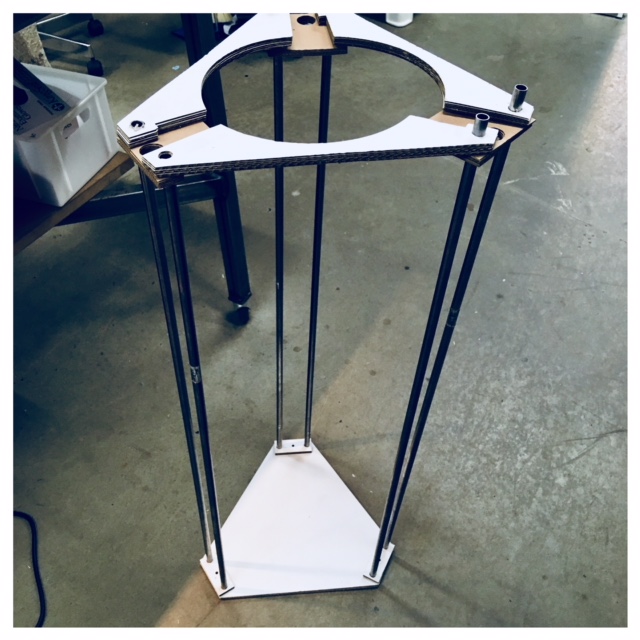
The Clay Printer
For this week we all decided to help Carina (our fellow student) with completing the machine parts, electronics and frame for her clay printer Carinas Final Project The machine is going to be a version of Jonathan Keep's 3D Delta printer for ceramic. Jonathan Keep's 3D DELTA PRINTER FOR CERAMIC
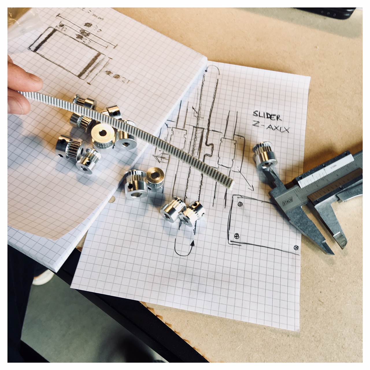
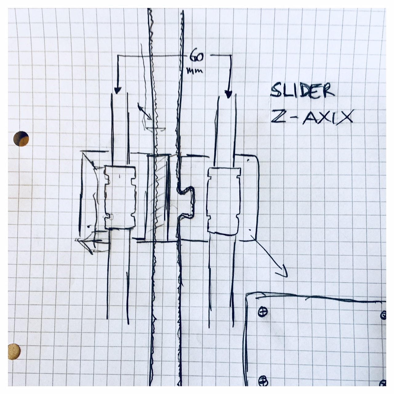
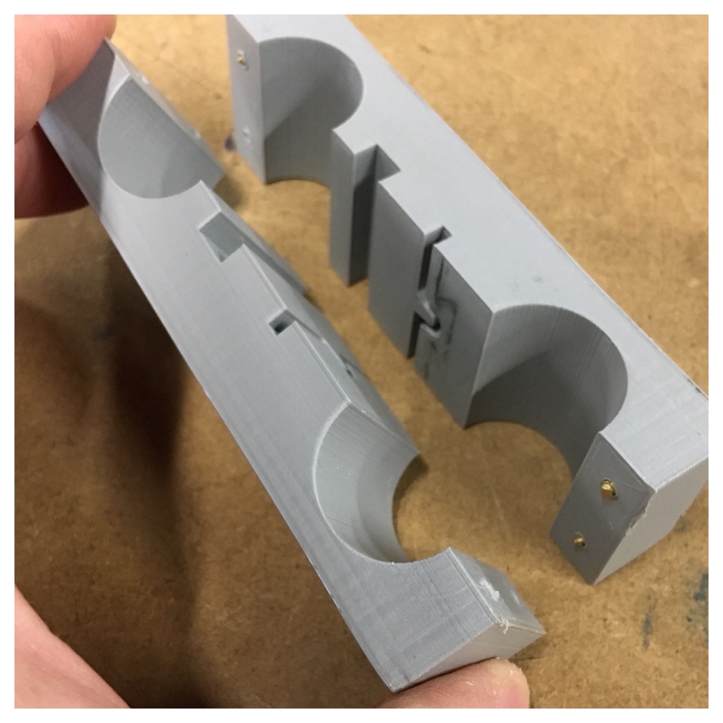
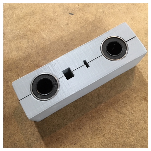
Carina showed us all her ideas and inspiration, and to get started we divided some tasks between us. A fellow student -Anders Alnor and I- got the task of figuring out the slider part for the Z-axis and the mechanical parts for the servo motors. In the clay printer that Carina got her inspiration from, the sliders for the Z-axis were a laser cut piece of MDF with the linear ball bearings stripped aginst the surface. So Anders and I thought this could be a place for small improvements. We decided to make a 3D-print design that could encapsulate the ball bearings and avoid the strips (cf. the above sketches). After a while with sketchning and talking we went to the local hardware store to buy screws, nuts, bolts and other small things we needed for our design.
3D prited Z-axis holder
I decided to print the z-axis holder using the 3D printer of the Lab (An Ultimaker 2). I printed in grey PLA. If I had the opportunity to print in nylon based material it would have been great because of the strength of the nylon material. PLA is more fragile than nylon, but it is easy to work with when you are prototyping. I have read about nylon printig. That the nylon is tough and partially flexible, have a high impact resistance and a good abrasion resistance.
Dividing tasks
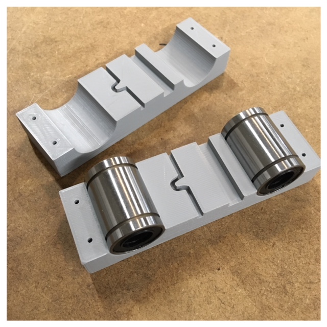
So Anders and I had to devide the task of making this z-slider so that we bouth got hands-on time with the software (In this case Fusion 360). We ended up agreeing to sit together and this way getting the most out of a joint dialogue. Then we decided to split the z-slider between us meaning I drew the right part of the z-slider and Anders drew the left part of the z-slider in Fusion 360.
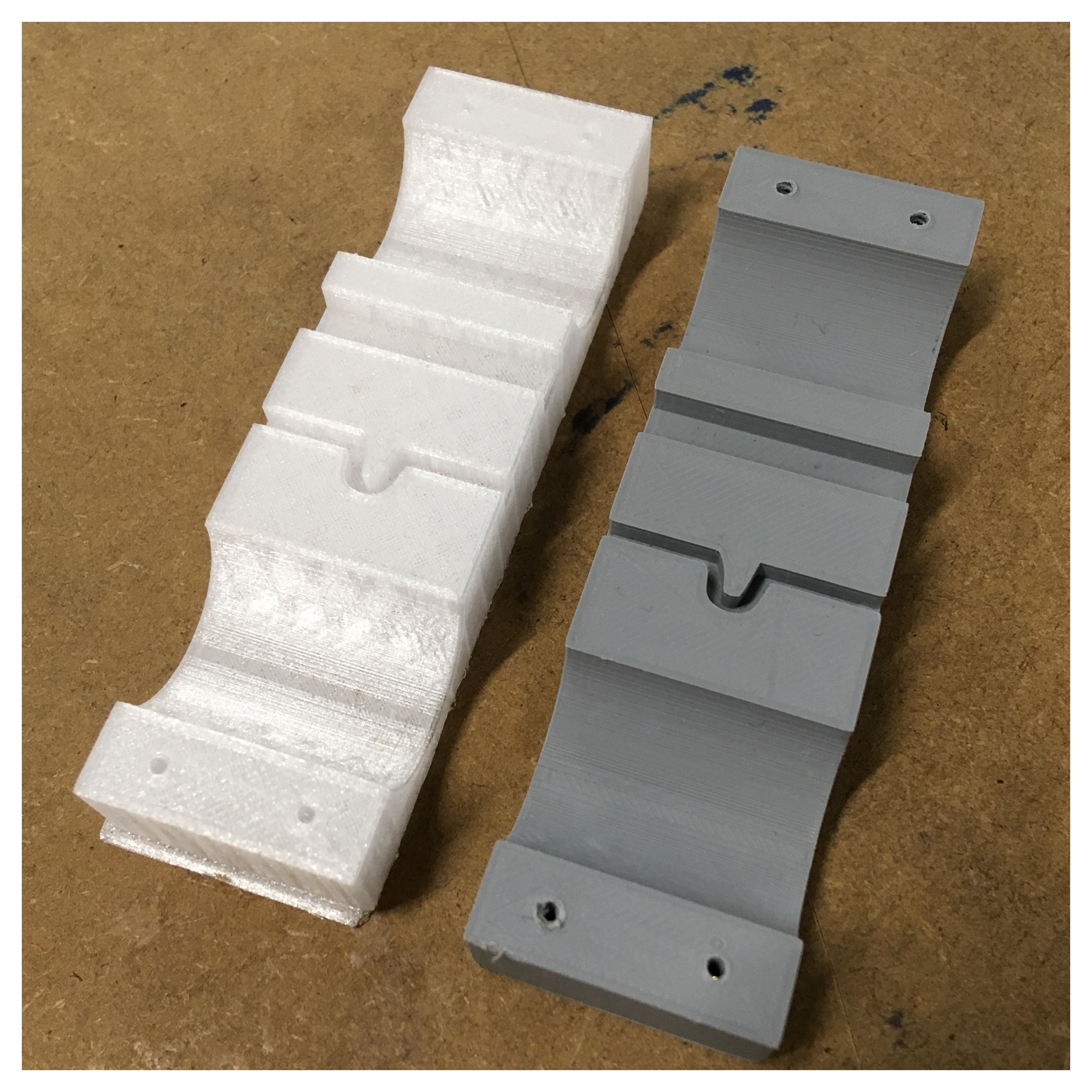
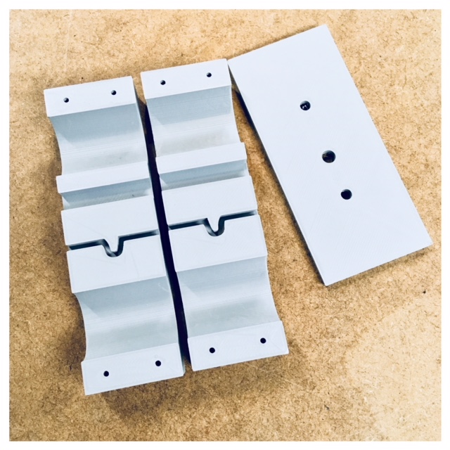
In the picture below I printed my part in white, so that you can get a feeling of which side (Left/right) I draw in Fusion.
The difference between the two sides is the holes for the screws. In my side, the holes inside are smaller than the end of the screw. This is because the screw has to cut its way into the PLA so that it will lock together better. In this way, both Anders and I got time to draw in Fusion 360 and create a piece together, individually.
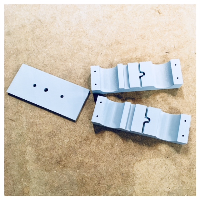

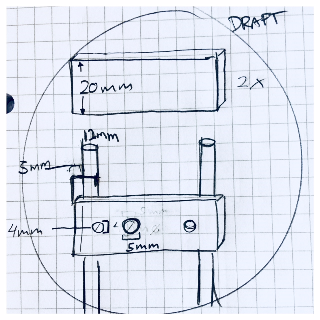
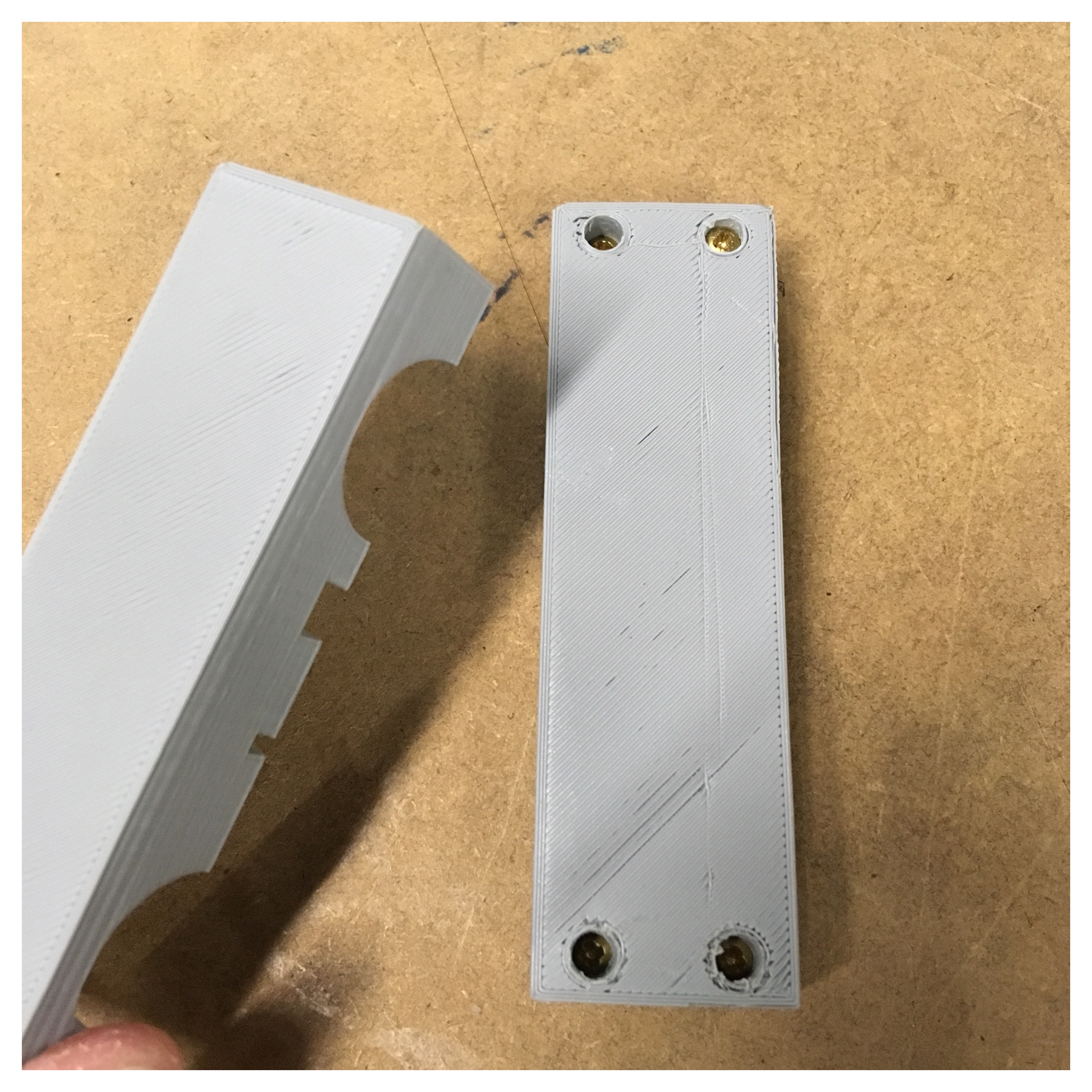
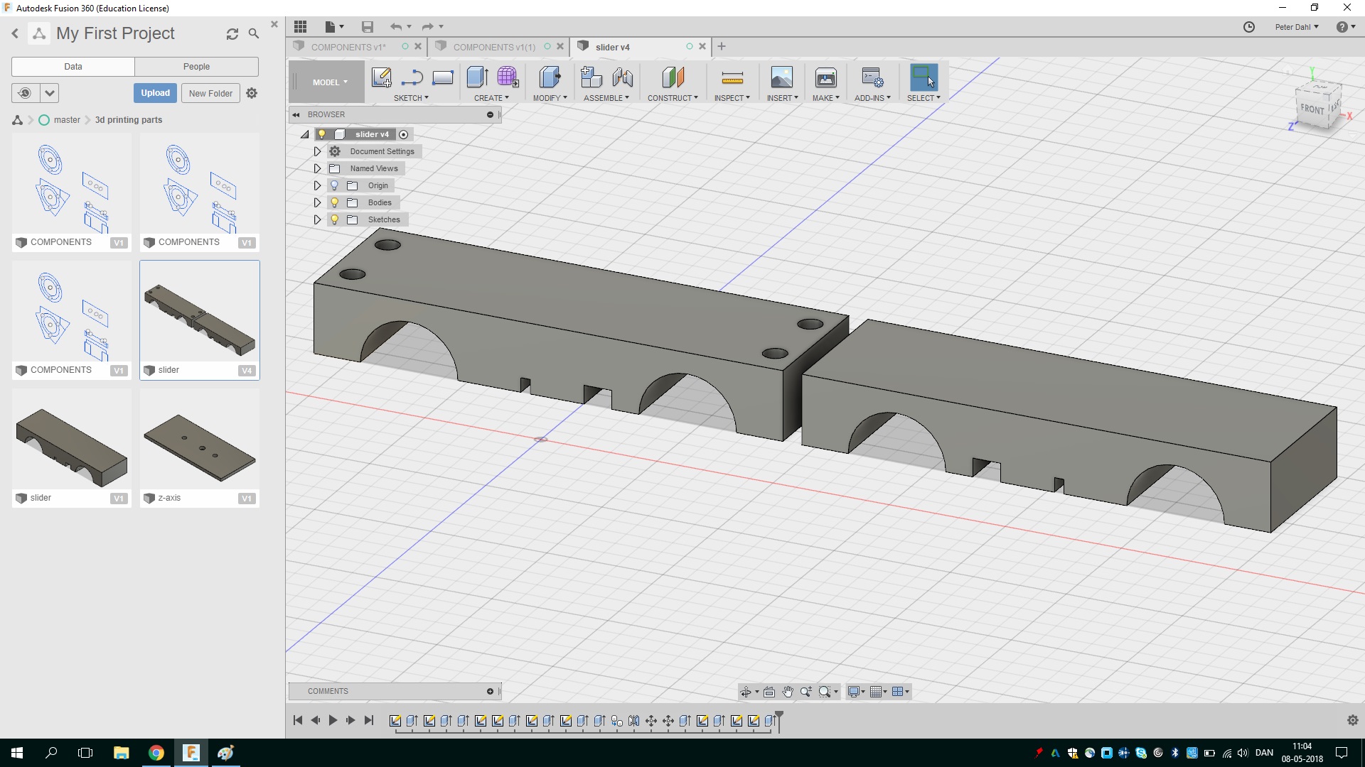
I made the design of the z-slider in two parts you have to screw together with 4 small brass screws. I made the holes on the backside part smaler than the actually screw, so that the screw has to cut itself through the PLA and locking the pieces toghter.
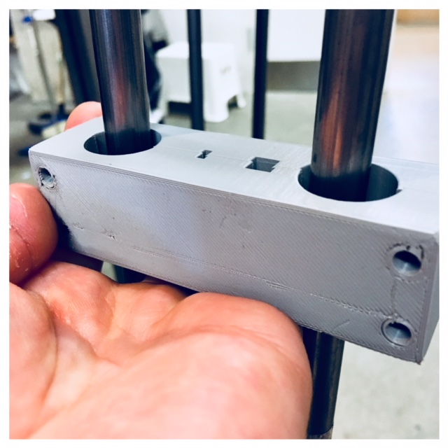
I had an issue I had to solve about the frame which gave some technical problems. This was about the holes in the top base. The holes where the belt is running through. The belt scratched against the MDF plate. I ended using a manually file and filing the hole a bit larger in order to move on. But of course the problem also had to be solved in the team. I therefore wrote to Claus that the hole should be slightly larger in the file, or perhaps rectangular, to avoid the rounded corners so that the belt won't scratch on the edges.
The communication part of working in a team is alfa omega also for improveing the machine. For example, when I find an area in my work that can be improved on the machine, it is important that the person(s) working with this part is well informed. So that changes will happen.
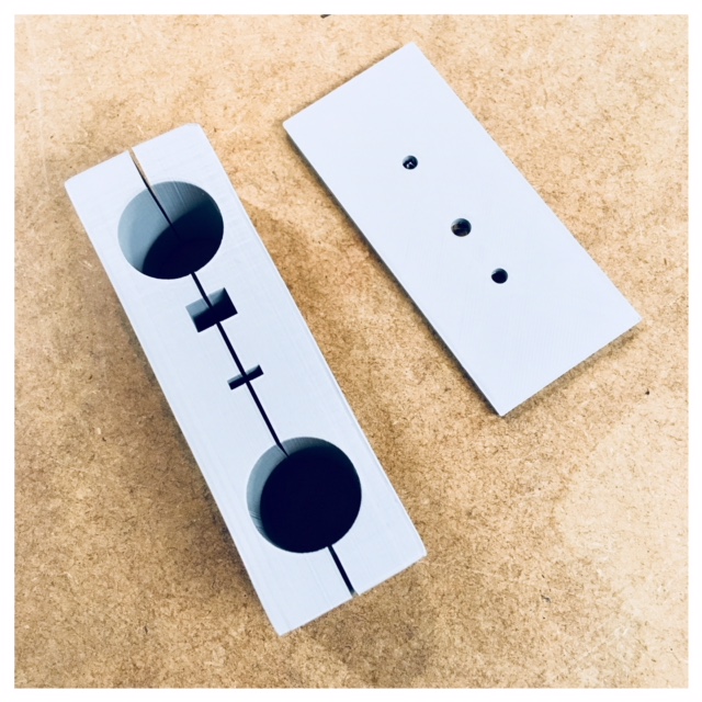
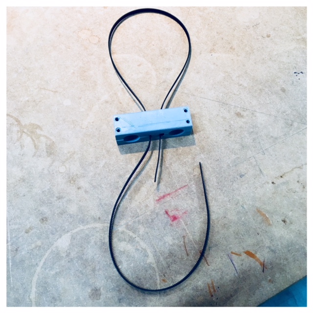
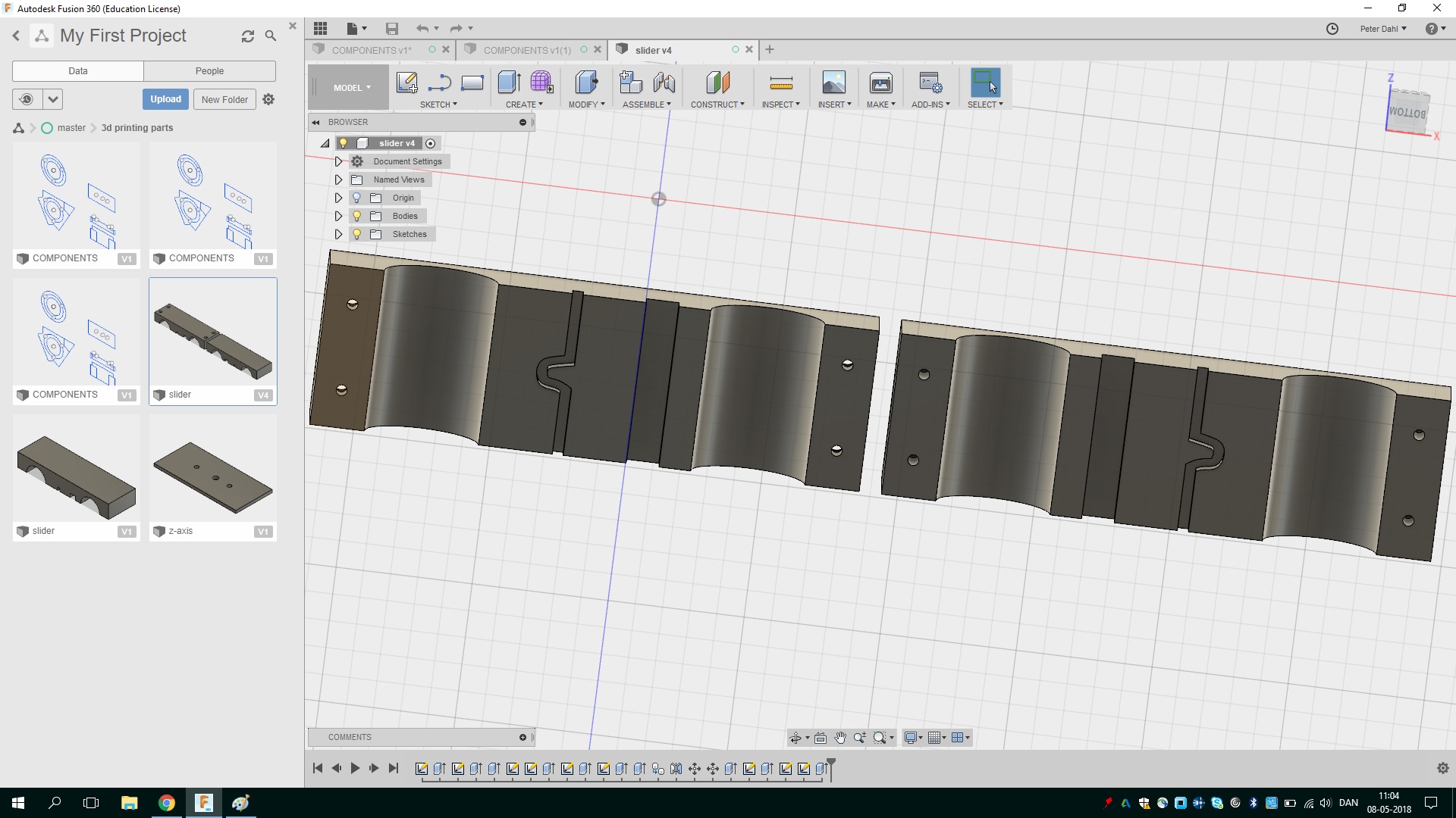
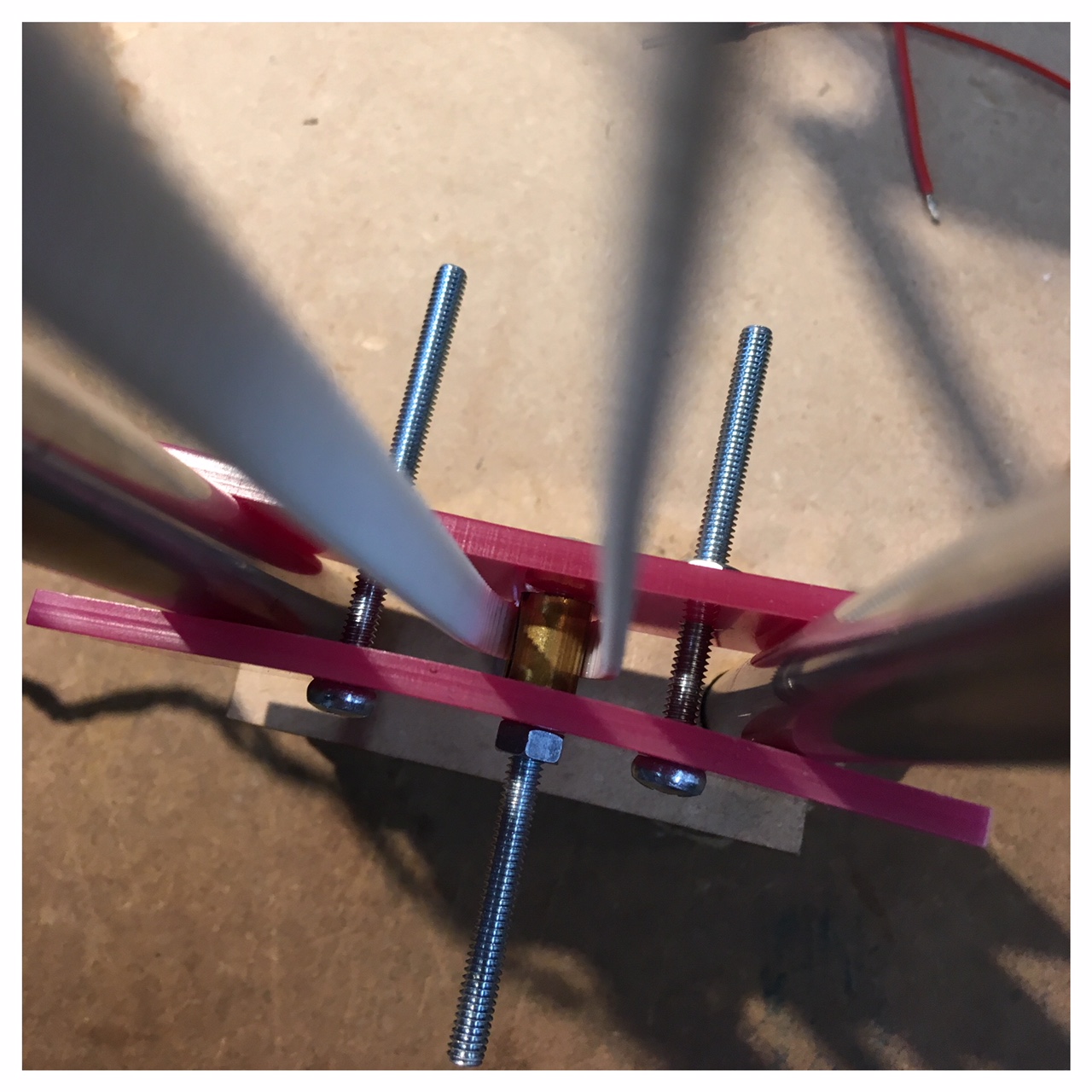
Locking the belts
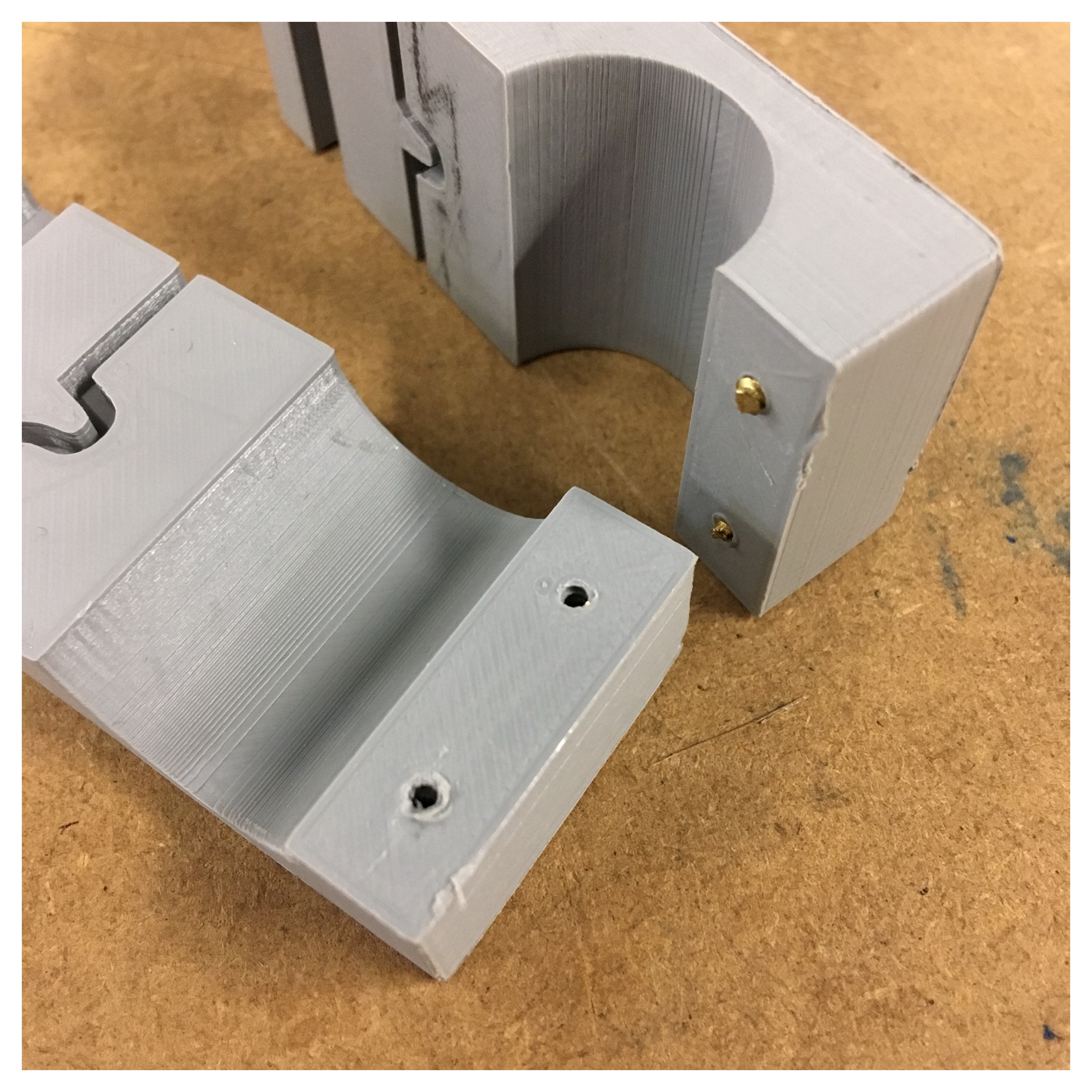
This curved line (as you can see on the pictures) is meant to lock the belt on one side and on the other side letting the belt slide freely. In this way, the 3D printed base will be pulled up and down.
Time issues with 3D printing
The speed of our Ultimaker 3D printers isn’t the fasted, and something that needs to be addressed in the group. Even small objects can take as long as an hour to print with conventional consumer-grade 3D printers, and it’s hard to know if a particular design will print correctly on a given system. That leads to waste and frustration as people fiddle with 3D models to compensate for the issues. I had to put in a very compact infill structure in the z-sliders because it had to be screwed togehter.
This, of course, meant that the print took longer. Each slider took 8 hours to print in PLA on the Ultimakers. So I startet the printer in the morning and finished one print during the work day. Subsequently, I could put more on before I went home. This slider/object printed over night and was ready the next morning. With this work flow I could make 2 sliders a day.
Drawing in Fusion 360
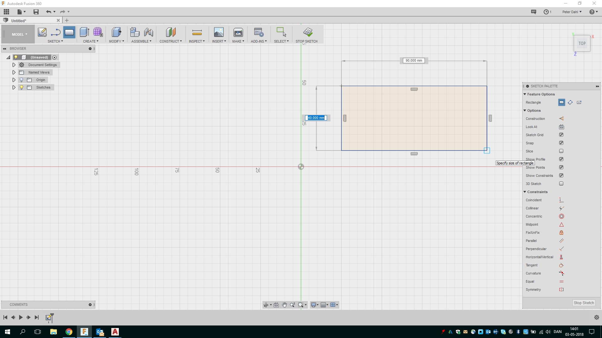
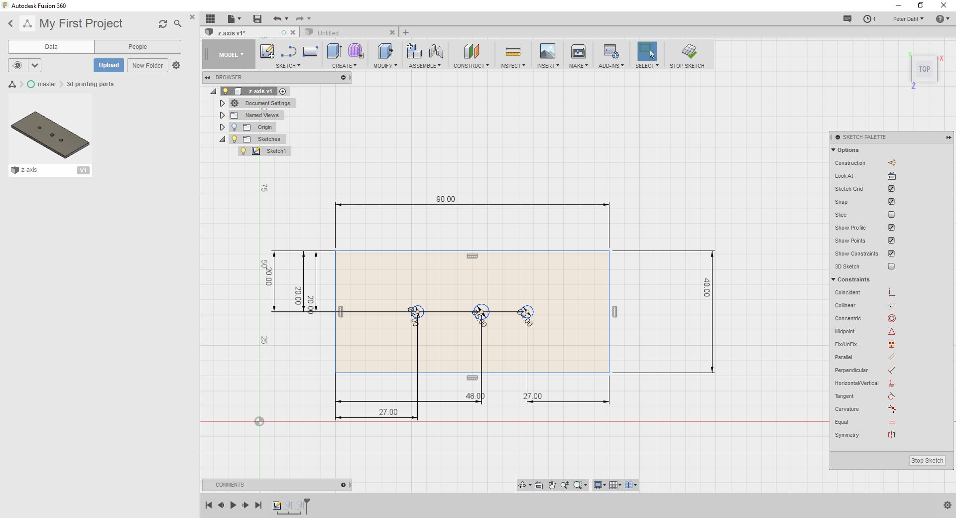
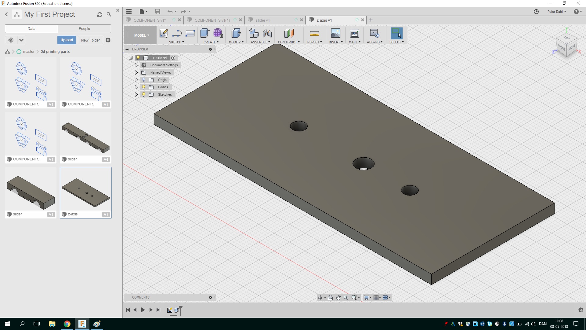
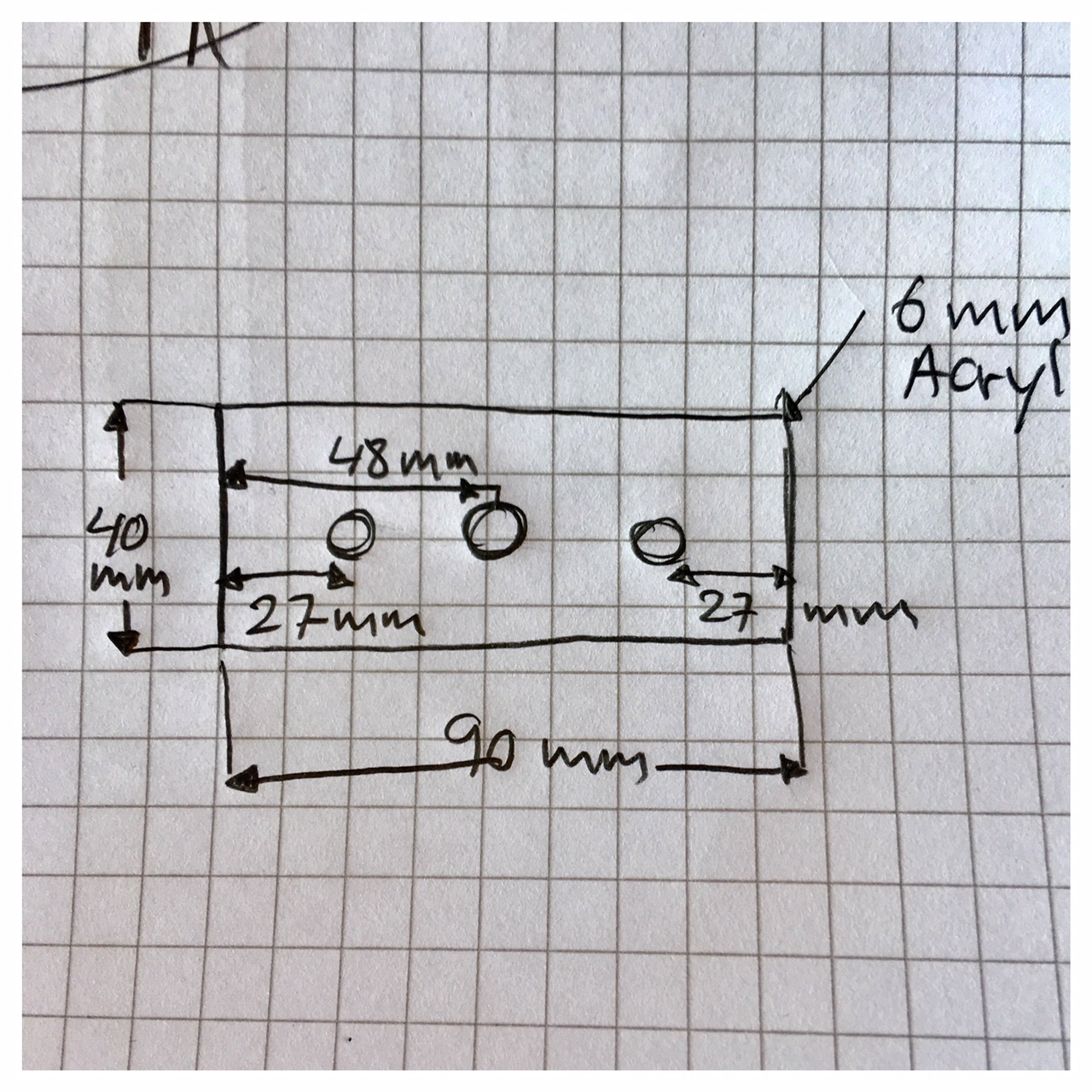
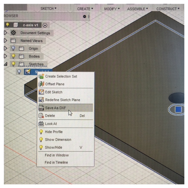
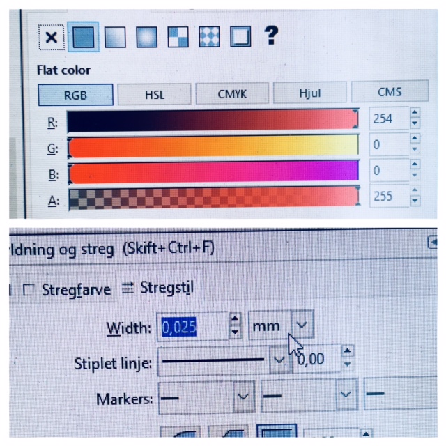
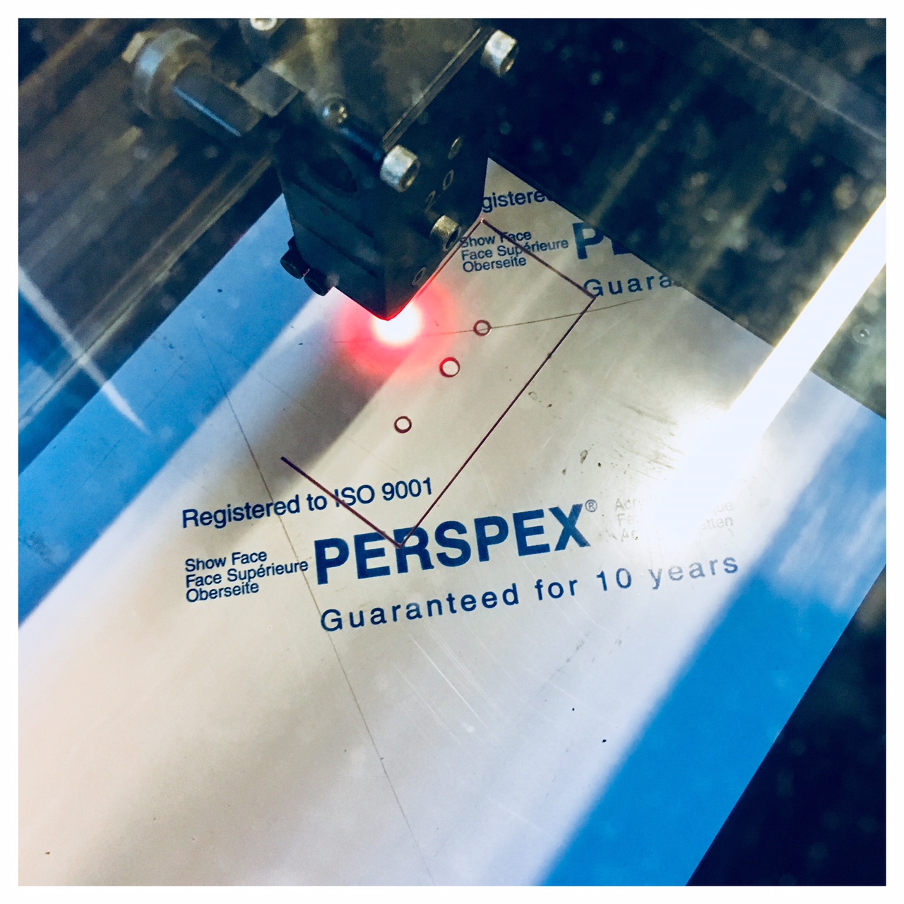
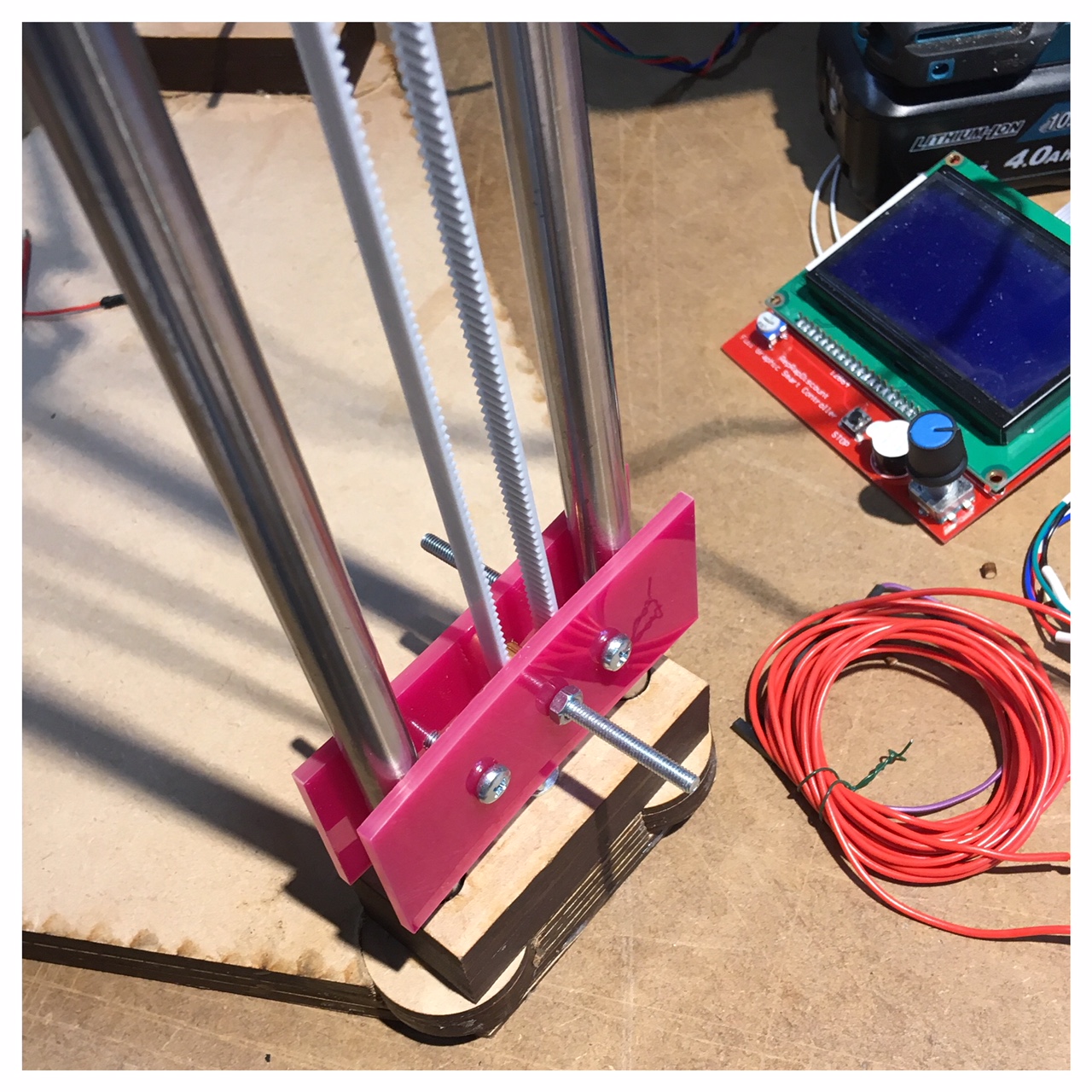
After talking with Bas Withagen this week we decided to cut the holders in the bottom of the Clay Printer in acrylic instead of 3D printing them in PLA. This is because the durability of the acrylic is stronger than the PLA. It is also due to the heat development that can arise from the constant movement of the toothed belt and the wheel, so that the PLA does not get heated and thus more fragile. I saved the file from Fusion 360 as a DXF-file by opening the sketch and making a right click on the folder icon. Here a menu will appear and make it possible to save as a DXF-file. Then I opened the DXF-file in InkScape to make the lines red (RGB 254) and width 0.025 so our Universal laser will cut through the acrylic sheet. From InkScape I saved the file as a PDF-file and laser cut the holders.
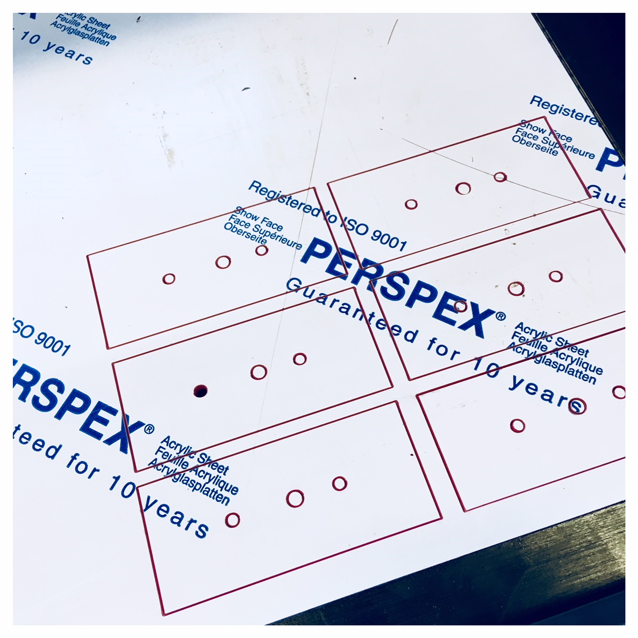
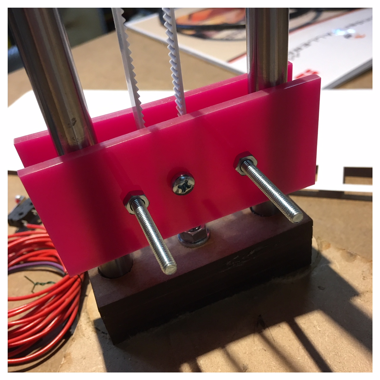
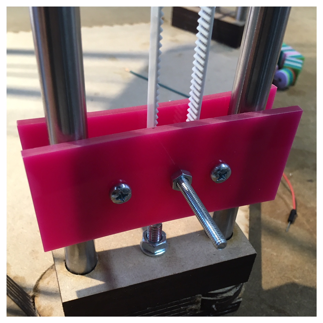
The bottom holders in pink acrylic, to make Carina happy.
Making The Machine Move by hand
To test the mechanical parts we have manually driven the delta printer by hand. It also provided an insight into how the machine comes out in the three corners of the printer bed.
To see how the whole machine was assembled and used, go to the groups project page fablabspinderihallerne"