Networking and Communications
Assignment
- The individual assignment for this week is to design and build a wired &/or wireless network connecting at least two processors
Files
Files for Bridge and Node made in Eagle and PNG-files
Building a wired network
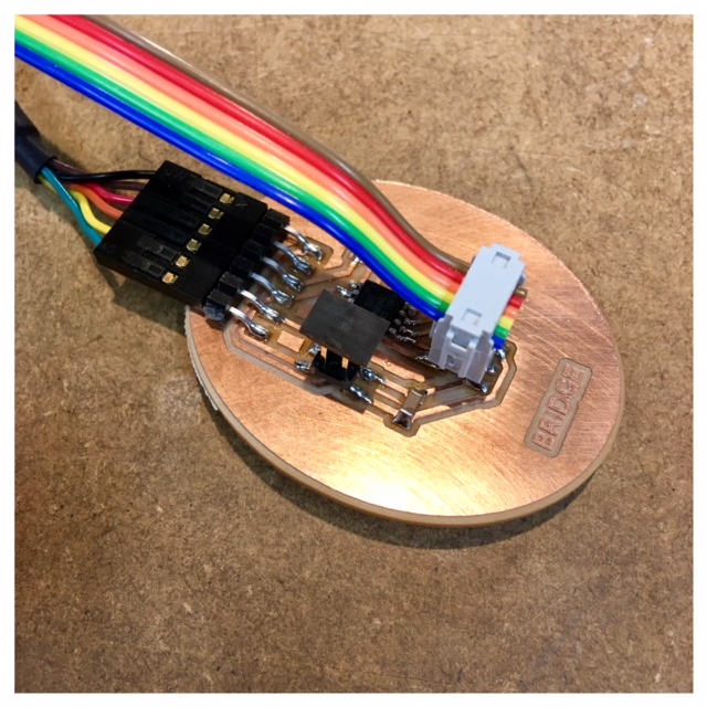
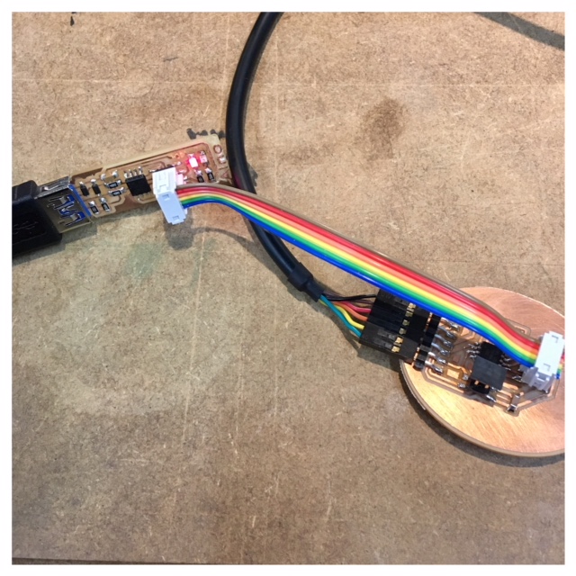
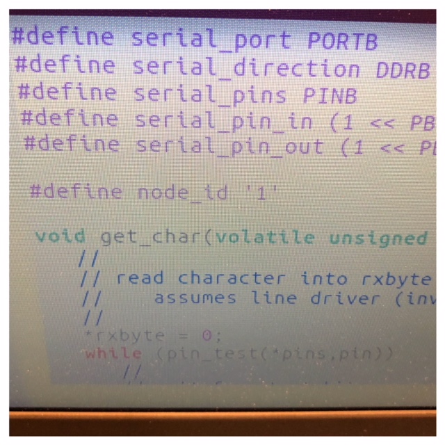
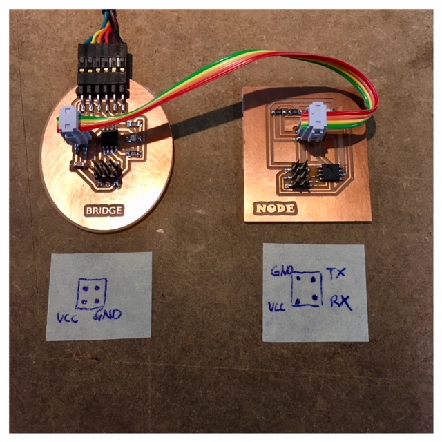
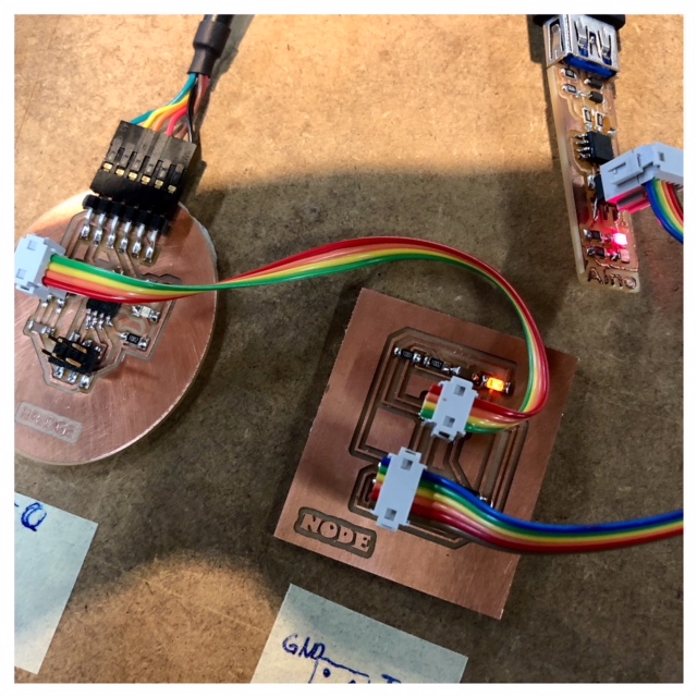
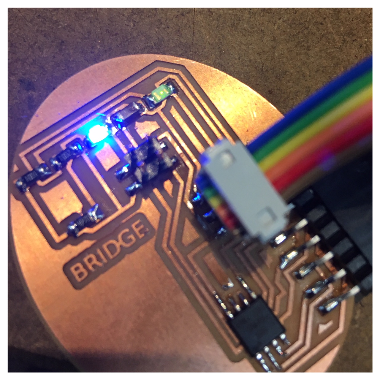
For this week's assignment, I decided to make a bridge board and a node board with an ATTiny45 to communicate by a wired network. As an entry for this assignment I referred to Neil's board and added a LED and a resistor. For designing the PCB, I followed the same procedure that I did in the past weeks using eagle and Fabmodules together with the Roland mill. The schematic and the board layout for the bridge- and note board are included at the top of the site under files.
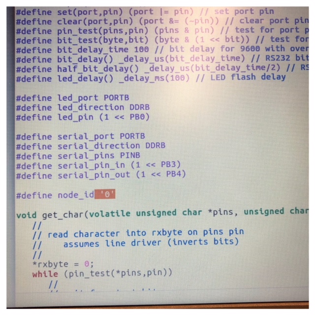
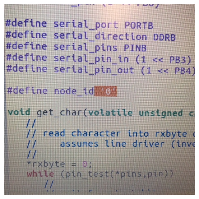
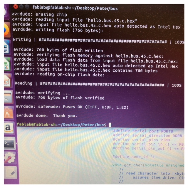
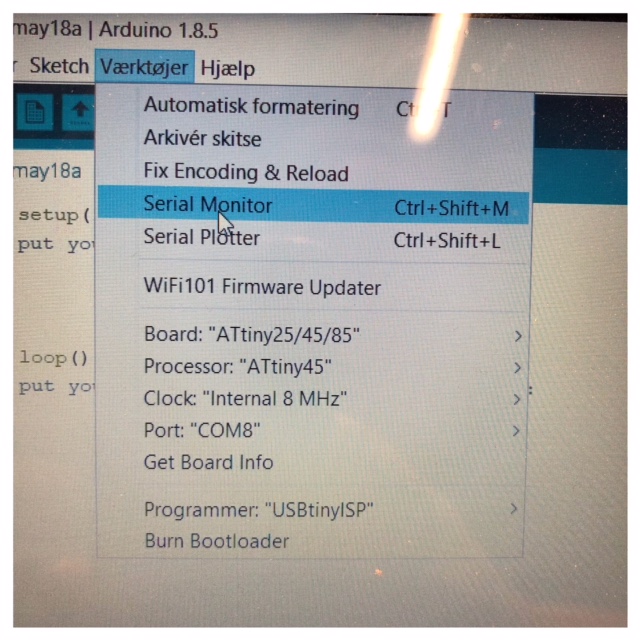
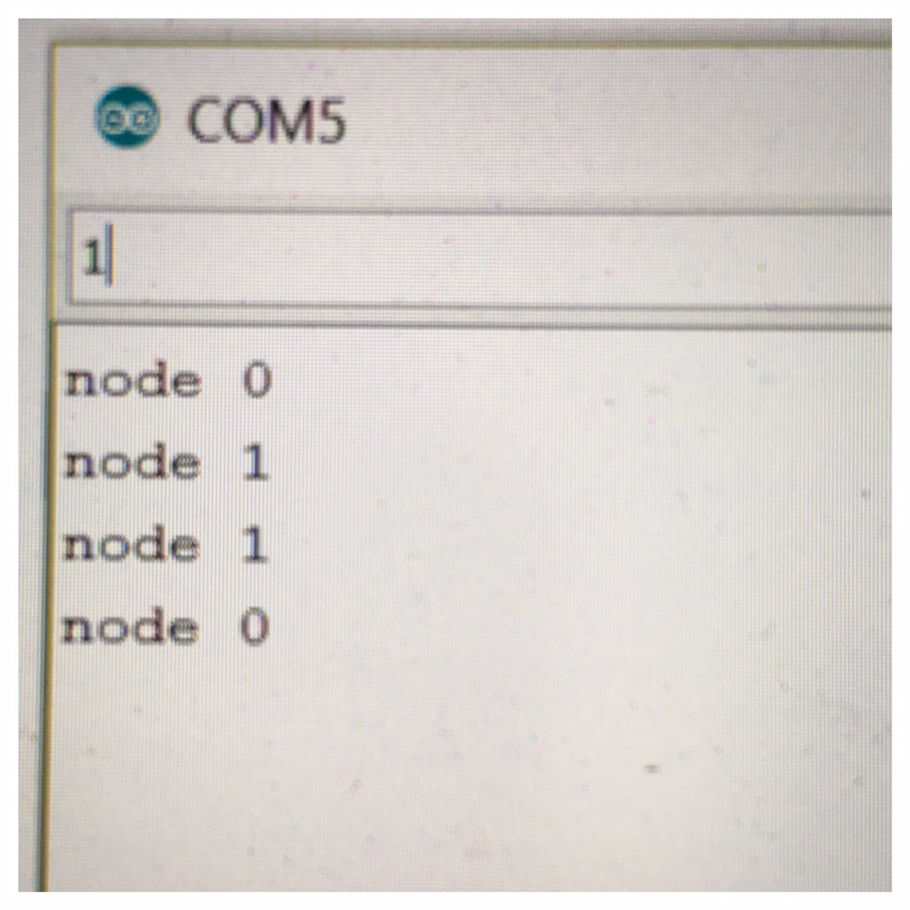
To burn bootloader on my two new boards I used my pc. After that I had to upload the make file and c code. Here I used the computer in the lab which runs Ubuntu. The first one I coded was the Neil example board. I named my bridge board "0" and the node "1" in the c code. When I uploaded the code I got an error about missing separators. I've seen this type of error several times now and it's about "wrong" spaces in the code that needs to be deleted. I think maybe they occur when you download the code and upload it to different programs. After a seerch for these wrong tabs and deleting them the code run perfect.
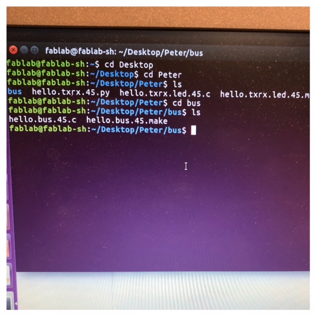
After saving the c-code in my folder on the labtop I had to find the right folder and Upload the c-code as yoy can see on the pictures.
Wireless network
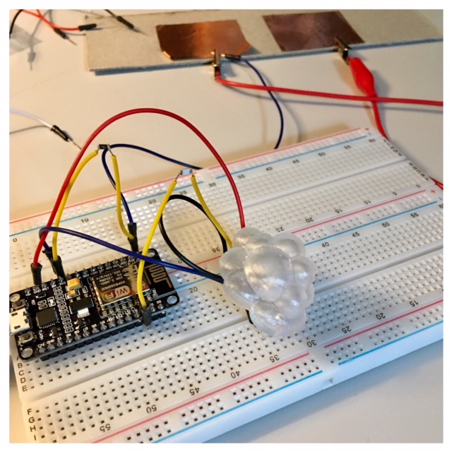
I have limited experience in programming but I need to get into working with a wireless connection in order to complete my final project. Because my Final Project is an IoT project where two microcontroller boards must communicate via Wi-Fi and turn on the LED's, I have chosen to look more into the wireless communication. I have seen different examples of people using a NodeMCU ESP-12e Development Board for these kind of projects. I will therefore start my week asignment with an atempt to get an ESP-12e NodeMCU to communicate with a server.
For testing I found out that you can get a little server space for free on io.adafruit.com. It's not a lot but a great help when you are testing IoT products where you sometimes need a little server space Adafruit free server space
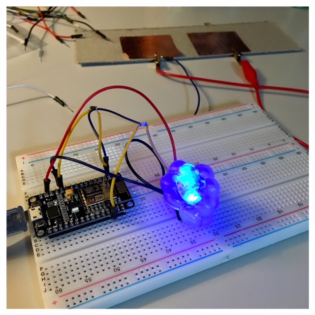
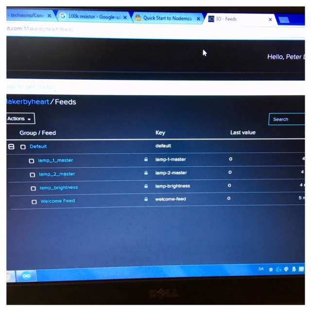
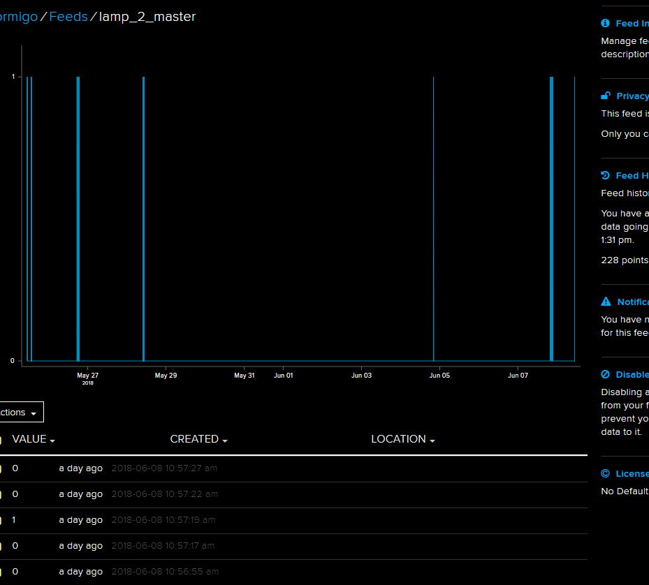
I added the board node MCU 1,0 (ESP-12e module) to my ArduinoIDE together with the Adafruit Libery (lib) and ran a code sample for Arduiono. I changed the server info and added the AIO key that I got from Adafruit in the script and it worked. As you can see on the pictures below I am now sampeling the lamp-1-master. There is one more lamp added the server lamp-2-master (that is going to be built by the kids in Mutku Maker Space in Finland). As for now the lamp is responding to the server as you can see by the number 1 and as you connect with the lamp the brightness will turn up and hopefully with time connect to the other lamp.
Click on the link below and watch the youtube video of my lamp. Sampling with an ESP-board.
Sampling lamp with an ESP-board
Communication between lamps
For working with my lamp-project network and communication week is essential for me. The wireless communication between my lamps via a server is an area to be investigated. I have found an exciting project I'm thinking of looking through. Check out the following link: Message Lamps
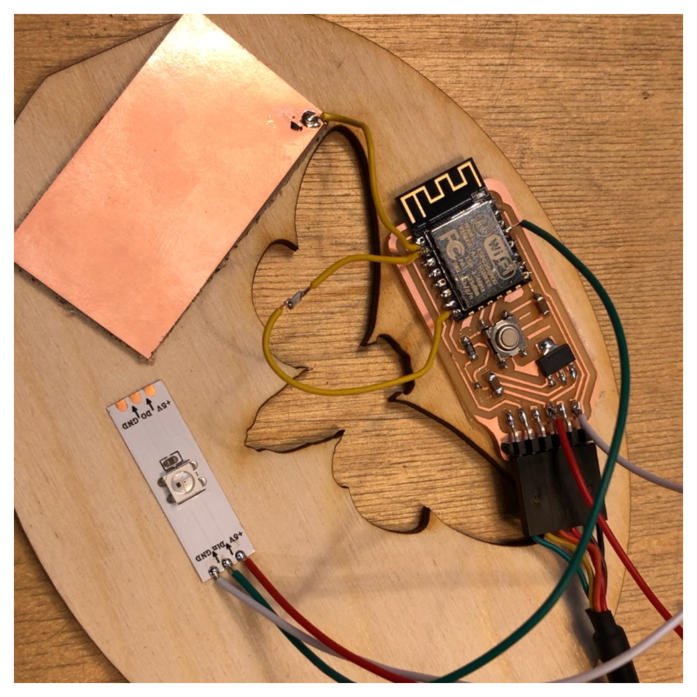
In the era of connected devices, I want to make a Wi-Fi enabled touch light that connects people. I truly loved this product as in this generation of smart phone where each and every thing, every activity is taken over by our smart phone, this product will let you share a feeling or an atmosphere.
In this project I like to have 2 lamps which has inbuilt WiFi to connect to AdaFruit server via the internet. Then by touch my lamp should make the LED Glow on my device. After a few seconds, another LED Lamp which is connected by the server-space will also start glowing with the same intensity. The longer I touch the lamp, the brighter the light will be. The code uploaded on these boards is bit complicated for me to explain and actually also understand with my background og education (primary school teacher). I will try my best to explain the project as the process develops.
So remembering Neil's talk about standing on the shoulders of giants, I reused parts of the code as in the "Message Lamps" (check the link above for his code and manual).
I set up an account on io.adafruit.com for using their server-space for this project. You can get 30 days for free, then thay clean up the space wiping away your work. I made an extra folder on my laptop, so that I just could recreate the work, getting 30 new days. I think it's nice to use a free service for developing projects.
Workflows used in network design and construction
To start a place when talking about workflows in constructing a network design and make communication between two micorcontrollers through wi-fi I will start with trying to explain my code and the connection between my lamps.
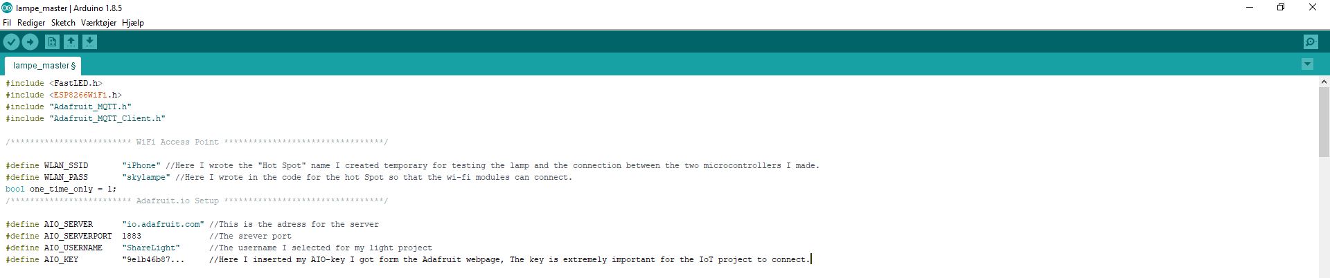
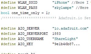
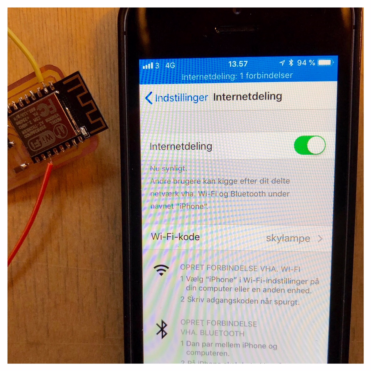
In the line where I define WLAN_SSID I wrote in the name of my temporary "Hot Spot": "iPhone" (see the above picture) for testing the lamp and the connection between the two microcontrollers I made. In the next line of my "masterlamp code" define WLAN_PASS, I wrote in the password for the Hot Spot so that the wi-fi modules could connect to the internet. In this case the password was "skylampe".
Then there are four lines about connection with the adafruit server space and direction to my little server project I call "ShareLight". First line of code is: #define AIO_SERVER "io.adafruit.com". This is the adress or direction for the server at adafruit.io. Then a deffinition of the serverport: #define AIO_SERVERPORT 1883. After this is done I had to write in my AIO username, in this case" ShareLight: #define AIO_USERNAME "ShareLight". The username I selected for my light project.
At last I wrote in my AIO-key I got generated form the Adafruit webpage. The key is extremely important for the IoT project to connect. #define AIO_KEY "9e1b46b87...
Networking protocols
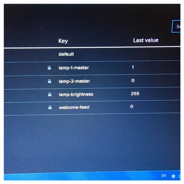
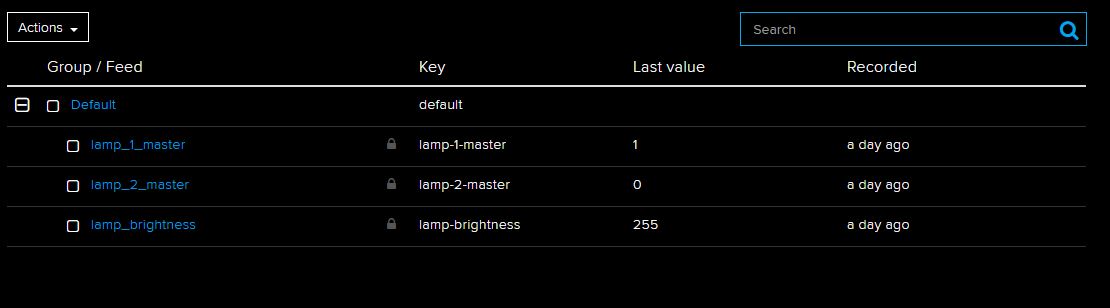
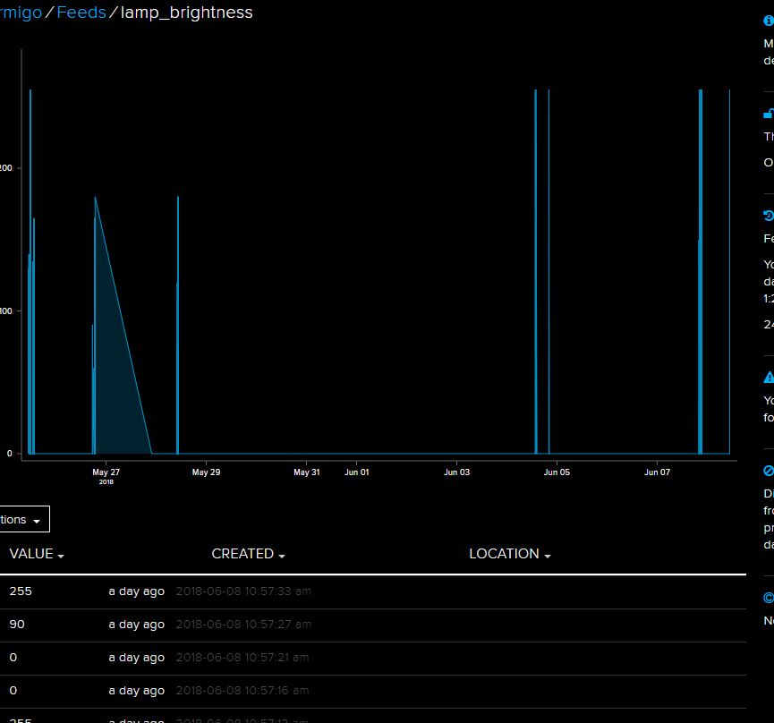
Under the server webpage I can monitor different feeds or date coming in and out in the network between the lamps or the boards I made. I can as an example monitor the brightness level I defined in the code. The brightnes can go up to a value of 255 in brightnes, but that all depends on how long you touch the touchpad of the lamp. In the first picture you can see that there is an interaction with lamp1 and the brightness value reaches the value of 255.
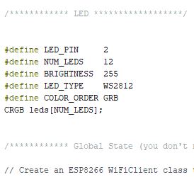
To give an example from the code about this brightness level please see the above pictures. First I define the LED's I am using. The communication from the microcontroller to the LED's goes from the digital port LED_PIN 2. In the second line I define the number of LED's I work with (In this case 12). Then I define the brightness level to 255 (Witch is a bright amount of light).
Then I define the LED's I worke with. For this project I choose the WS2812b witch is adressable LED's where I can influence the color of the project. For the color decistion I then have to define the order of the RGB (RED, GREEN & BLUE) in this case the order of mt WS2812b are G, R, B.
It also keeps a protocol under feeds where I can monitor the date of the interaction. I put in a few different pictures. One from lamp1, lamp 2 and one for the brightness.
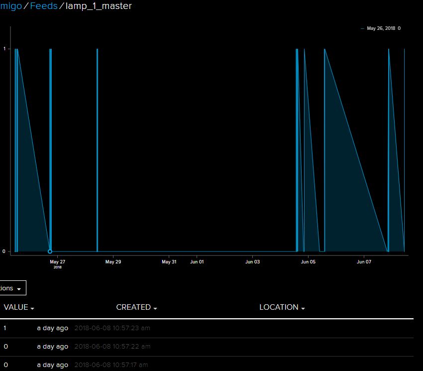
In this last picture you can see the different values of brightness coming in to the server. You can see that not all the values are reaching the brightness value of 255, some are nearer to 90 or 100.
The ESP and network protocols
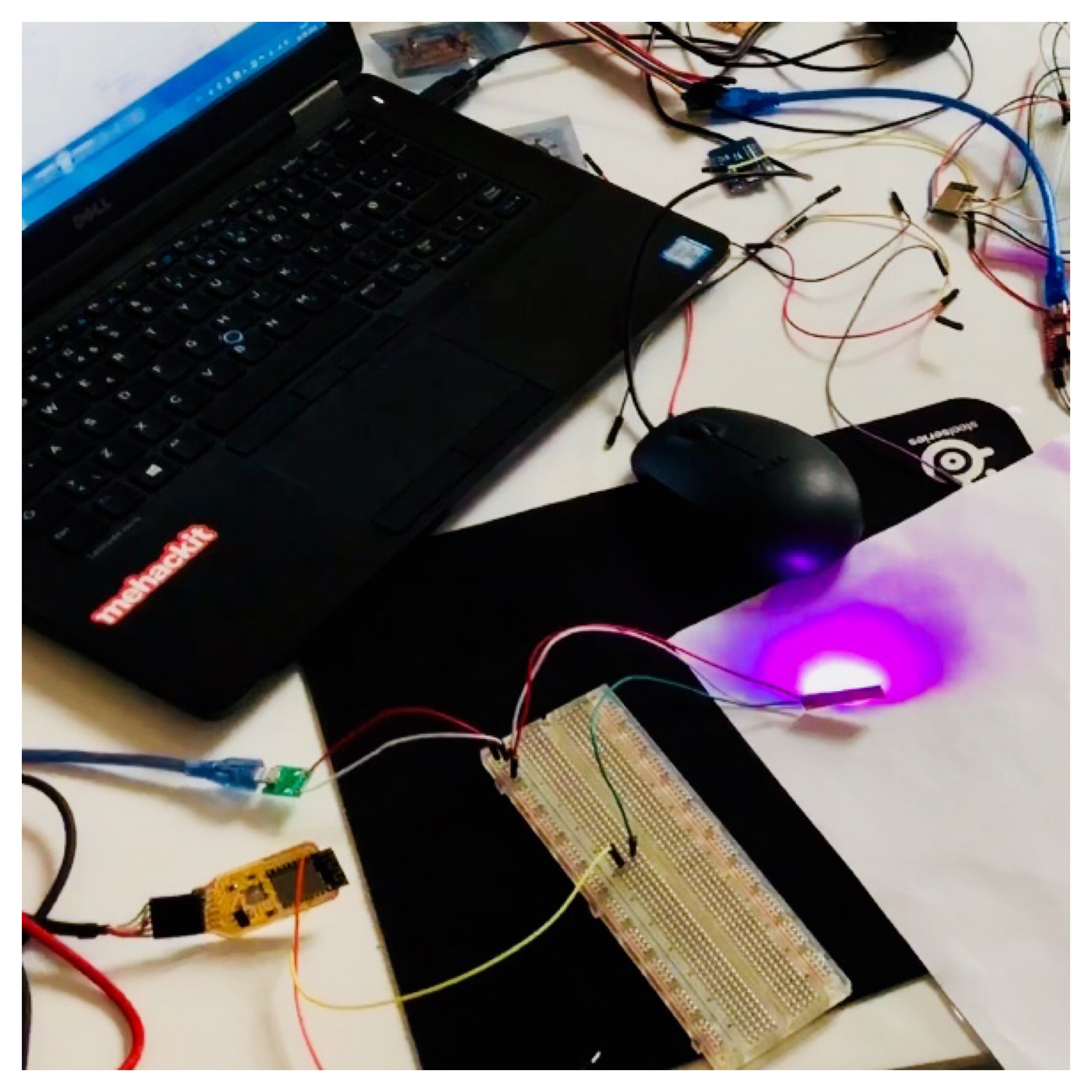
Where should I starte here. Hmm the ESP is right now a little like the story about Ahab's quest for the White Hvale. Right now I am really struggeling with getting this to work. I made a quite big range of different ESP-boards and modules and for everyday I think I get a step closer. I managed to flash my code on one of the ESP12e-modules after a lot of trial and error and it connetcs to my iPhones shared internet or hotspot.
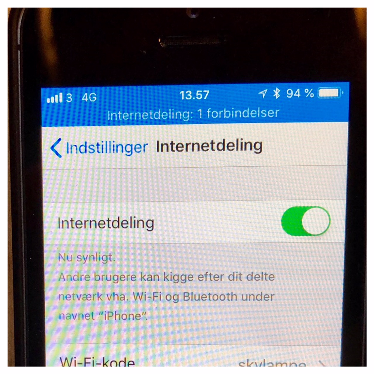
As you can see on the picture below the ESP is connecting to my iPhones shared internet. In the code I managed to flash to the ESP12e it says that it should connect to the Internet called "iPhone" with the password "skylampe". In the upperpart of the picture of the iPhone is says in danish: "Internet sharring 1 connection". So it definitely connects to my phone.
A little breakthrough
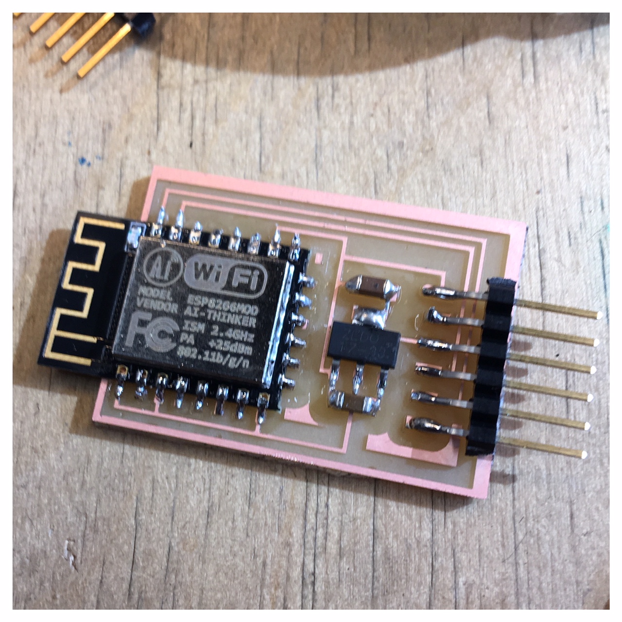
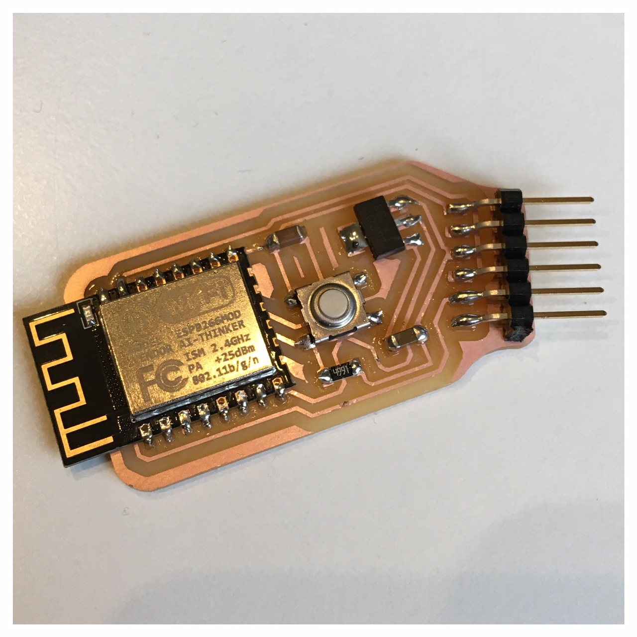
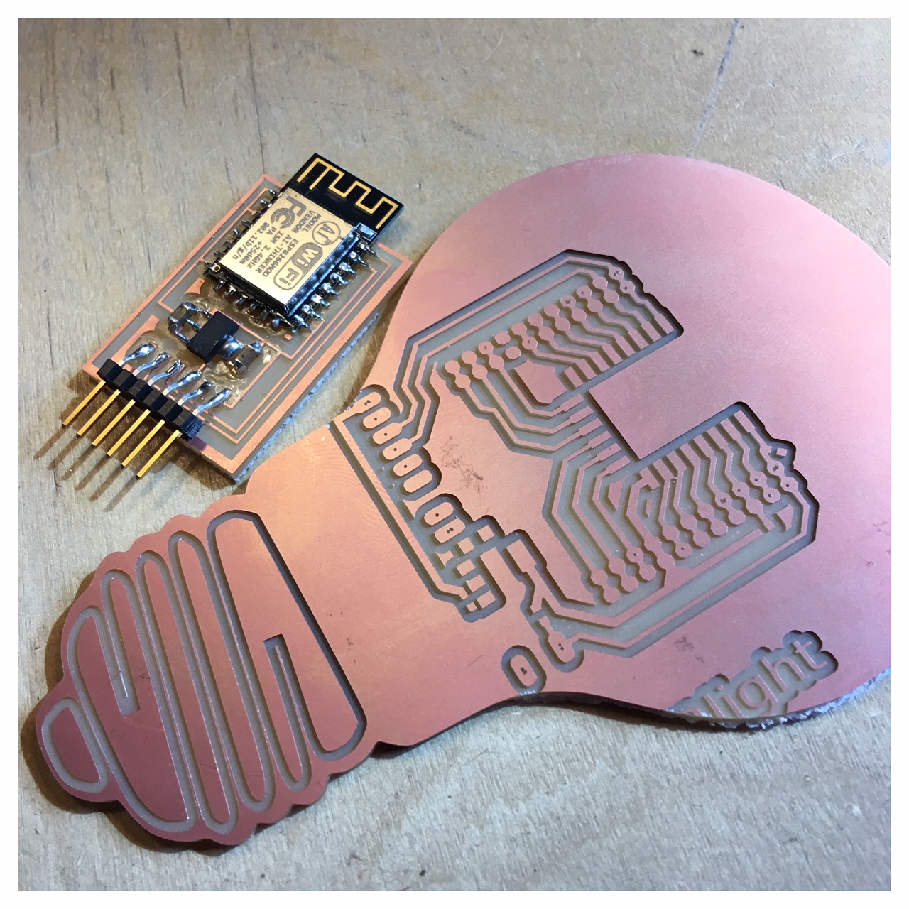
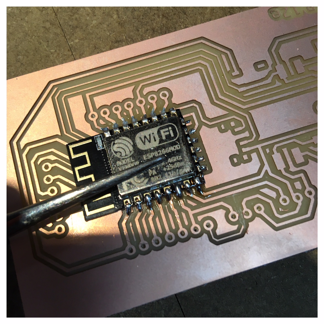
Then a little breakthrough came. I had made a little board with an esp12e on similar to Sander Van Vliet who had made a redrawing of Neil's hello.ESP8266-12E.ftdi board hello.ESP8266-12E.ftdi. I corrected a few small errors that Sander himself describes in his student site under final project. With this board I had a succes with flashing my code to the esp12e.
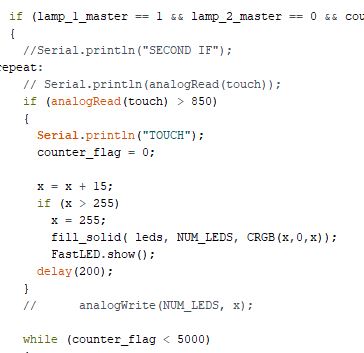
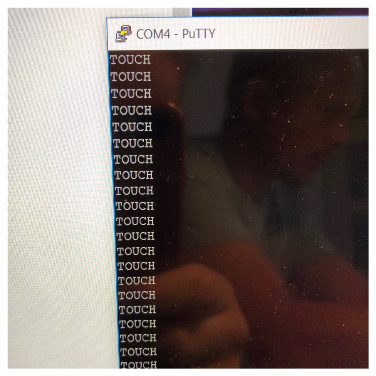
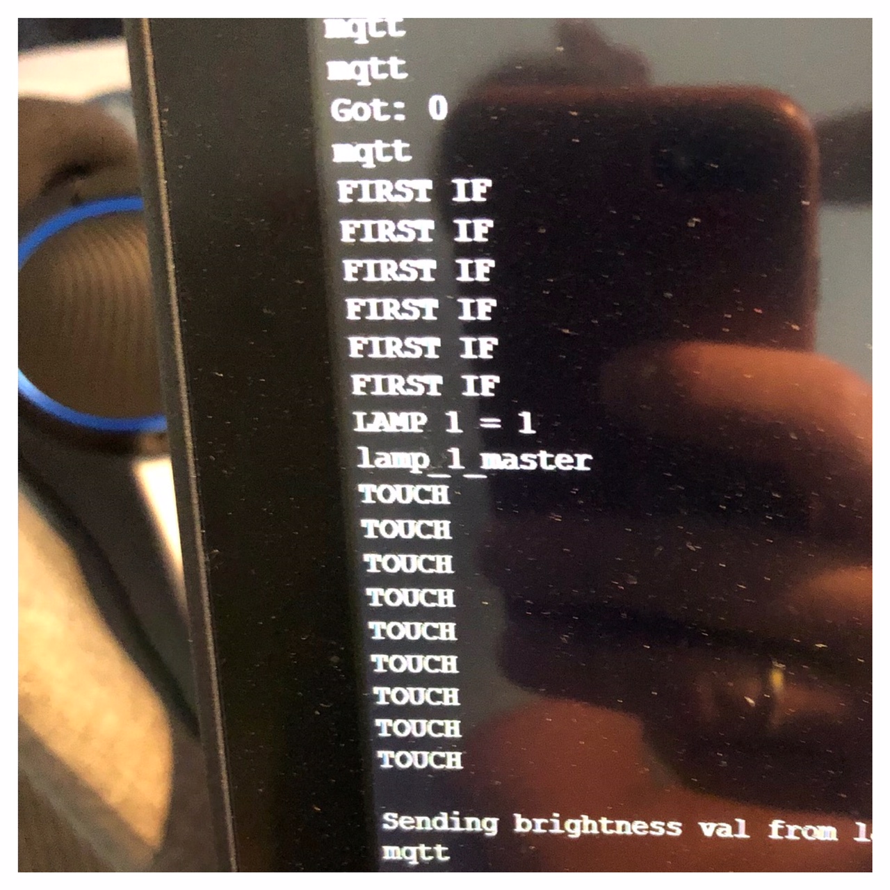
Then I downloaded this software called PuTTY, where I could monitor signals coming into my computer and which port it's using and follow the protocols of the network. I could see when I touched pin 2 (the ADC, TOUT) on my esp I got a "TOUCH" signal comming into my computer and "FIRST IF, LAMP 1=1, LAMP_1_master, TOUCH, TOUCH..." So it was actually performing my code.
Now the board connects with the esp to the server using the key from Adafruit I wrote into the code and the two esp are connected through the wi-fi hotspot and the serverspace I called "ShareLight".