Input Devices
Assignment
- Measure something: add a sensor to a microcontroller board that you have designed and read it.
Files
Step response
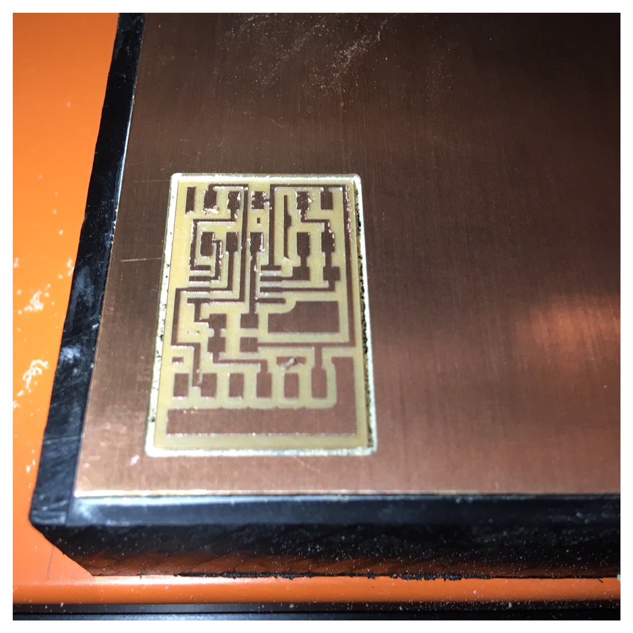
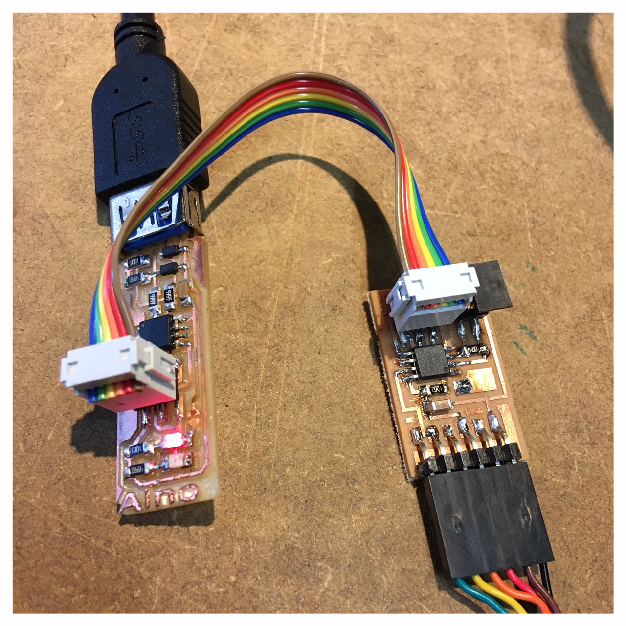
This week I made a capacitive touchpad with an ATTiny45 micro controller which measures input voltage on a copper pad using step response. My thoughts about this little capacitive touchpad is that the copper plate should be shaped like a cloud and go down through my concrete base and act as the button of my lamp.
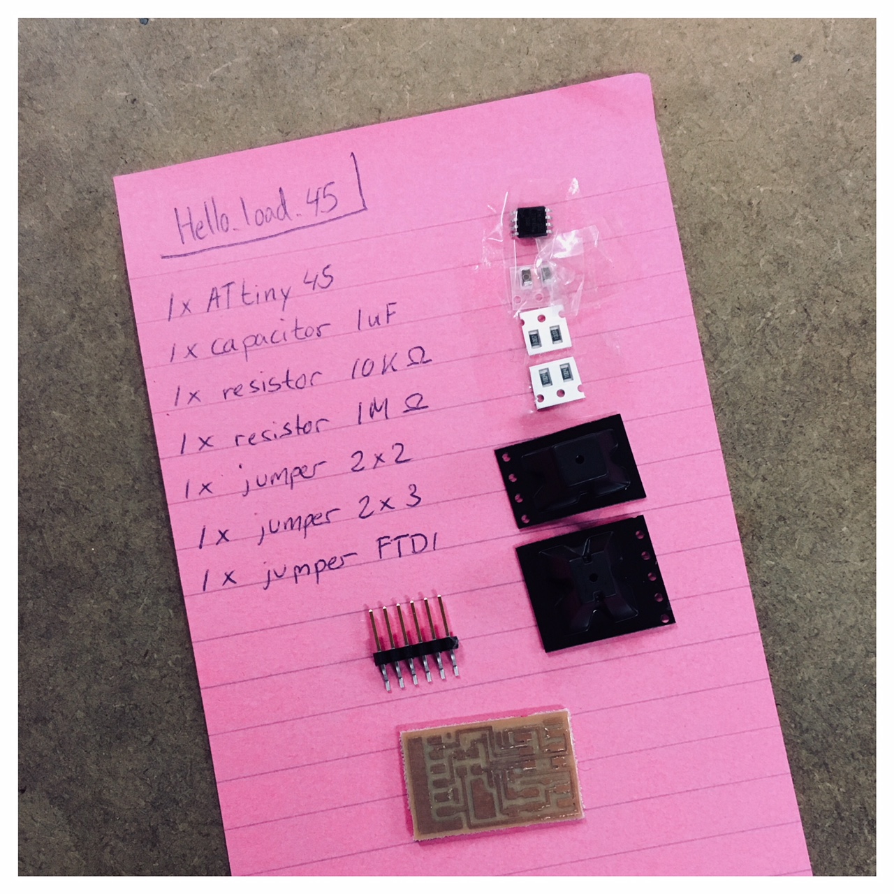
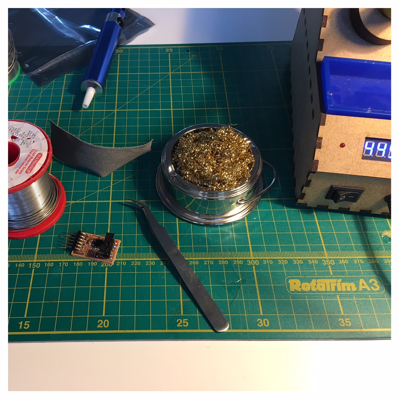
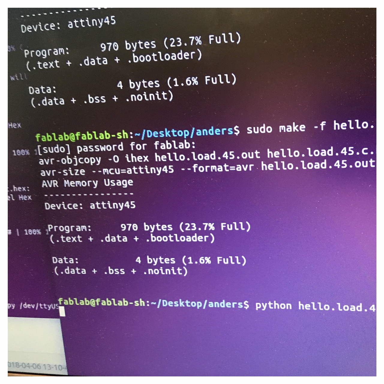
In an effort to learn and understand step response and its precision I milled Neil's demo step response circuit and ran it with the three code parts he provided (the hello.load.45.c, the makefile and the hello.load.45.py). Unfortunately the first time I programmed the micro controller I ran into a series of different problems. Everything from a plug that was not properly fixed to errors in my code but eventually managed to measure input.

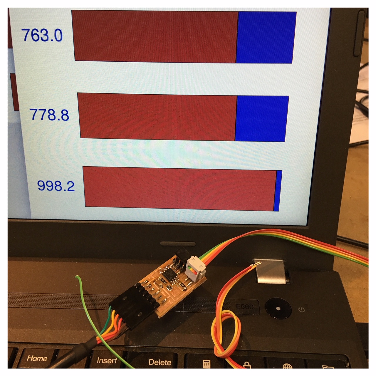
Watch the video below of my step response experience.
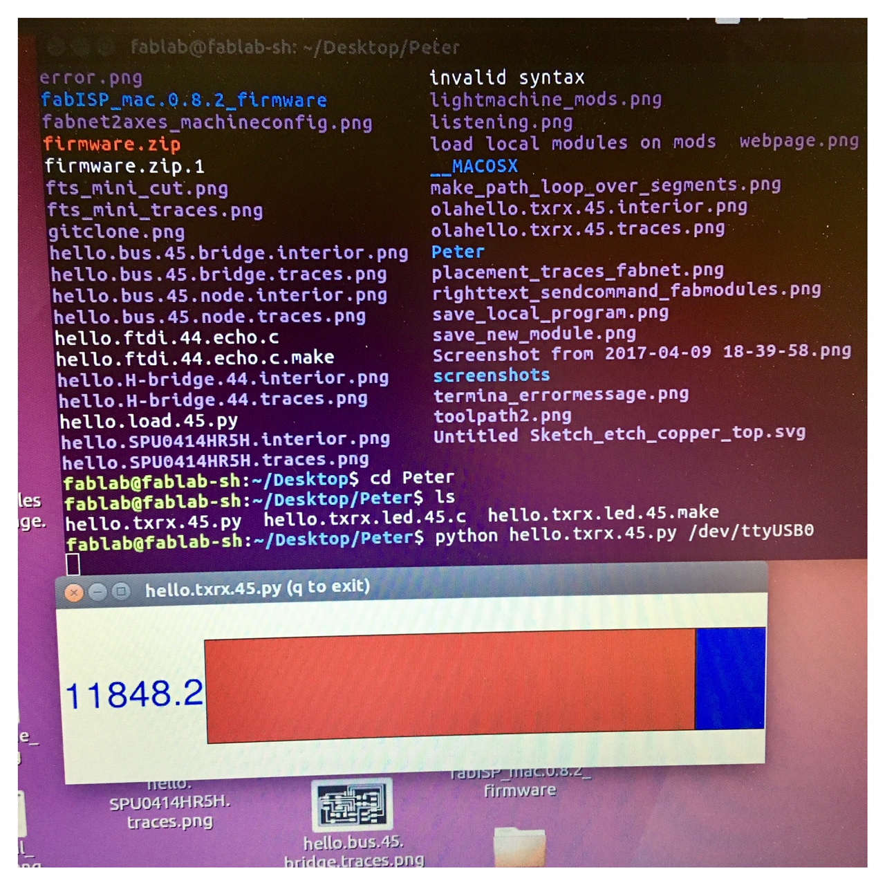
hello.txrx.45
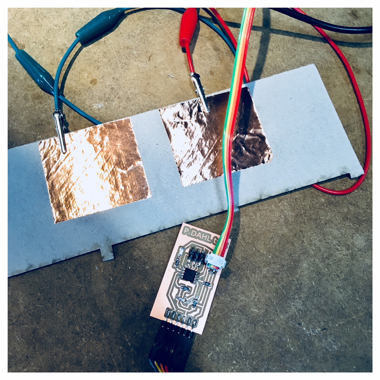
After this weeks regional review I talked with Bas Withagen. He recomended me to look more into the transmit-receive part of step response to get a stronger signal for my lamp in the final project. I learned from him that with the touch pad that I made with hello.load.45 my lamp would light up more easily if there is a lot going on in the room. In other words it would be more susceptible to movements and shakes. With the hello.txrx.45 I could make a more stable lamp, that would have a stronger input signal.
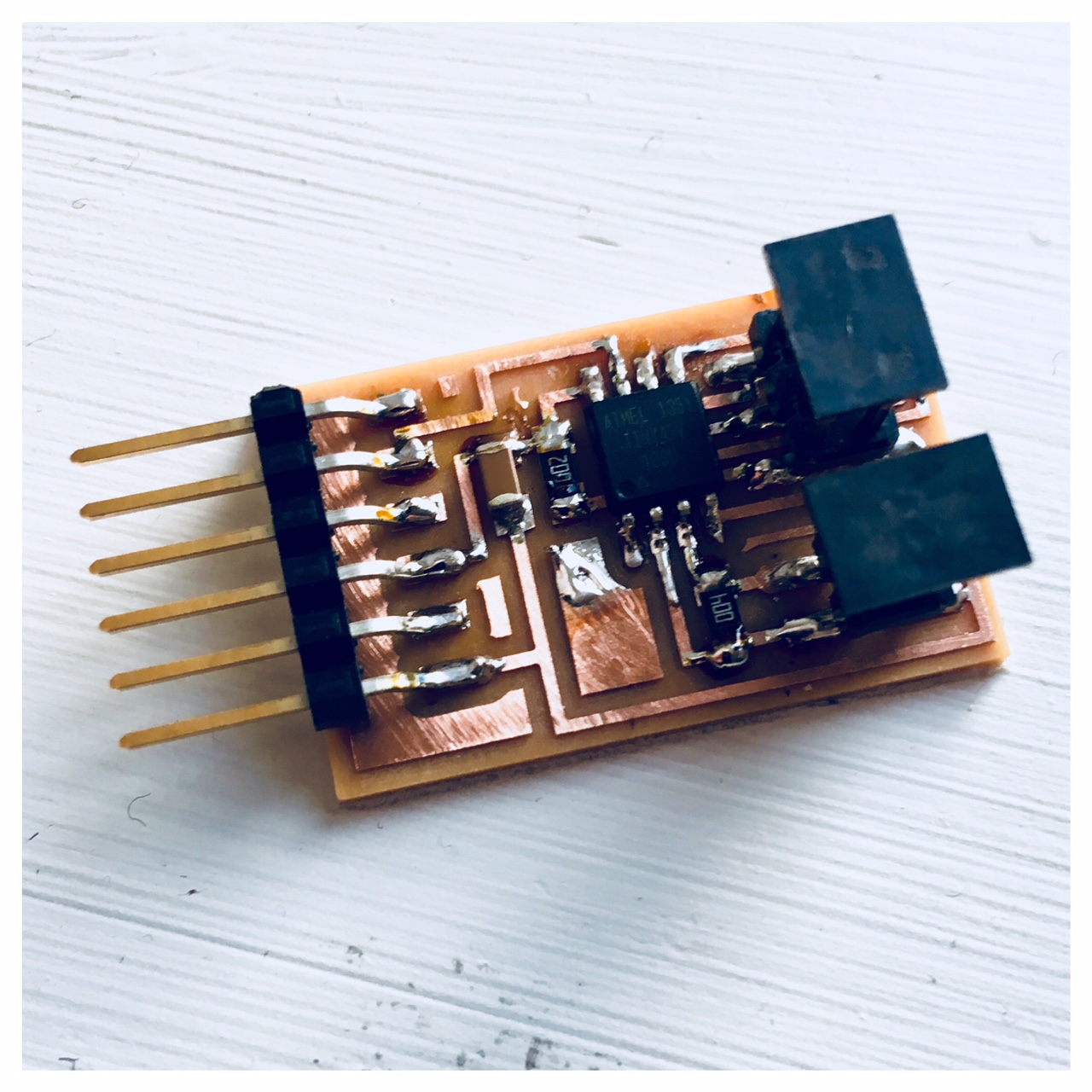
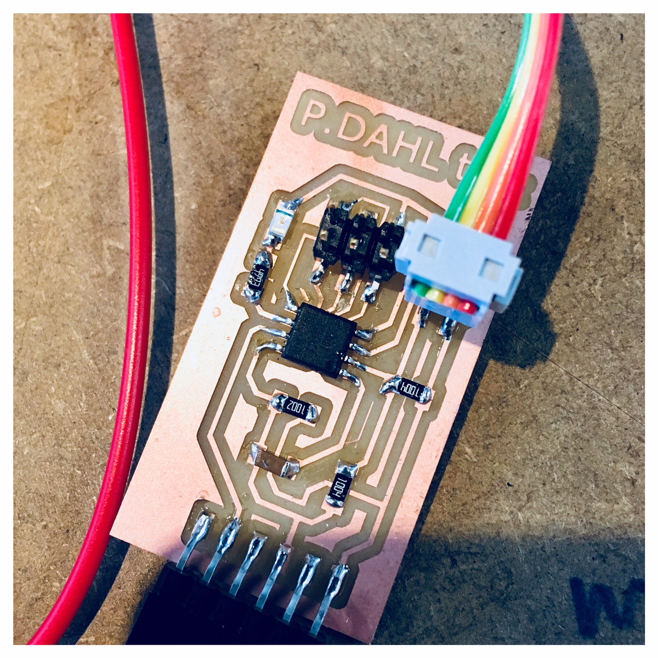
The hello.txrx.45 board uses an ATtiny45 8-pin microcontroller, 3 resistors, 1 capacitor, and connectors. I think this is the right board for my lamp and with some small modification I will try to fit in an LED to sample my output ideas as well and also add a new feature. However, the ATtiny45 microcontroller has 8 pins so it has a more limited number of I/O pins and all were in use. But I read that Neil once said that the pins used for the In System Programmer (ISP) could be used for other purposes when the ISP was not connected. In the schematics I can see that the ATtiny45 pins PB0 and PB1 are only used for In System Programmer (ISP) MISO and MOSI connections. I tried to read through the data sheet for the ATtiny45 and decided to try to connect an LED and a resistor to the MISO and GND creating a extra trace in eagle.


Again I used EagleCAD to draw up a new schematic for the transmit-receive step response circuit (txrx) and added a resistor and an LED for sampling my output. If this works for me and I can get the LED to light up I think I will pursue this idea for my LED output in the final week trying to create an LED-board to connect to my txrx.

After working with Eagle for my schematic and board I exported my board as an PNG-file with a 1000 PPI and imported it to Inkscape to create the frame (cut out) and adding my name and the board information (txrx) as well.
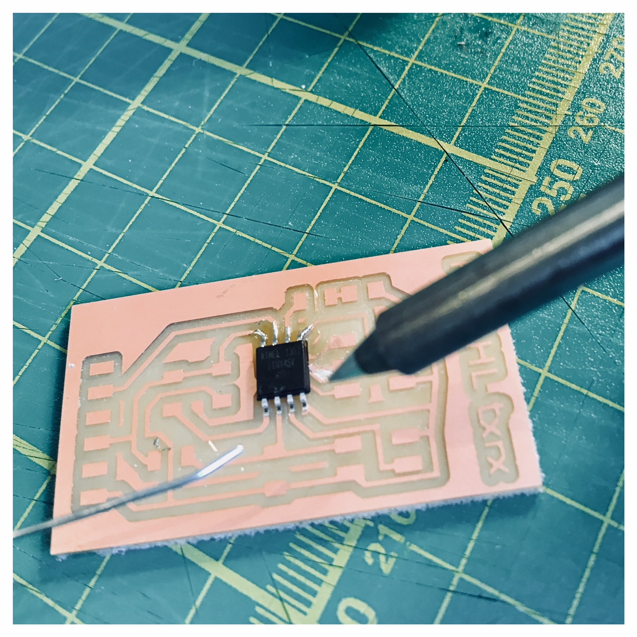
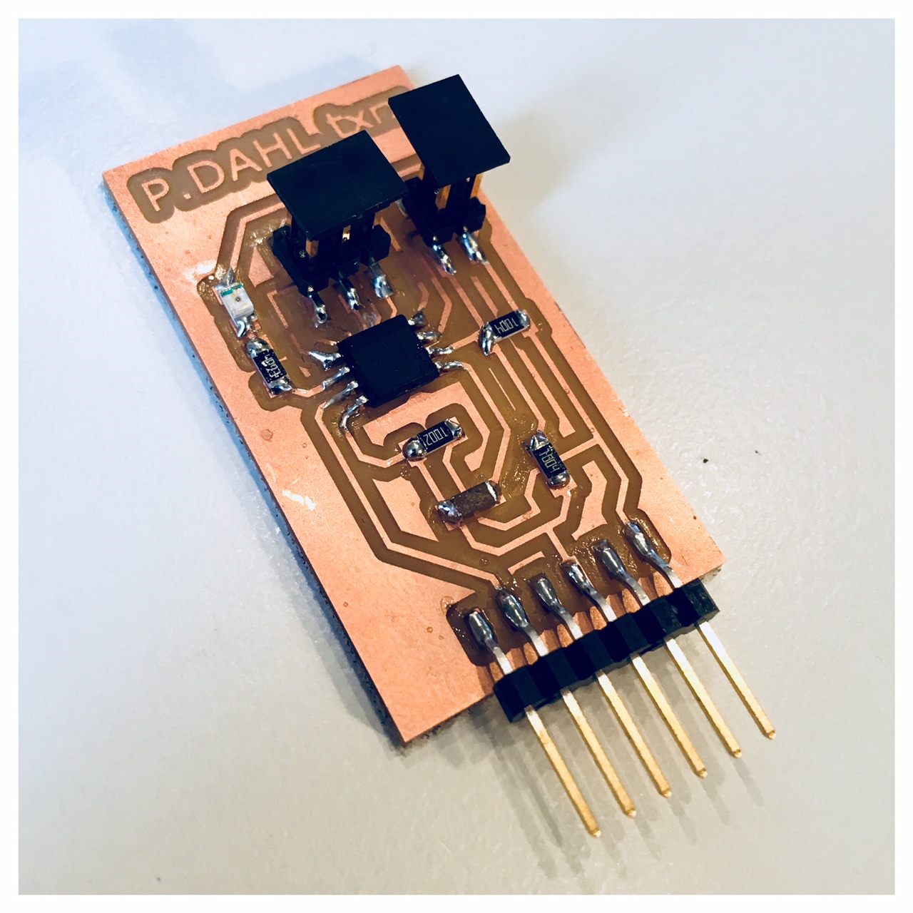
I reallly love the milling proces on the Roland SRM20. It's so amazing that you can CNC your own PCB in a relatively short amount of time. I think the milling went great and I got a pretty nice PCB so now the time comes for the progarmming of the txrx with an LED included.

Click on the link below and watch the youtube video of my transmit-receive experience.