Share Light
Project development
Files
LightBoard Eagle .sch .brd and .png

Something is working
Fabrication processes involved in this project
- 3D printing for the cloud lamshade
- 3D printing the small foots for the lamp
- CNC milling for the board inside the lamp and soldering the components on the board
- CNC milling for the touch button on the lamp
- Molding and casting for the base of the lamp
- Programming the lamp and setting up the Adafruit serverspace
From the beginning
From the start of Fab Academy my favourite idea for the final project is a lamp which I was going to call "The Epiphany Lamp" (Now Share Light).
In December I was with the Fablab@school project in Finland visiting different Maker Spaces and Fablabs.
In Mutku Maker Space at The Arabia School I was really inspired by Heikki, who is a teacher and Maker. We are teaching similar subjects and are managing similar size Maker Spaces. So we had the idea of facilitating interactions between Vinding Maker Lab in Denmark and Mutku Maker Space in Finland. For a start we will be pairing up student groups, aged 10-12 across the borders. We want to make different processes with the kids in the attempt to constructing “The Epiphany Lamp” and hope for different lamps in the end.
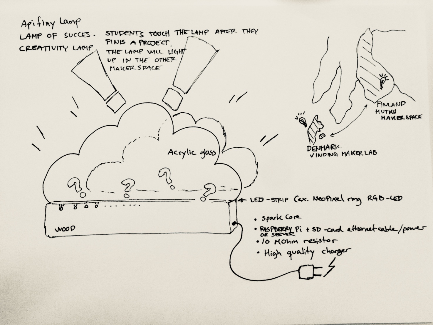
This lamp would be similar to the “friendship lamp” that lights up when touched by students from the other country. When a student has "the great idea" or an epiphany, he or she touches "The Epiphany lamp" in the lab and the lamp in the other lab will light up.
I intend the lamp to be cut like a cloud in light blue flourorised plexi glass, three clouds side by side, with LED-diodes and a bottom of wood (See the sketch below)

Spiral Development
The best way to explain the development process was - like Neil talks about - working in small spirals, so two steps forward one step back. I would come up with what seemed like a good solution and I would spend a lot of time making a prototype to get to the end and realize one good reason it wouldn’t work the way I wanted. That is why spiral development is such a good idea on projects like this. You often need to go through the entire process before you truly understand the issues. The faster you can go through the process the better. There is often no advantage of spending weeks cutting everything precisely out of metal when you could have learned the same thing hand cutting something out of cardboard fot a start. I benefited from the ability to do multiple iterations quickly and easily. Not only did the design improve with each iteration but so did my ability to make the prototypes. I learned from all my errors.The shape of the lamp
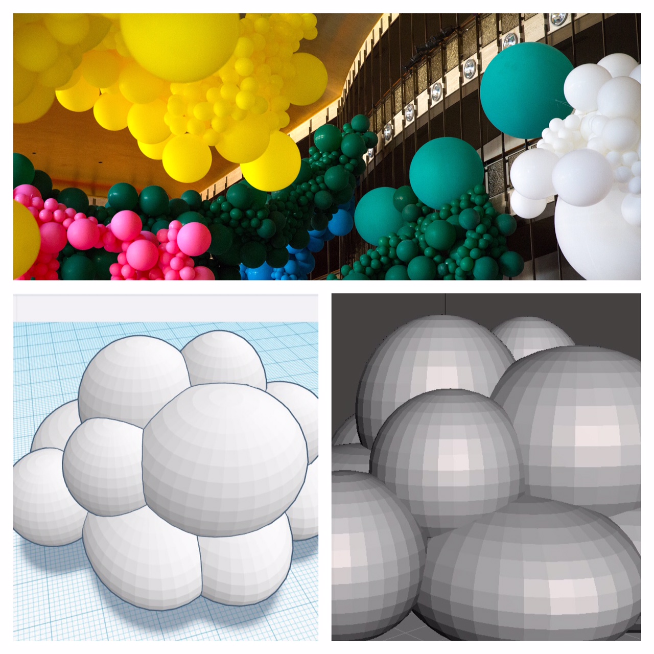
My first ideas for the design of the lamp was that it should be cut and engraved in acryllic with LED light shining through, but after the weeks of explorering 3D-modelling of diferent clouds in different materials as PLA, PTG and trying out Lorenzos FormLab 2 printer printing with transparent resin I am beginning to doubt my first design. I am thinking more in 3D shapes now than before. My conclusion for now is that I have to make bouth things work in my design. Some acryllic parts and some 3D-printet parts.

Inside the lamp
After completing the tasks in week 5 and 7 with drawing, milling and soldering the ISP and the Hello Echo board I am really beginning to think of the different micro controllers and wich one will fit best for my lamp. In the start my idea was to use an Arduino Nano for the job, but now I wonder if I could make a micro controller myself for the lamp. I just don't know about the Wi-Fi module jet.
Material list: (I'm beginning to think a possible material list through, so I don't end up missing some importent item for the lamp, having to bye it in the last sekond or maybe not being able to get it). For the fanal projct at the moment the material list includes flourorised acrylic sheets 4 mm thick in blue and white colors maybe try a frosted acrylic. Birch veneer for the base also 4 mm. One Spark Core for each light. One Raspberry Pi with ethernet cable and power or a Linux server for connecting the lamps. LED strips for the light. Conductive paint. A 4-wire-strip. 10 MOhm resistor. Good quality cell phone charger power supply, I have some old iPhone chargers I think I will use.


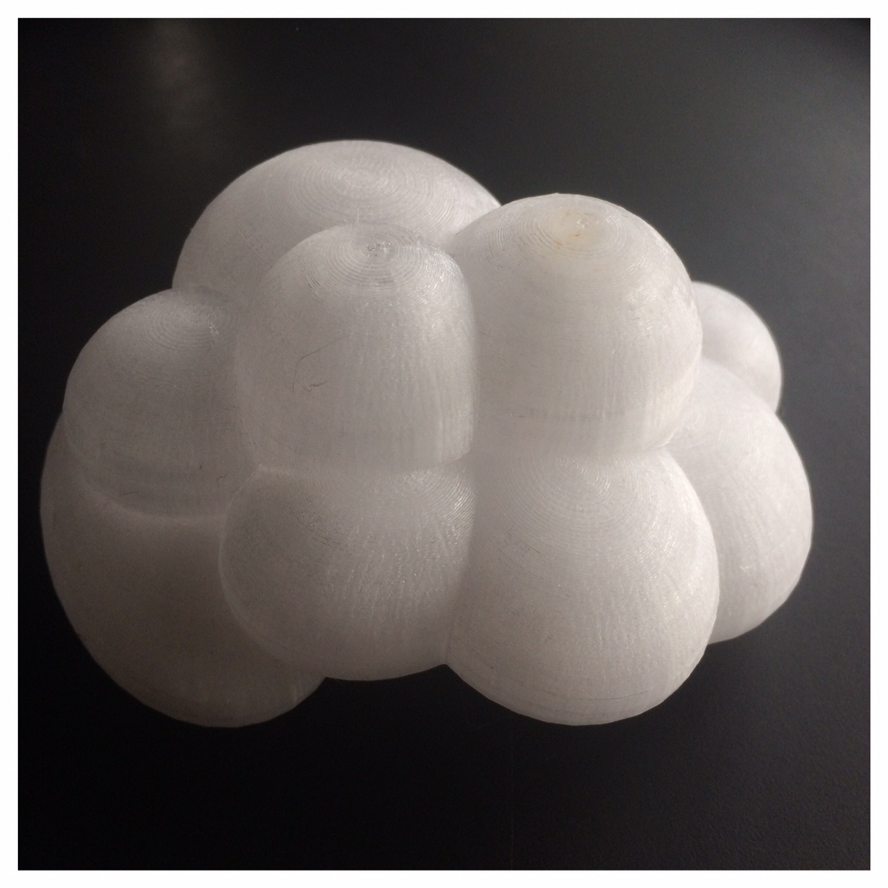
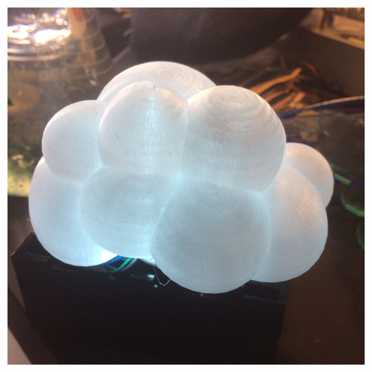
Today -in week 7- I just finished a 3D-print of my cloud printed in PETG on a Prusa i3. It was a 19 hour print with some different kinds of support. I printed it in transparent PETG so I can sample different kind of LED-ligt sources. On picture number 2 I just put in a simple LED ring in to get a idea of how tranperent it is.
Testing eletronics for the lamp
I am starting to test the different electronic parts I need for the lamp and also sampling different code parts for the arduino to get a overview for what I need in the end. I want to build the inpart of the lamp with an Arduino UNO and the breadboard for a start, and then hopefully later on create my own microcontroller.
Underneath on the pictures I'm sampeling some RGB-led's ws2812b where you in your arduiono code can control different colors, timer and how many led's you have in the circuit. I am using the Arduino UNO and breadboard to learn the different possibilities and code parts I need. I also want to sample this wi-fi module to connect the different lamps with a server and make them interact.
Sampling with a NodeMCU ESP-12e
So these last couple of days I been wondering what to take with me from the last weeks in order to completing my final project. I know for sure that I need to understand my board and my final project better, so I have tried to make the lamp with an NodeMCU esp12-e and two ws2812b 'adreeseble LED's to get a better insight of my final project.
On the images above I'm in the lab working with an ESP-12e module and a breadboard and suddenly find out that I need two pieces af 100K resistors. In the Lab we only had the little SMD components (for soldering on PCB's) in the inventory, therefore I soldered small pin-cables on so I could use it in my breadboard. It worked perfectly so I could proceed with testing parts for my lamp.
For testing I found out that you can get a little server space for free on io.adafruit.com. Adafruit free server space It's not a lot but a great help when you are testing IoT products where you sometimes need a little server space
I added the board node MCU 1,0 (ESP-12e module) to my ArduinoIDE together with the Adafruit Libery (lib) and ran a code sample for Arduiono. I changed the server info and added the AIO key a got from Adafruit in the script and it worked. As you can see on the pictures below I am now sampeling the lamp-1-master. There is one more lamp added the server lamp-2-master (that is going to be build by the kids in Mutku Maker Space in Finland). As for now the lamp is responding to the server as you can see by the number 1 and as you connect with the lamp the brightness will turn up and hopefully with time connect to the other lamp.
Tinkering with the teachers at a local primary school
After good amount of meetings and tinkering together with teachers at a local primary school and some facetime meeting with Heikki in Finland I realized that I will get the best result for this first product with a board where the teachers also could do some experiments. Here I was quite inspired by Neil Gershenfeld's talk about Seymour Papert's Seymour Papert attempt with the interactive turtles and the importence to make the kids make the interactive turtles. I think it's important to get the teacher to make their own version of the lamp, with their own design and connect it to my main lamp for creating the network. My thoughts are here that the teachers then later on can experiment with the kids. In this way, I think I would have the opportunity to pass a learning experiment rather than just giving them a finished product. So my dream is that this could be a course in the primary Schools' Maker Spaces that I work with, where students produce and experiment with the lamps that are connected to other lamps in other school labs.After my meetings with the primary schools teachers I decided to try to make a version of a FabKit 0.4 board and a version of the Satshakit board and burn bootloader as an Arduino so the teachers have the opportunity to use Arduino IDE for programming. My reason for doning this is a hope for getting teachers to code/program more in the schools Maker Spaces than what I see today. The few teachers who do a little coding and programming in the primary schools in Denmark are familiar with Arduiono IDE and in this way I hope that this project can make them work more with mico controllers and IoT projects with the children. So a kind of kickstarter project for them to engage in.
I started out with reading the datasheet for the ATmega microchip (8 bit, 32 KB) that was the microchip used in bouth boards (the FabKit 0.4 and the Satshakit) trying to figure out where each pin went and what it could be used for. I found this little great picure at the ATmega that was really helpfull.
When I came to perform the various steps in relation to "burn bootloader" and try to upload code, FabKit started to smell a bit and "magic smoke" occurred, oh no! Then there was nothing to do, it was burned. I realized that I must have done something wrong with the connection of the GND and my FabKit. I therefore chose to make another Fabduiono model (I thought I might as well try to make another model, when I had to make a new one anyway... long live variation).
I decided to make an AKF Anna Kaziunas France Fabduino; because it looked quite small and I really liked the documentation/tutorial site of Anna Kaziunas France (check this link): Tutorial site of the AKF Fabduino
This went a lot better. I milled, soldered, burned bootloader and programmed the Fabduino with some basic code examples form Arduino IDE in one day. I will use this AKF Fabduino to become wiser on the code sections related to my lamp projct and to find out what I need (or may be without) in relation to my Final Project.
Hart & Brain
After working with the AKF Fabduino and the FabKit that I made I wanted to try putting my own little touch on a Fabduino-version. So for the hart and brain in my lamp I created this little Fabduino with my handdrawn cloud as the frame. I also attached a female socket for the FTDI so I later kan plug in my ESP-module. I made sure that every pin was available so I - and others - have the opportunity to continue experimenting with the lamp. I think in time the students should be encouraged to hack the lamp, giving it some of their own soul.
Coding and programming my board
So I burnt bootloader on my version of a little Fabduino. For this job I used Arduino IDE with the folllowing settings under tools:
board:"Arduino Pro or Pro Mini"
processor:"ATmega328P (3,3V, 8 MHz)
portThe port that appears when you plug in your board, in my case port3
programmer:USBtinyISP
And then "Burn bootloader
When this was done I neede to read the datasheet for the ATmega328P chip and find out with pins I had available. So my traces, the datasheet and with ins can I use. I modified some basic code examples in the Arduino IDE under: files, examples, then 01.Basics and 02.Digital and it worked on the board. I just had to change the pinnumbers.
The cloud button
At the moment I like some kind of touch button on my lamp and I'm also working with a code part and microcontroller set up where there's just such a touch button. I have therefore made a small copper cloud with the same file I used to laser cut and engrave the acrylic cloud for one of the lamps. For the cobber cloud I used Fabmodules and the Roland mill. I engraved the curves of the sky just as we make traces on the PCB and the sky's perimeter like when we make an outline or cut out. I think it came out butiful and when it's glued to the concrete base I think it's gonna be great.
The light
Right now I am working with adreesble RGB LED's called ws2812b and also the ws2812 (intelligent control LED) WS2812B-LED-datasheet. I rewrote my code so I can sample with up to 20 LED's, but in the end I think the final lamp will have the amount of 8 LED's, but right now I need the possibility to add more if it's nessesery for the design.
The ESP
Where should I starte here. Hmm the ESP is right now a little like the story about Ahab's quest for the White Hvale. Right now I am really struggeling with getting this to work. I made a quite big range of different ESP-boards and modules and for everyday I think I get a step closer. I managed to flash my code on one of the ESP12e-modules after a lot of trial and error and it connetcs to my iPhones shared internet or hotspot.
As you can see on the picture below the ESP is connecting to my iPhones shared internet. In the code I managed to flash to the ESP12e it says that it should connect to the Internet called "iPhone" with the password "skylampe". In the upperpart of the picture of the iPhone is says in danish: "Internet sharring 1 connection". So it definitely connects to my phone.
A little breakthrough
Then a little breakthrough came. I had made a little board with an esp12e on similar to Sander Van Vliet who had made a redrawing of Neil's hello.ESP8266-12E.ftdi board hello.ESP8266-12E.ftdi. I corrected a few small errors that Sander himself describes in his student site under final project. With this board I had a succes with flashing my code to the esp12e.
Then I downloaded this software called PuTTY, where I could monitor signals coming into my computer and which port it's using. I could see when I touched pin 2 (the ADC, TOUT) on my esp I got a "TOUCH" signal comming into my computer and "FIRST IF, LAMP 1=1, LAMP_1_master, TOUCH, TOUCH..." So it was actually performing my code.
Now the board connects with the esp to the server using the key from Adafruit I wrote into the code.
My next step was to draw a new schematic and figuring out the puzzle of the board in Eagle including the modifications and the extra components I soldered to the other ESP board. I made the schematic and added one 100 K resistor and three addistional traces.