Assignment
Group assignment:Characterize the specifications of your PCB production process
Individual assignment:
Make an in-circuit programmer by milling the PCB, then optionally trying other processes
Fab Modules
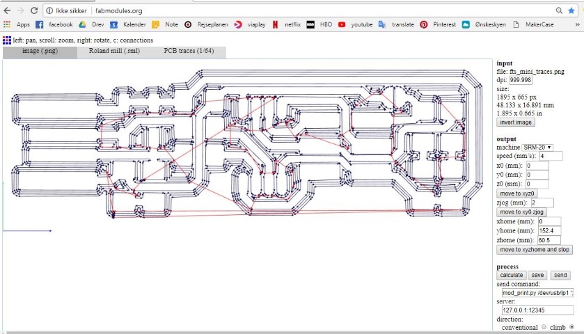
Fist I insert the PNG in Fab modules.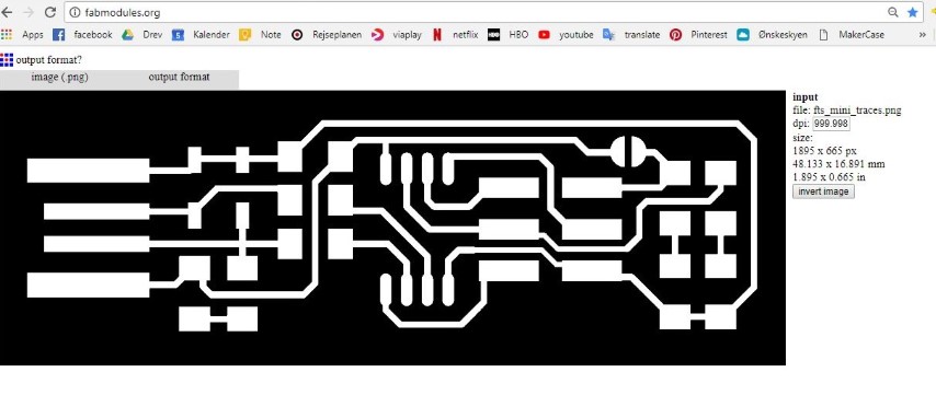
Then I choose the Roland mill (.rml) because this is the machine we have in the lab.
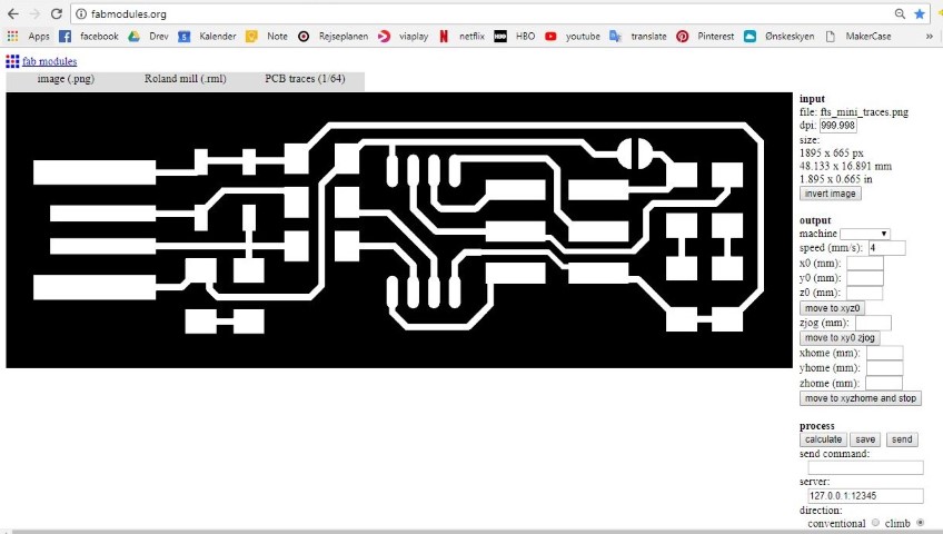
Then I choose the kind of traces I am using. For the inner I am using the PCB traces (1/64). And for the outline I am using PCB outline (1/32).
In the pictures I am using the inner traces (1/64).
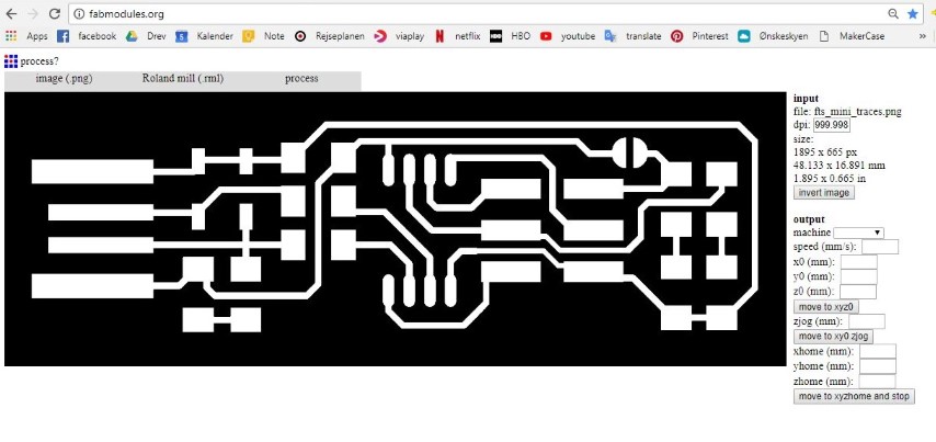
Then I look in the bar on the right and on the machine I choose the machine I am using. I am using the SRM-20. Then it will automatically choose some settings.
By default the x0 y0 and z0 is set to 10 mm. This means that it will start the job 10 mm above, and this we don't want. So I set all of them to 0.
After you've choosen this you press the calculate button.
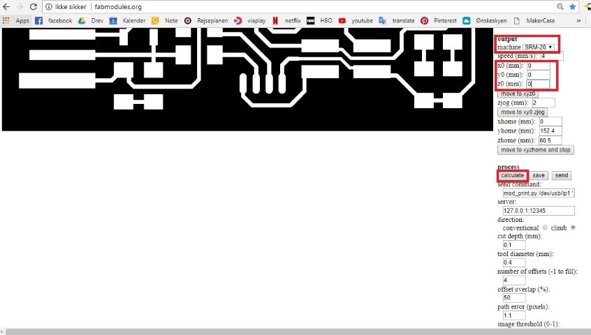
Then it will calculate the toolpaths. This can take time with some designs.
And if the toolpath looks good and nothing is connected that should not be connected. Then you save it and the file will be downloaded. If there is a problem you have to fix it in the eagle file or "cheat" by changing the tool diameter down. But have in mind by changing the tool diamteter down it will remove a bit more everywhere compared to if you would just change it in the design file.
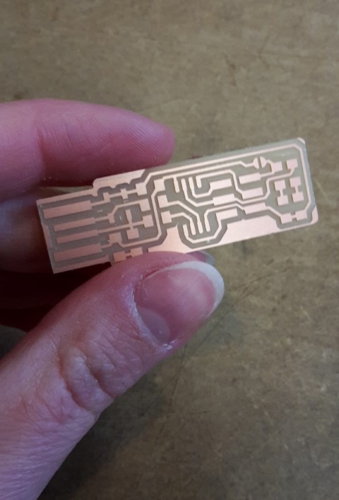
Milling machine
I used Brians version. It was very easy to make and everything worked as it should.I downloaded the pictures and used fabmodules.org to converte it to a milling path the milling machine can read. It is important that you remember to set the inside and the outline correct.
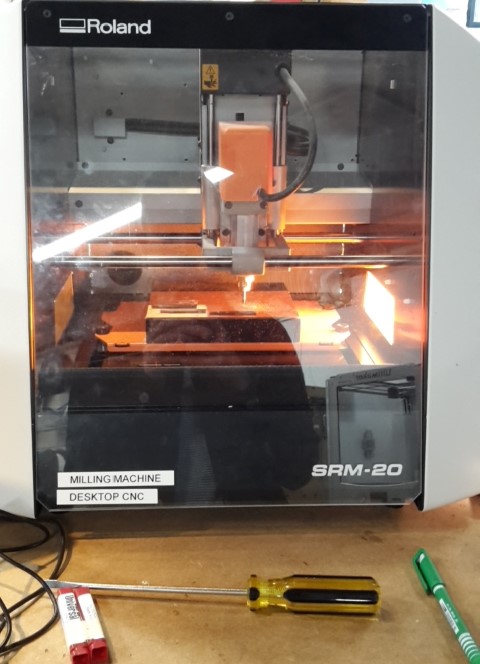
When you use the milling machine, you take the correct drill and mill the inside of the board first. The way you set the machine is this way:
- Make a dot/x on the board with a marker.
- Use the arrows on the computer to control the machines way of moving from left and right.
- Notice that there are different speeds to move the machine with.
- When you think you are on top of the x you made go down towards the plate.
- You shouldn’t use the arrows to go all the way down to the plate.
- When you are close enough, loosen the drill and set it manually to the top of the plate.
- Tighten the drill again.
- Remember to set the y,x and z to the right on the computer. In this way the computer will remember where you started.
- You can also take a picture or write down the coordinates. In this way if something happens to the computer. You can manually set the coordinates.
- Take the drill up using the z arrows.
- Click “cut” now you come into a window. If there are any files, click delete all. Then choose the inside of the circuit board file.
- Drill.
- Change the drill. Be careful not to drop it because it is very delicate and breaks easily.
- You can for example put the protecting material on before you loosen it.
- Remember that the drill should be a bit away from the plate.
- Click the x/y to origin.
- Click the arrows to get the z closer to the plate.
- Loosen the drill and manually set it on top of the plate. It should be in the x drew in the beginning.
- Set the z on the right.
- Take the drill up in the air again.
- Click “cut” now you come into a window. If there are any files, click delete all. Then choose the outside of the circuit board file.
- Start the machine.
- Now it should drill the outline.
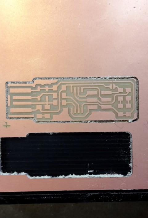
- Take the whole thing out and use some tools to wiggle the circuit board out.
- Tadaaah!
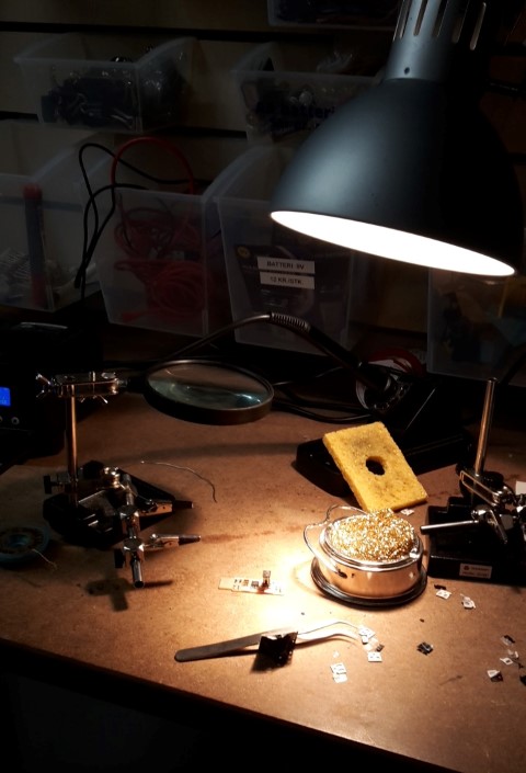
On Brians page there is a recipe list of all the components you need. An easy way of keeping track on what is what is that you can write the names on a piece of paper and place the small components next to it. You can also make a small box with holes for each component.
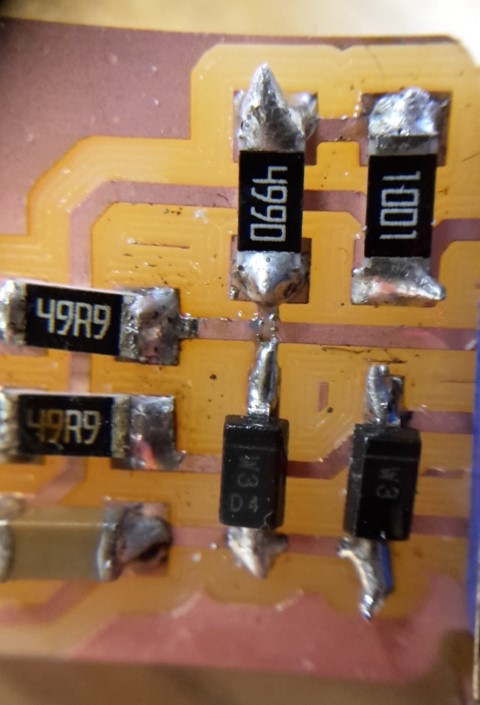
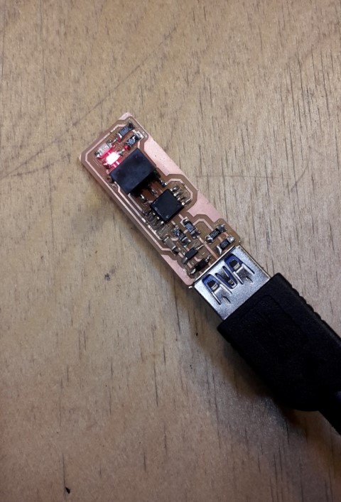
After you find all the parts you can just follow the pictures on Brians page. it is really easy to understand. I only needed some instructions in how some of the parts have a stripe of black or something, so on the drawing you can also see a black stripe, this is the way the component should be turned.
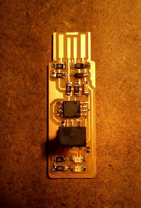
I haven’t been soldering before, so it is not the most beautiful solderings but hopefully this will be better.
I programmed it on a computer with linux because it said that this was the easiest way. I had no problems with this. I also used the blue box for it (AVR ISP MK II).
So now it should be able to program other small circuit boards.
Problems...
I’ve been having some problems with my programmer. It worked when I programmed it and there was light in it and everything. But now it doesn’t work. My computer with Windows 64 recognize it when I plug it in now, but it can’t talk to it.I’ve tried re-soldering some of my “not so pretty” solderings.
I’ve checked the solderings with a multimeter and there is a connection where there should be a connection.
The things i changed:
I desoldered the jump button.
I’ve been adding soldering to the end that goes in the computer.
I programmed the programmer with a Linux computer. So when I wanted to use my own Windows computer for programming the button, I had some trouble. We figured out that I was missing some programmes, so I needed to download the Zadig2.3 version.
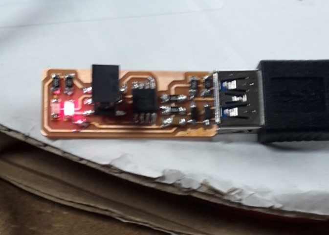
I’ve now made a new programmer also using Brians version and programmed it on a Linux computer. I think I might have put a wrong capacitor on the first I made, so this one should be perfect.
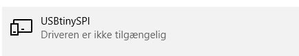
My computer can still not talk with the programmer, but it can see that it is plugged in. In the picture below you can see that my computer can see the USBtinySPI but the text says "the driver is not available".
I’m trying to download this to see if it helps:https://learn.adafruit.com/usbtinyisp/download
It did not work.
But this did!:
https://rayshobby.net/dead-simple-driver-installation-for-usbasp-and-usbtiny-on-windows/
https://learn.adafruit.com/usbtinyisp/drivers
After I installed this on my Windows 64 computer everything worked!
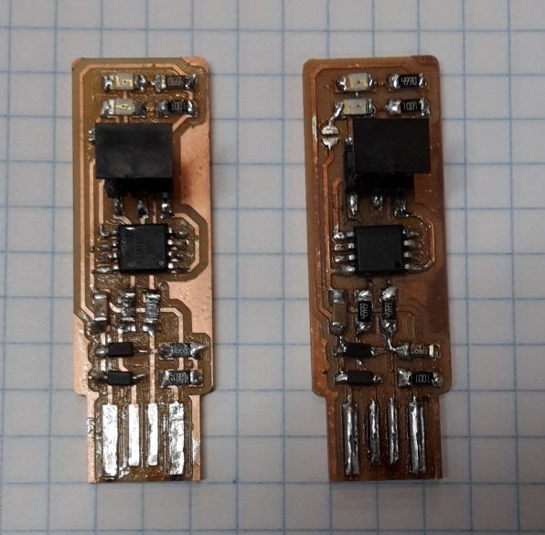
Here is a picture of the old programmer (on the left) and the new programmer (on the right).