Assignment
Group assignment:- Actuate and automate your machine.
- Document the group project and your individual contribution.
Group page
See more on the group page HERE.Assembling
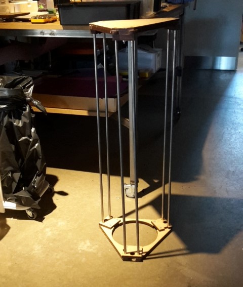
I have been part of assembling the machine when we got the parts for it.At First we assembled the machine with normal steel rods. We quickly discovered that the steel rods might not have been completely straight. We also tried the bearings on and concluded that it could not run good enough on the steel rods. We then ordered the precision steel rods.
I helped with glueing the pieces of MDF together. We glued them together on the "bad" steel rods but we were able to get them of when we got the precision steel bars.
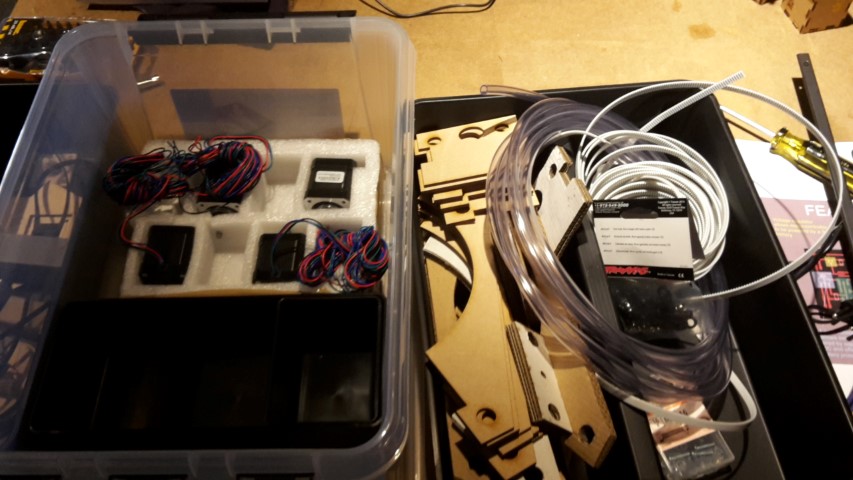
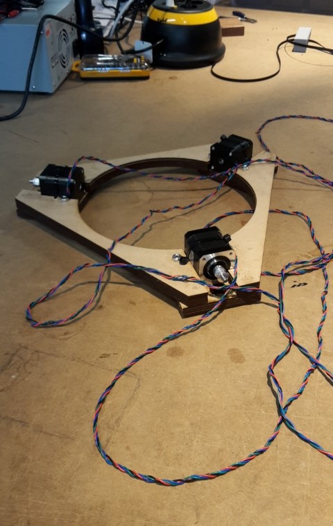
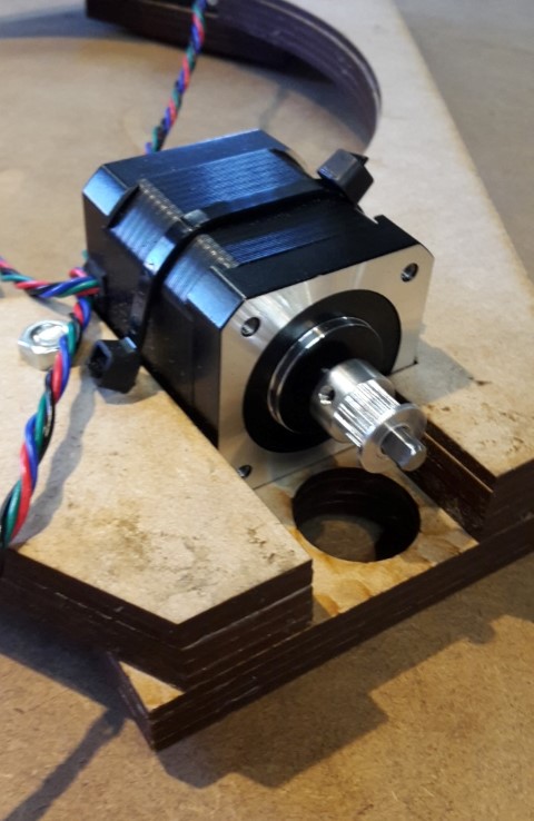
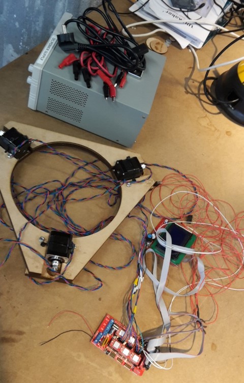
We have four Nema17 motors that we are using on the top of the machine to control the belts on which the middle part is running on.
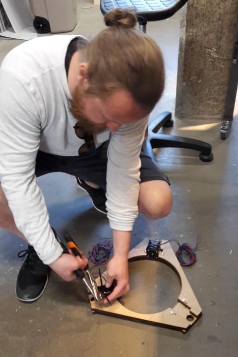
We drilled holes in the top to attatch the motors with strips.
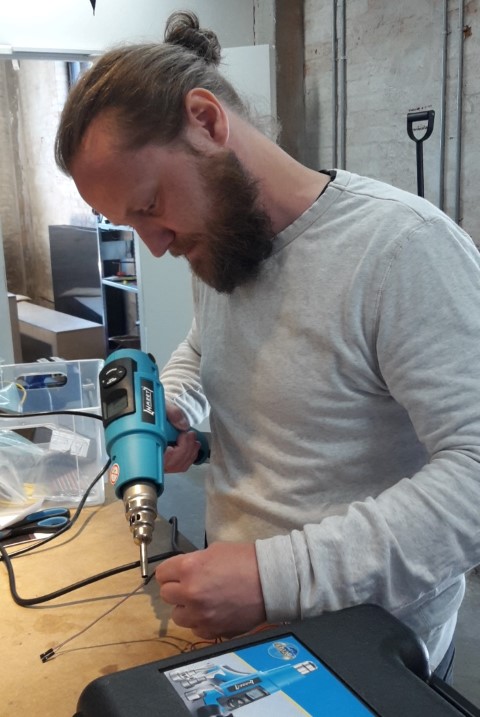
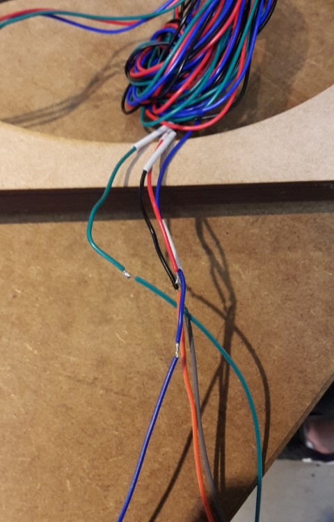
I soldered some of the cables together with Peter. We have added shrinkable tubing to the cables we are putting together so the wires whon't be exposed. Peter heated the shrinkable tubing
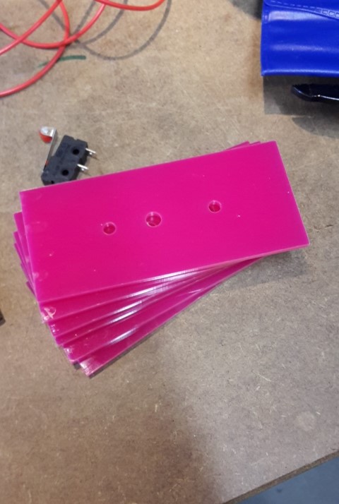
The pink plates for the side is cut on the laser.
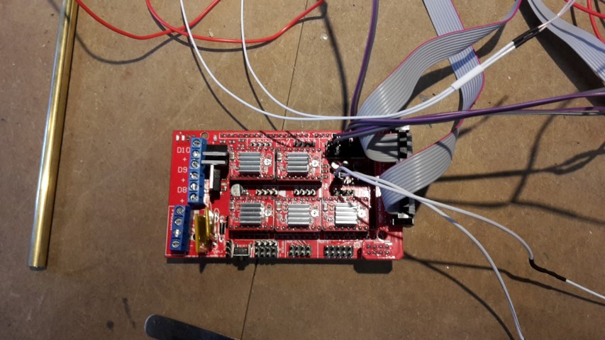
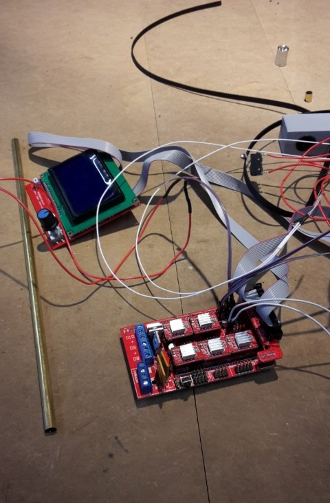
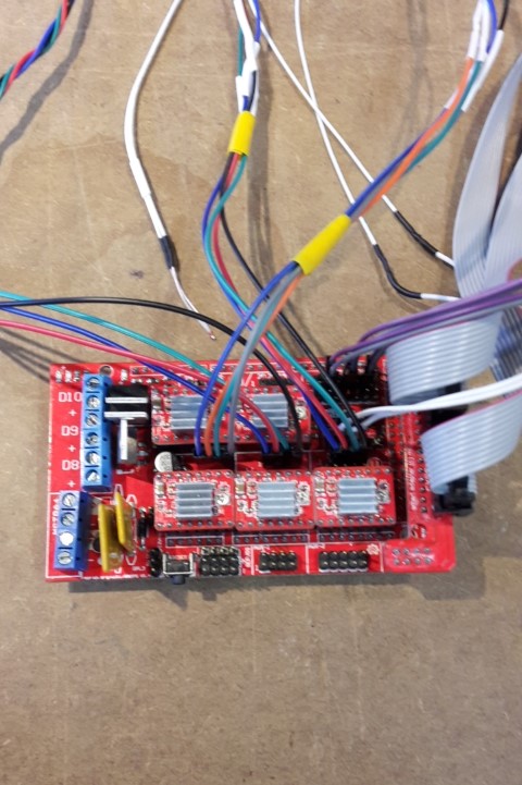
We connect the screen, the temperature overwriter and the end stops to the Ramps.
I helped twisting the wires so they won't be tangled up in each other.
The motors wires are attached to the Ramps.
I soldered some of the endstops to the wires.
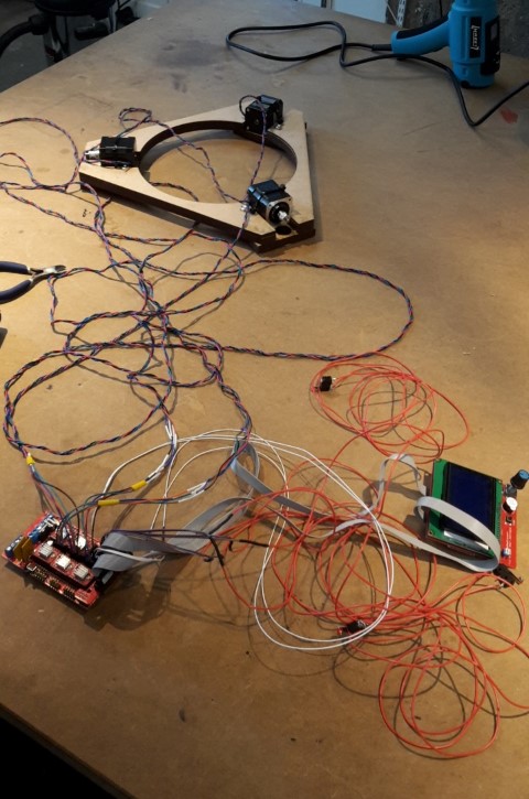
Temporarely we use the power box for the power.
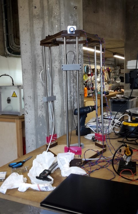
The top plate with the moters is attached to the precision steel rods. Afterwards we had some problems with getting the belt in the bearing holders. But with several tries from almost everybody - we succeded.
I cut the brass tubes so they would be the correct length for the machine. If the bars are too long, the machine whon't be able to print as high.
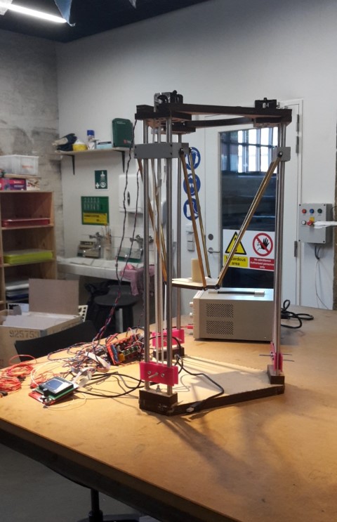
The middle piece for holding the extruder is fastened to the traxxas rods and the brass tube.
It took teamwork when we had to glue the traxxas inside the brass tube because they needed to be aligned.
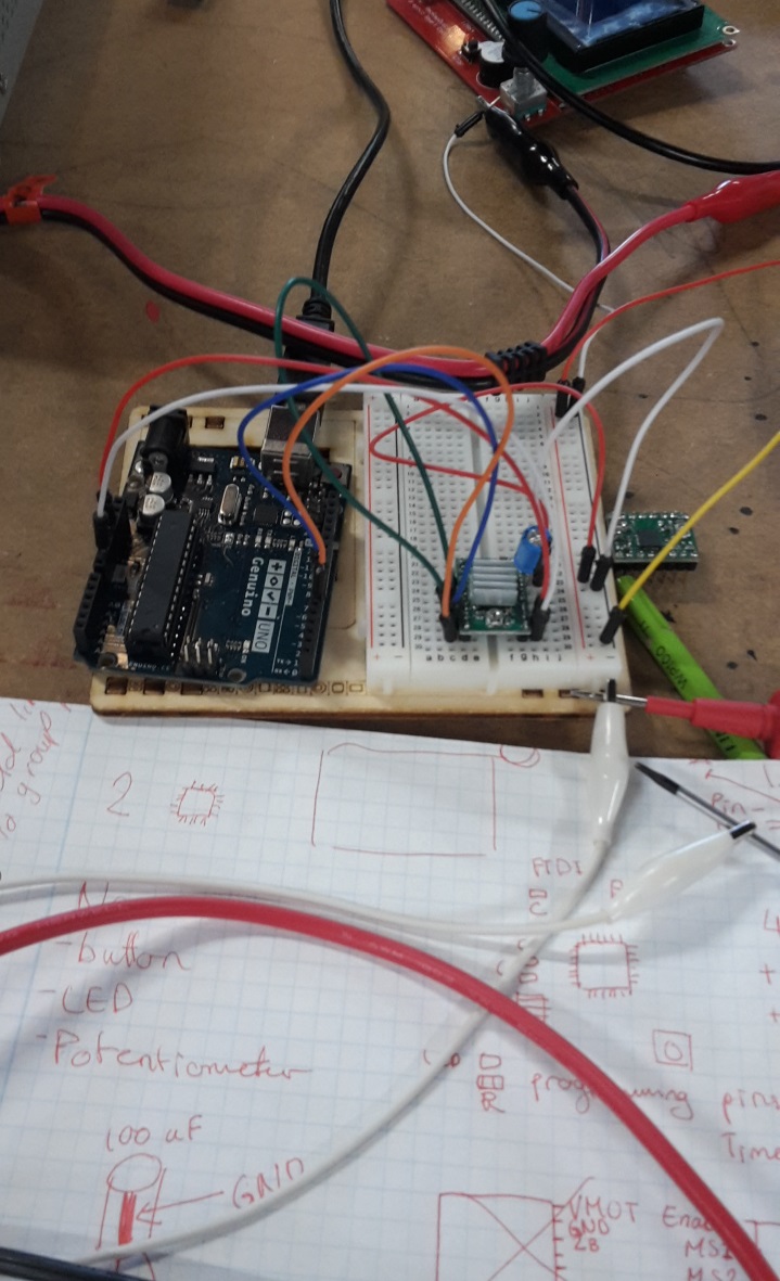
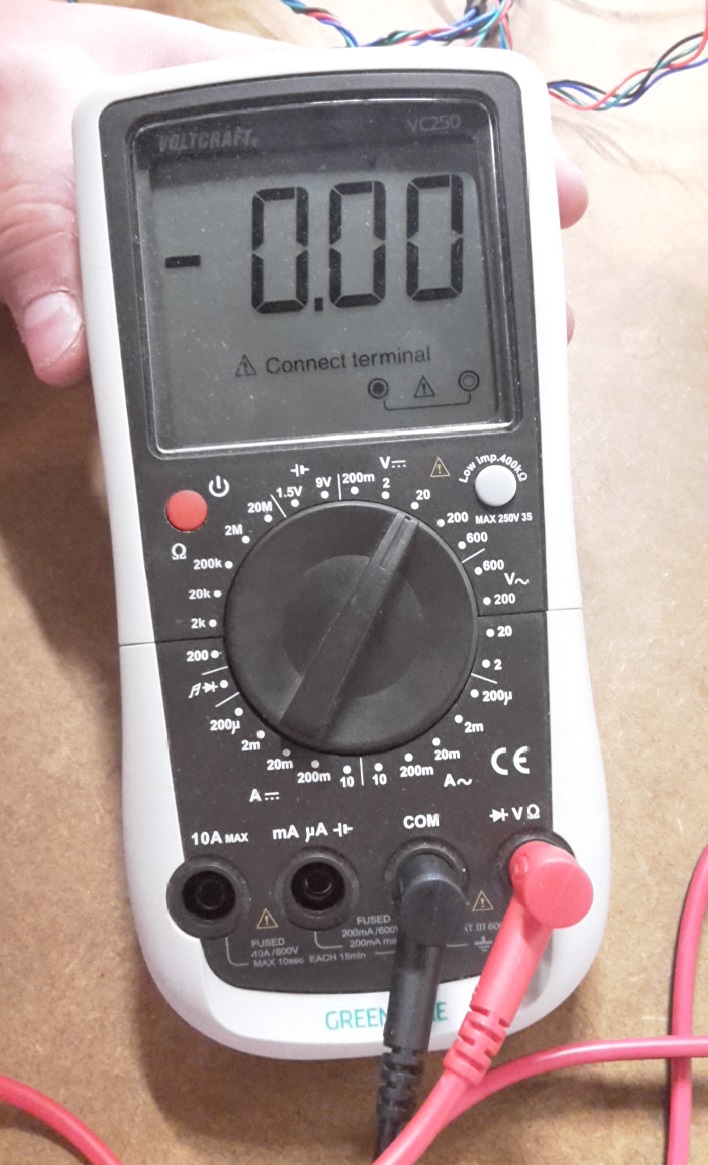
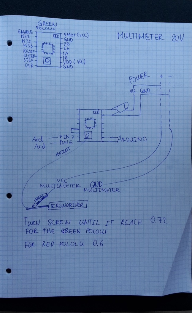
I adjusted the Pololus by using a multimeter, a breadboard, Arduino, 100 uF capacitor, wires and a power supply.
The power supply should be set on 12V and 1.8A for the green pololu.
The multimeter should be set on 20V. GND should be connected directly to the board. But the VCC should be attatched to a screwdriver (check if curent is going through the screwdriver before you use it), then when you are turning the screw it is showing a number on the multimeter. You should keep turning clockwise until you hit 0.72 on the multimeter for the green pololu.
Final result
A manual test and a mechanical test is shown HERE on our group page.My tasks
- Twist the wire for the Nema17- Cut the middle arms
- Soldered wires
- Glued the brass tubes and traxxas
- Screw on the End stops
- Configurating Pololus
- Adjusting the side bars by filing, sawing and drilling away material
- Helped assemble and glue the MDF pieces together
- Buy stuff in hardware store (Bauhaus)
What could have been better
We had some troubles with chinese pololus where some of them burned. Unfortunately we had to wait for some real pololus to come home, this slowed the process.It is also not optional that we made the frame of several 3mm MDF and glued them together. Because it is very easy to unalign the many pieces of MDF and this will make the whole structure a bit unstable.
It also makes it a bit hard for the bearings to run.
Unfortunately we had an accident with our CNC machine, so it was not working at the time. But it would have been optimal to make it on the CNC.
There were a lot of the components that we waited for, so next year I think our lab will have more motors and stuff in store so we don't have to wait.