V shapes
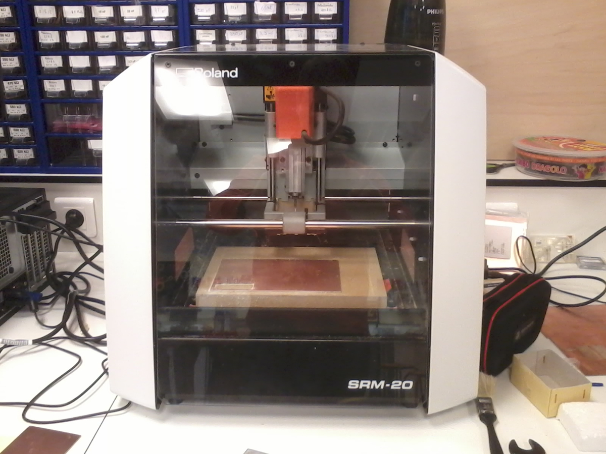
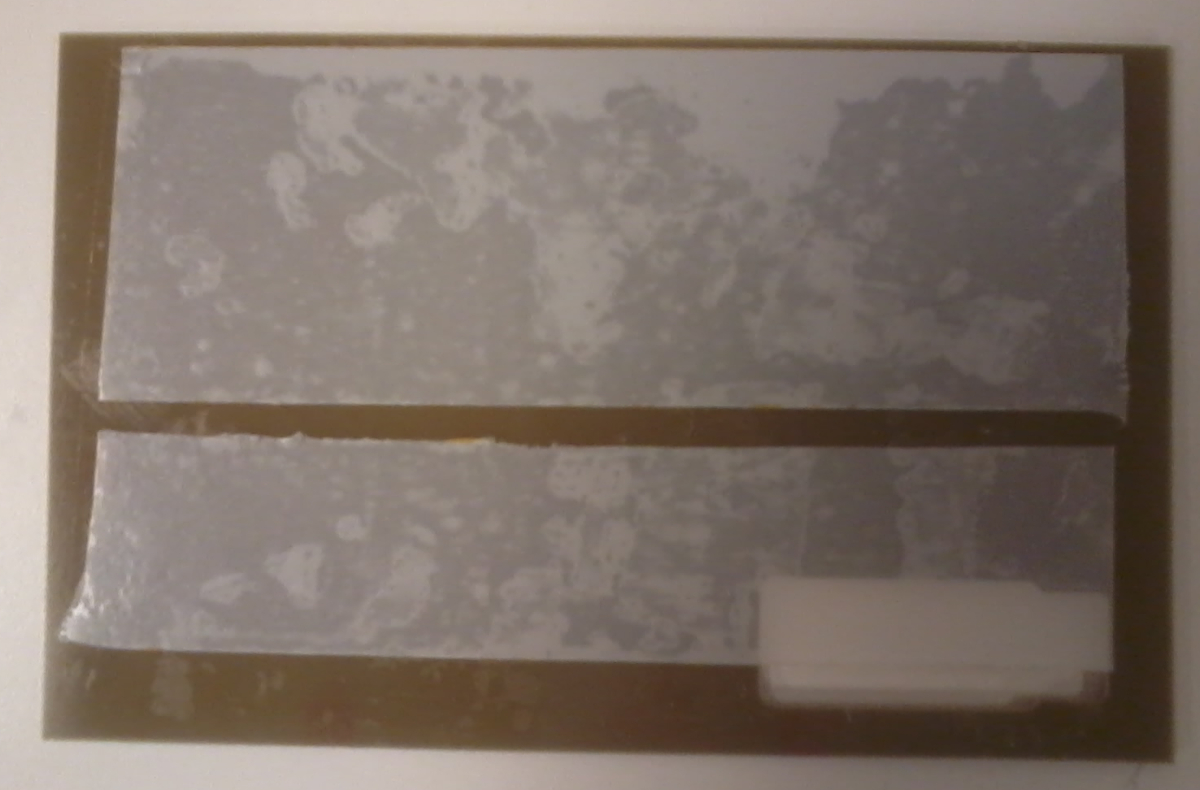
There is two way to make a PCB, engrave or mill it and use chemical process. This week, we had to mill a PCB isolating tracks with a mill tool.
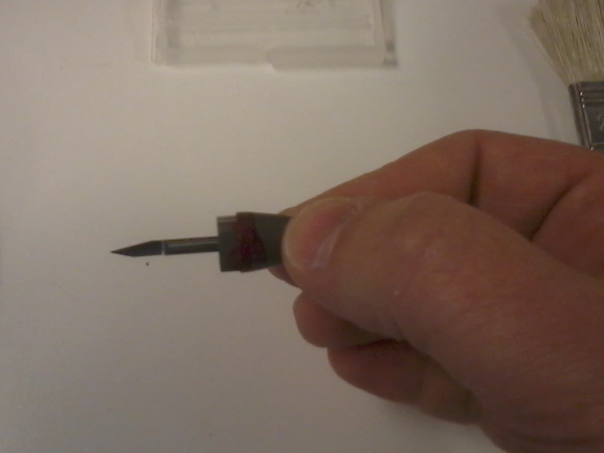
To mill PCB, you can use a cylindrical tool with a very small diameter or a V shape wich is half a cone.
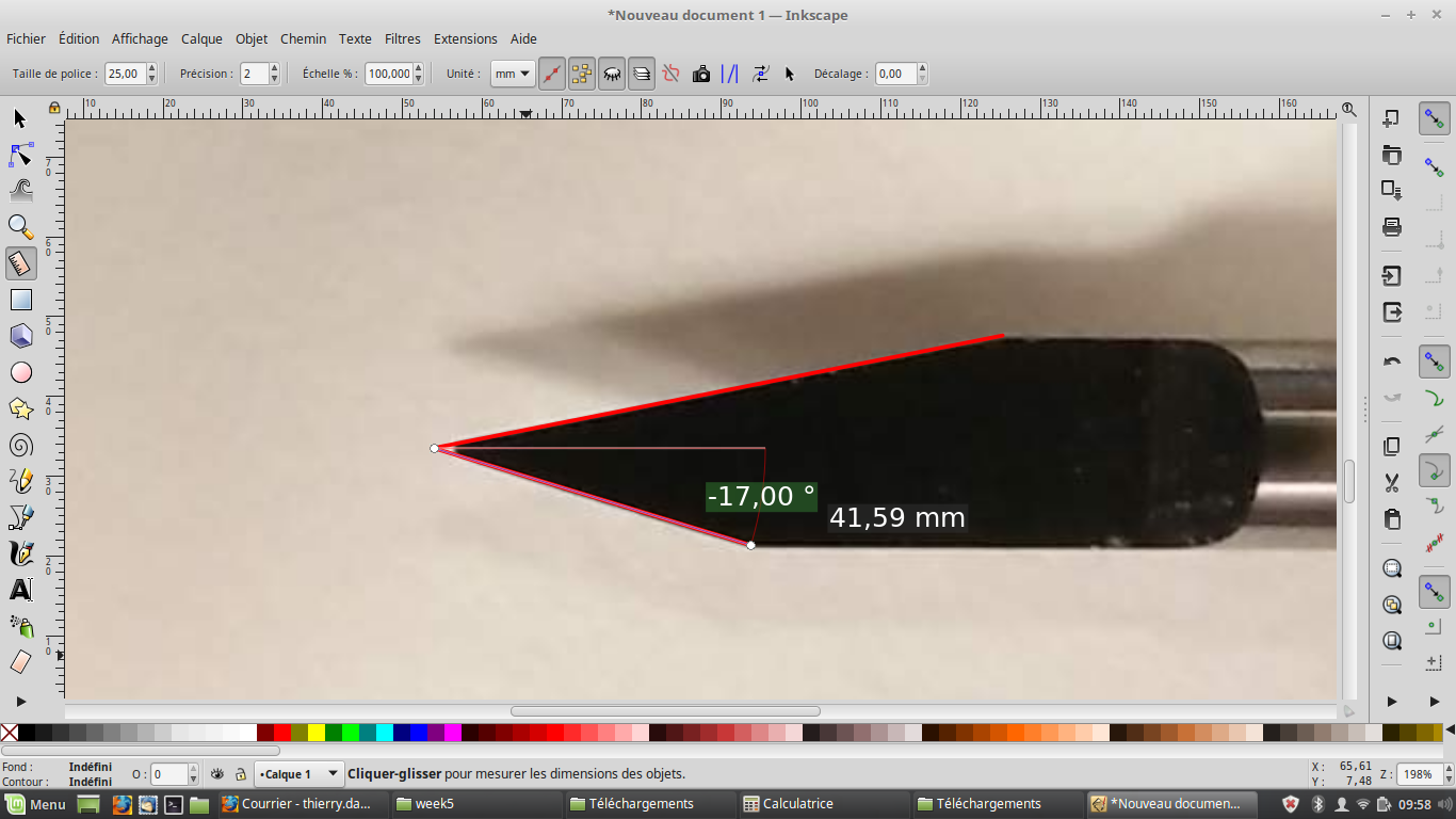
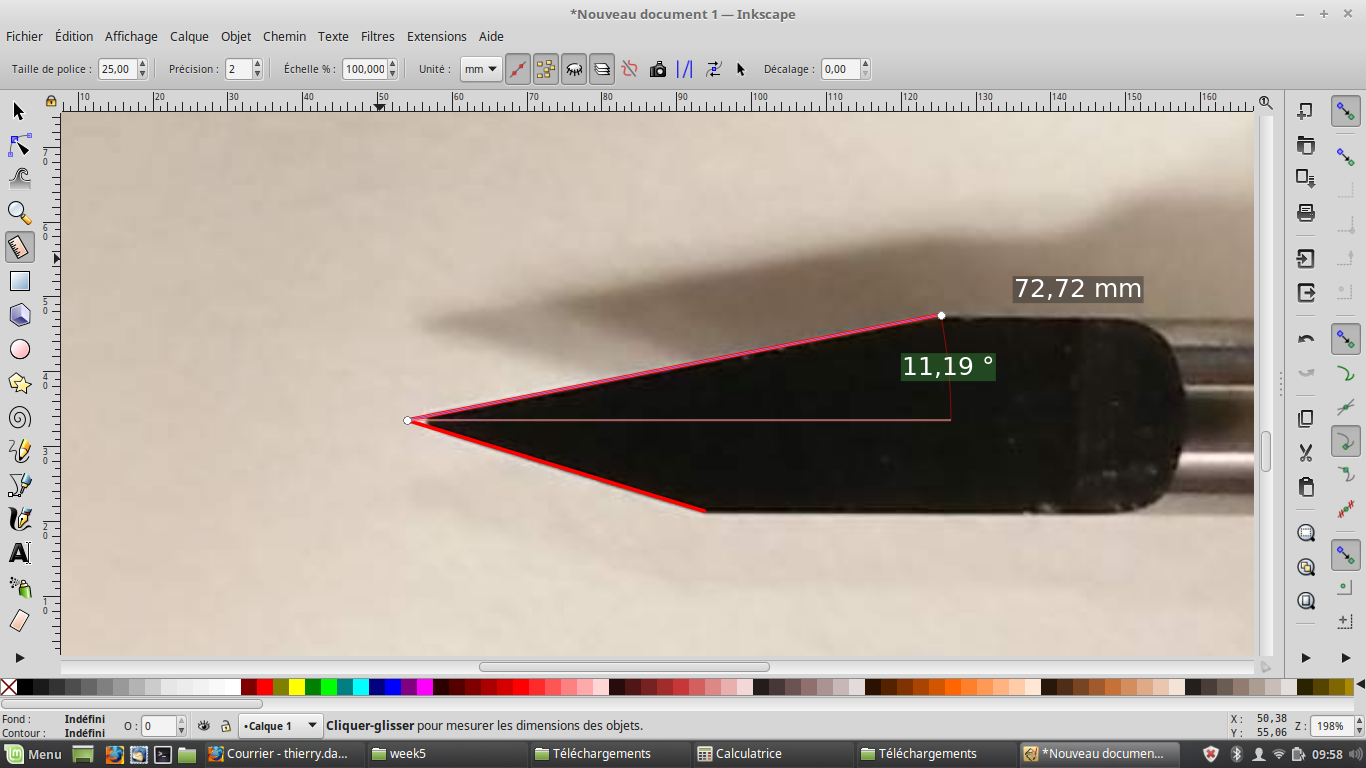
We found V shapes in the Lab but without any reference on it. It seems to be a 30° Vshape but we were not sure. So, I first wanted to verify V shape angle.
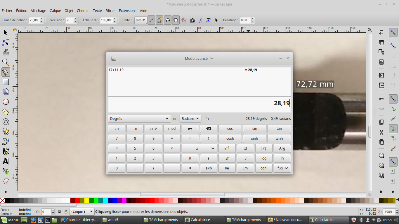
With inkscape angle ruler, I found 28°. As it can change if shape face is not perfectly horizontal, this V shape should be a 30°.
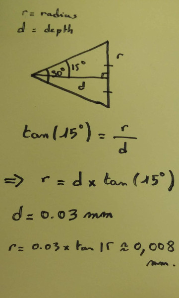
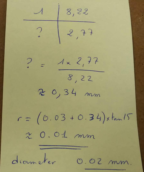
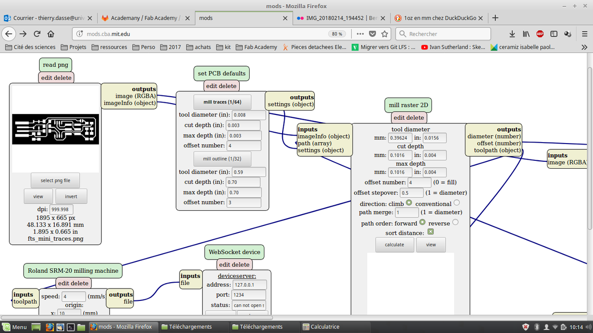
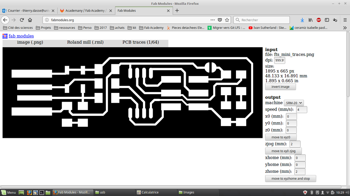
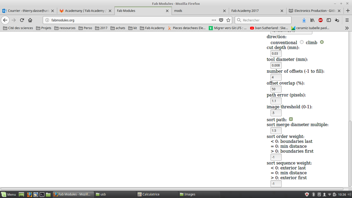
I calculated "diameter" for a 0.03mm cut depth and found a radius of 0.008mm and used this value in fabmodules to cut my board.
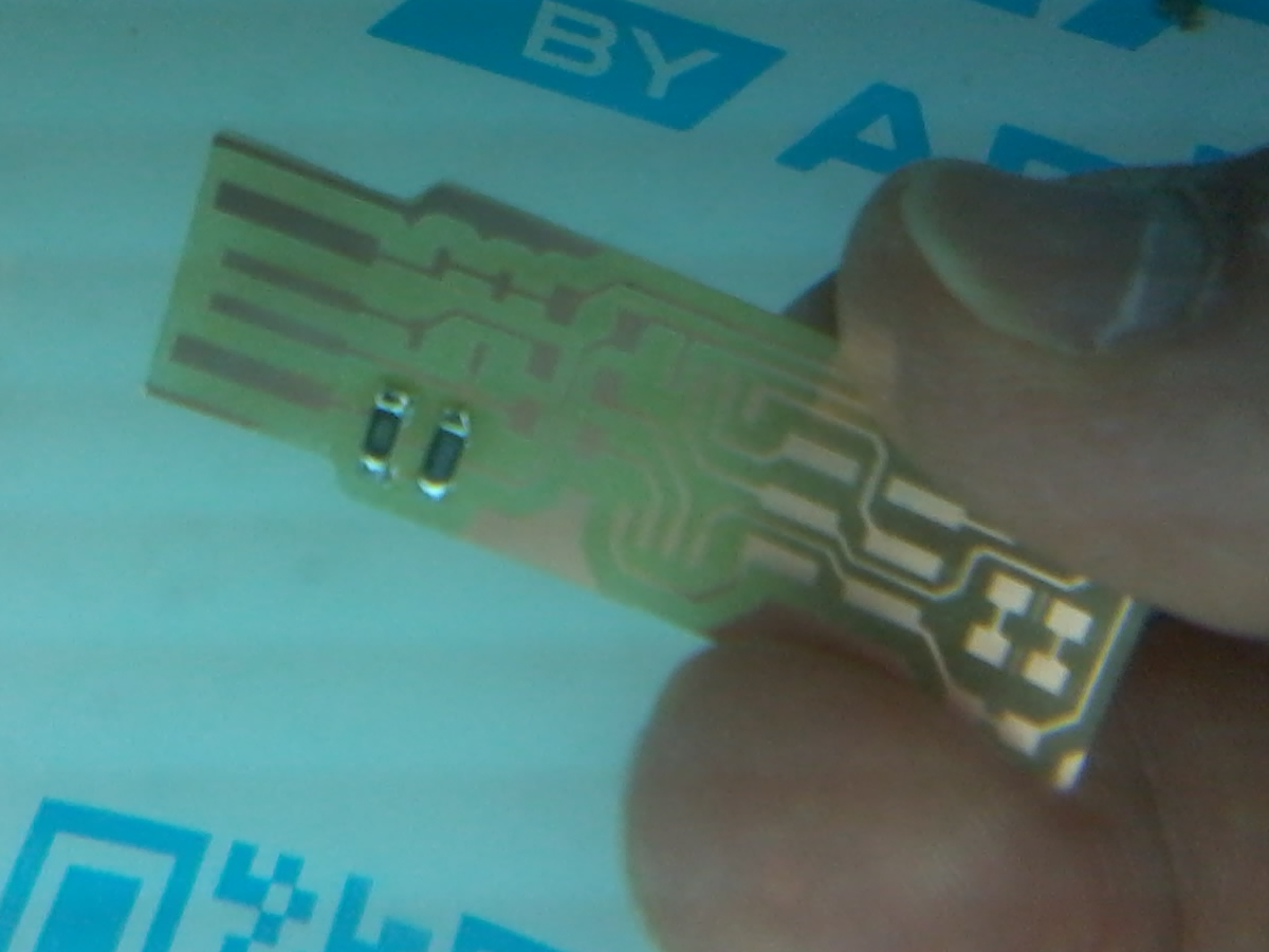
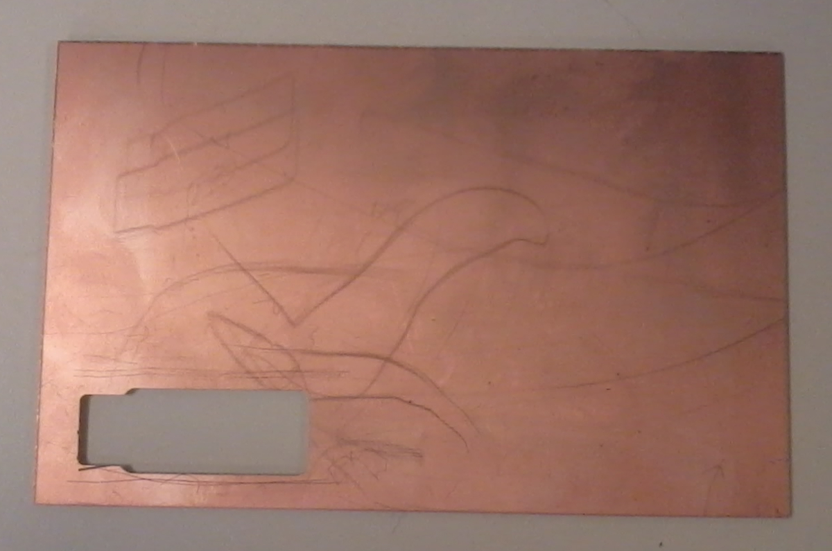
My board wasn't well cut. Reasons are I made a first mistake between radius and diameter and my diameter should have been 0.016. Second is
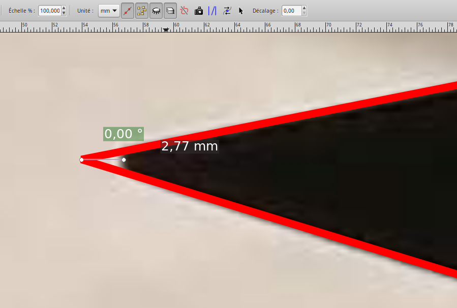
that V shape is not sharp but round at the end. So, when you make your origin, your are not at triangle vertices. And third, there should be
some vibrations
Because, my board didn't work (see Generate traces and outline files), I decided to measure V sphapes "diameter" directly.
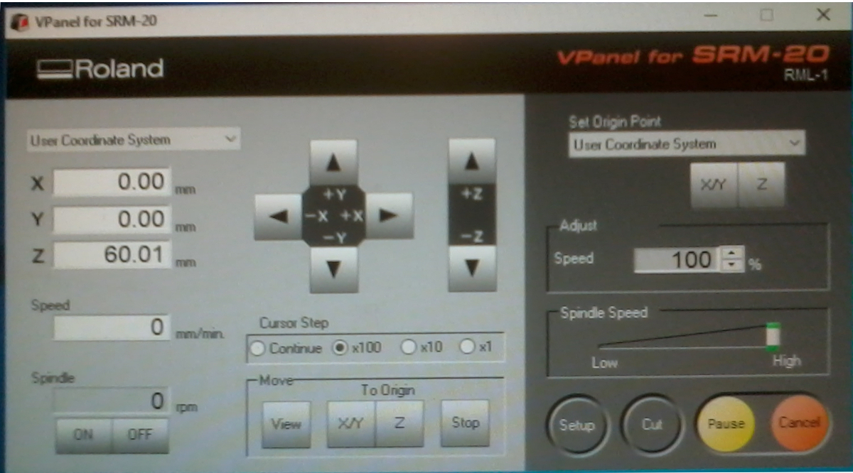
I wrote a file test wich mill only one line, one cm long (I read fabmodules generated files to understand how they are made before) :
PA;PA;VS4;!VZ4;!PZ0,200;!MC1;
PU100,100;
Z100,100,-4;
Z100,1100,-4;
PU100,1100;
PA;PA;!PZ0,200;PU0,0;!MC0;
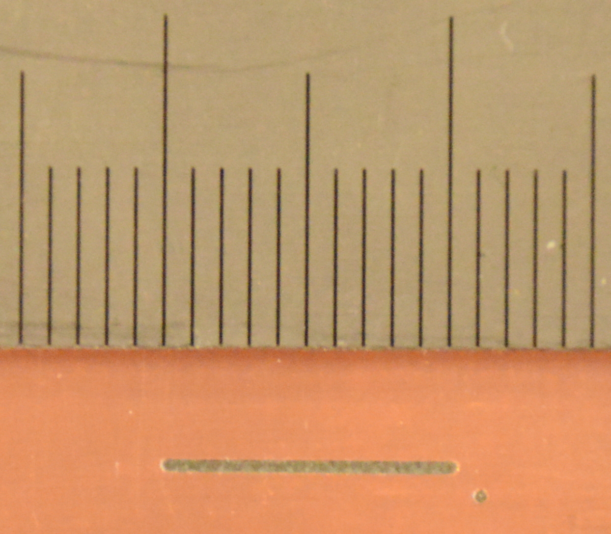
Then, I took a picture of the result with a ruler. On Gimp , I measured than 1mm is 56px and linewidth is 27px. So, linewidth is 0.46mm.


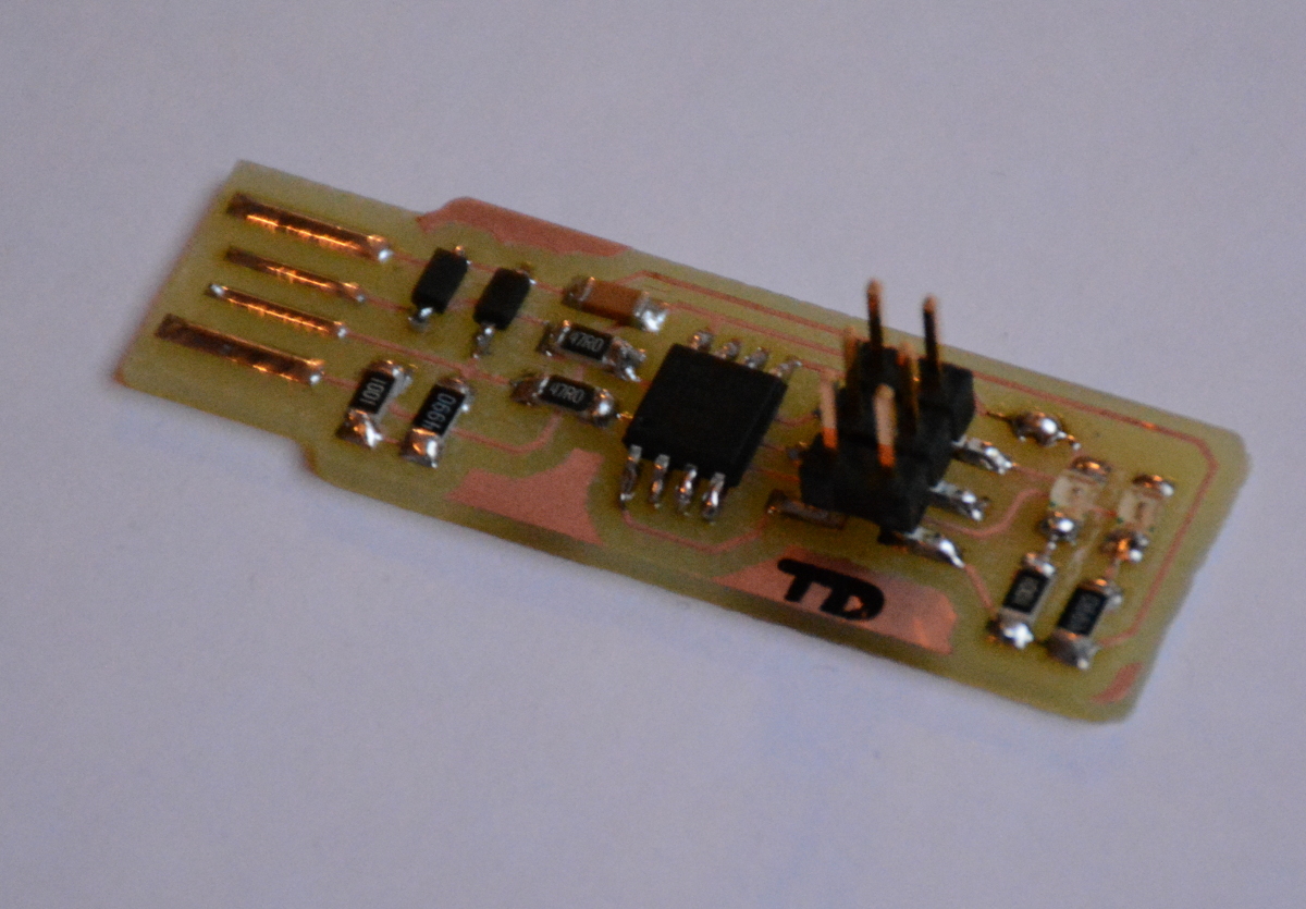
 Some components aren't polarised so you don't have to take care on how to sold it.