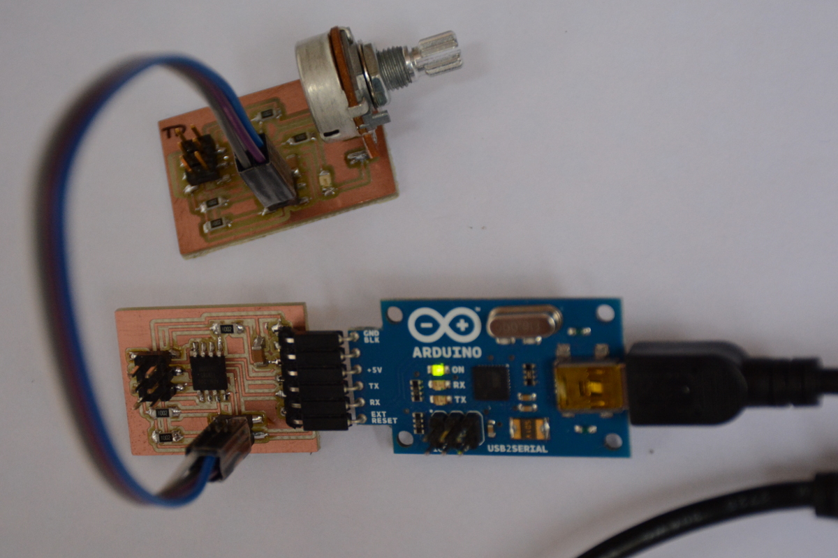
Week 14 : Embedded Networking and Communications
- Design and build a wired &/or wireless network connecting at least two processors
Fab Academy 2018 - Thierry Dassé
For this weekly assignement about network and communication, I have chosen to work on I2C communication.
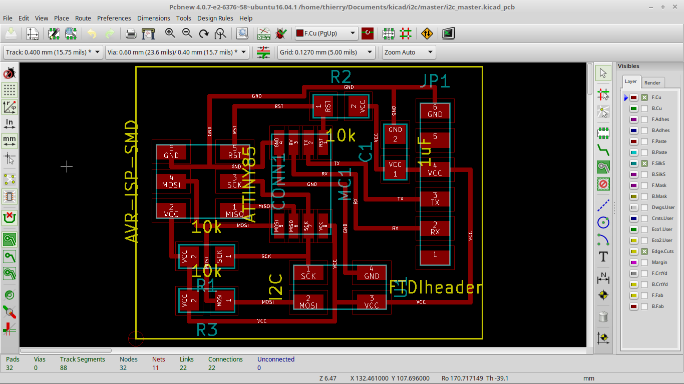
So, I have to make a master board. This board will be able to communicate with a computer through FTDI and with slaves board through I2C.
I also have to make a slave board. This boardwill transmit datas to master board through I2C. On this board, I will add a led and a potentiometer.
I designed the master board on Kicad. I didn't want just to redraw the board example on Neil's lesson to learn how to makes routes between components.
I made my schematics, place my components and try to find how to put all tracks. There are a lot of solutions and each time you make a choice,
it's hard to know if it's a good way or not. At the end, I find a way. It's seems to be correct.
Complete kicad files and png files for milling
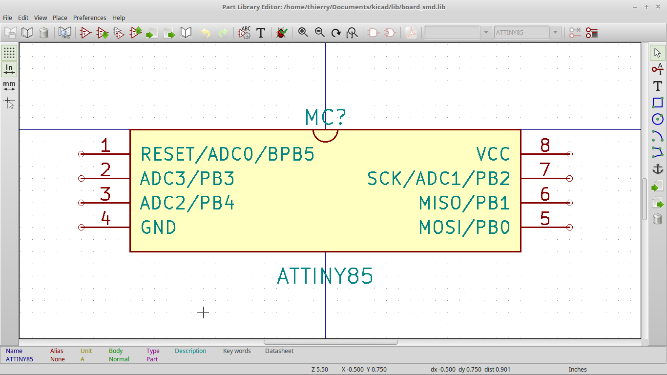
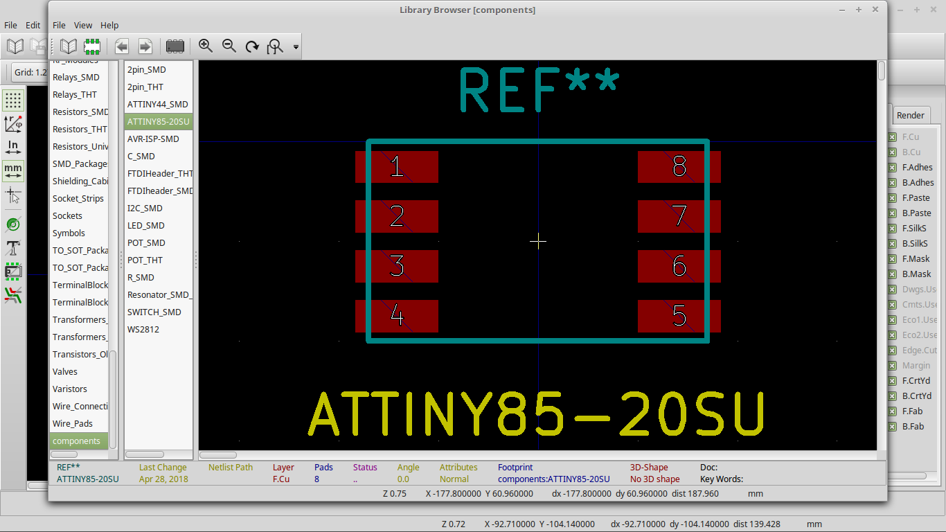
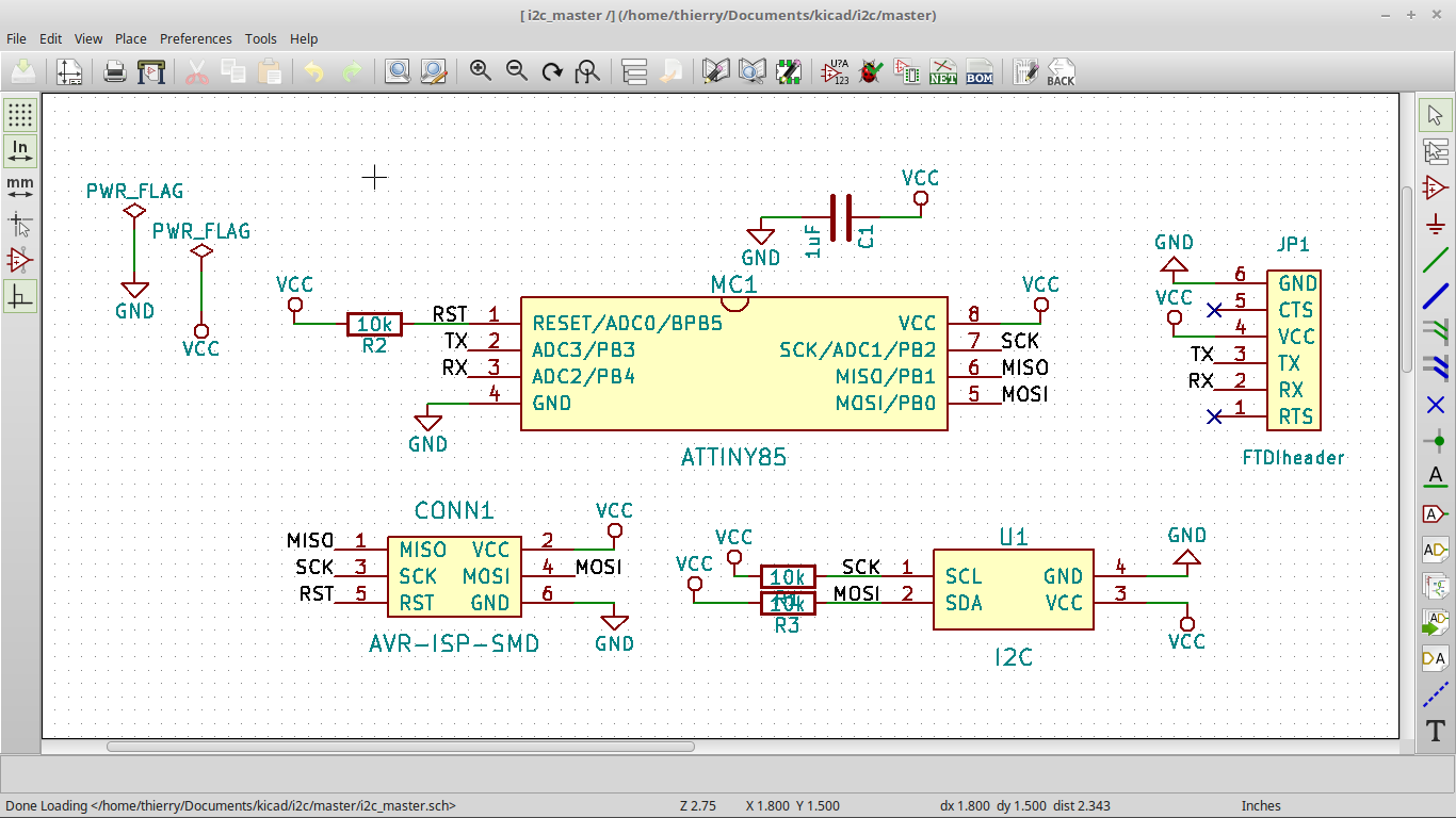
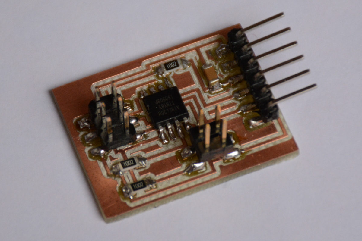
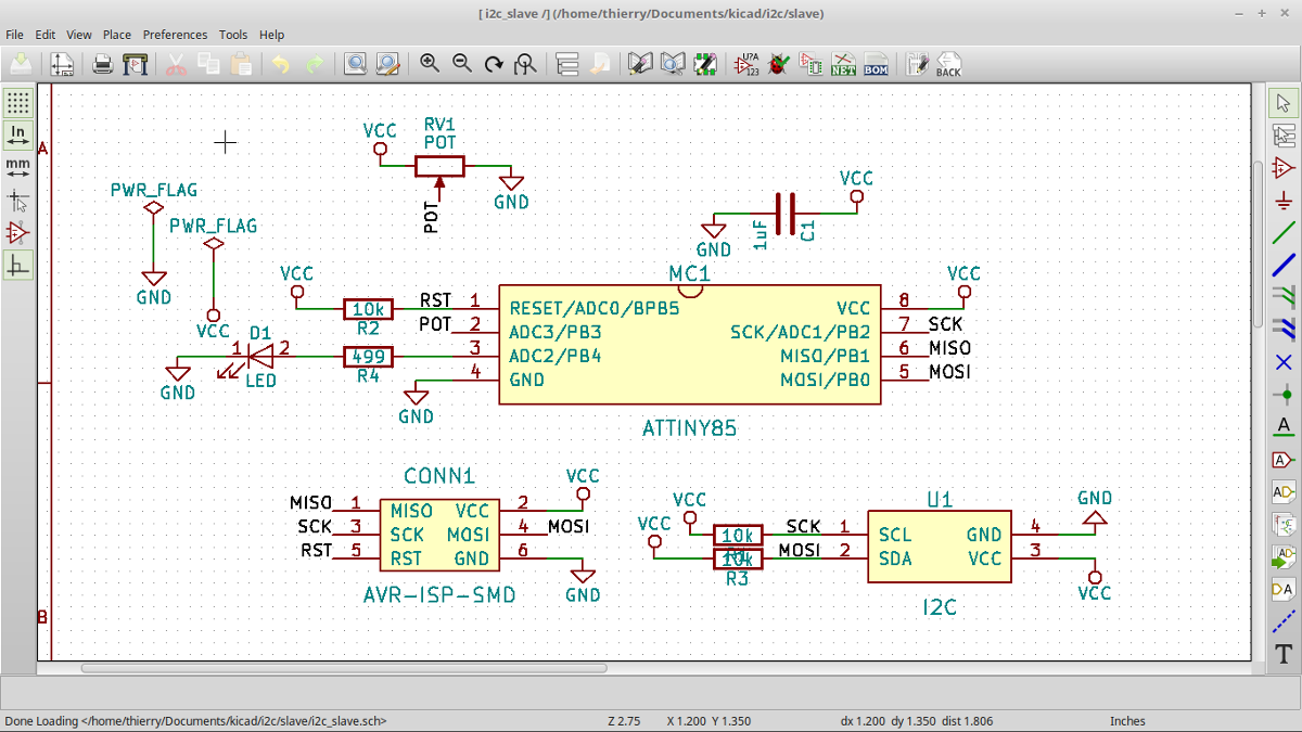
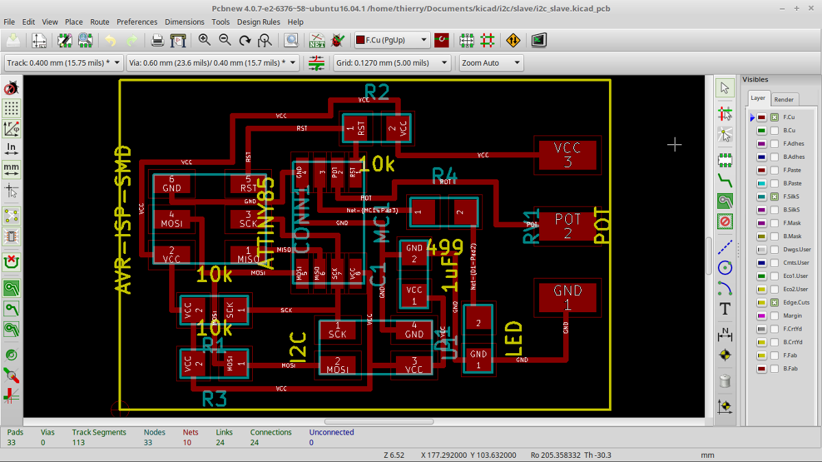
After the master board, I designed the slave board. I put a green led to make tests easier and a potentiometer to have a sensor.
I made the schematic and the PCB inspired by the master except for FTDI (not present in the slave board) and led and potentiometer (only in slave board).
Complete kicad files and png files for milling
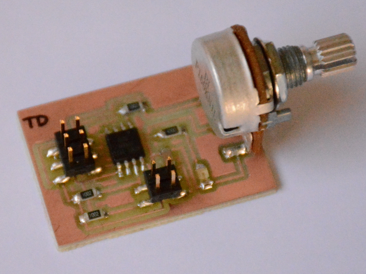
Before making the final program, I made some small test.
I started with test on slave board. I made a program where led is blinking, spped depending on potentiometer state.
I upload my program and it worked well. So, I'm sure that : I can upload a program, led and potentiometer works well.
/*
* slave board
* led and potentiometer test
*/
const int ledPin = 4;
const int potPin = A3;
void setup() {
pinMode(ledPin, OUTPUT);
}
void loop() {
int value = analogRead(potPin);
value = map(value,0,1023,800,60);
digitalWrite(ledPin, HIGH);
delay(value);
digitalWrite(ledPin, LOW);
delay(value);
}
On master board, I made a very simple program to resend characters received by computer separted by a minus. I verified that : I can upload a program and serial communication with computer works well.
/*
* Master board
* serial communication through FTDI test
*/
#include <SoftwareSerial.h>
#define rxPin 3
#define txPin 4
SoftwareSerial serial(rxPin,txPin);
void setup() {
serial.begin(9600);
}
void loop() {
if (serial.available()) {
char com = serial.read();
serial.print("-");
serial.print(com);
}
}
I first search how to communicate with I2C. I found a good page on arduino website : http://playground.arduino.cc/Code/USIi2c
I have downloaded librairies to work with I2C : TinyWireM.zip and TinyWireS.zip
and unziped in folder arduino/librairies.
Then, I made a simple program : the master transmit each character received from FTDI to slave board via I2C and slave blink each time it received a character.
/*
* master board
* send characters received from FTDI to slave board by I2C
* blink frequency can be set by potentiometer
*/
#include <TinyWireM.h>
#include <SoftwareSerial.h>
#define rxPin 3
#define txPin 4
#define I2CDeviceAddr 0x26
SoftwareSerial serial(rxPin,txPin);
void setup() {
TinyWireM.begin();
serial.begin(9600);
}
void loop() {
if (serial.available()) {
char com = serial.read();
serial.print("-");
serial.print(com);
TinyWireM.beginTransmission(I2CDeviceAddr);
TinyWireM.send(com);
TinyWireM.endTransmission();
}
}
/*
* slave board
* blink each time it received a character from I2C
*/
#include <TinyWireS.h>
#define I2CDeviceAddr 0x26
#define ledPin 4
void setup() {
pinMode(ledPin, OUTPUT);
TinyWireS.begin(I2CDeviceAddr);
}
void loop() {
if (TinyWireS.available()) {
char com = TinyWireS.receive();
digitalWrite(ledPin,HIGH);
delay(300);
digitalWrite(ledPin,LOW);
delay(300);
}
}
At the beginning, it didn't worked. After making my master board again, now, master send characters and slave blink when receiving.
