4. Computer Controlled Cutting
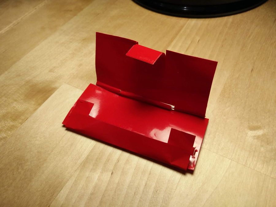
For this project, I wanted to create a small wallet for keeping my metro cards. I worked with Fusion 360 and the vinyl cutter to achieve a parametric design which I could also adapt to the lasercut assignment.
Vinyl Cutting
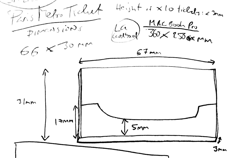
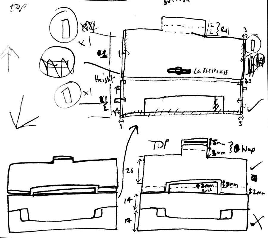
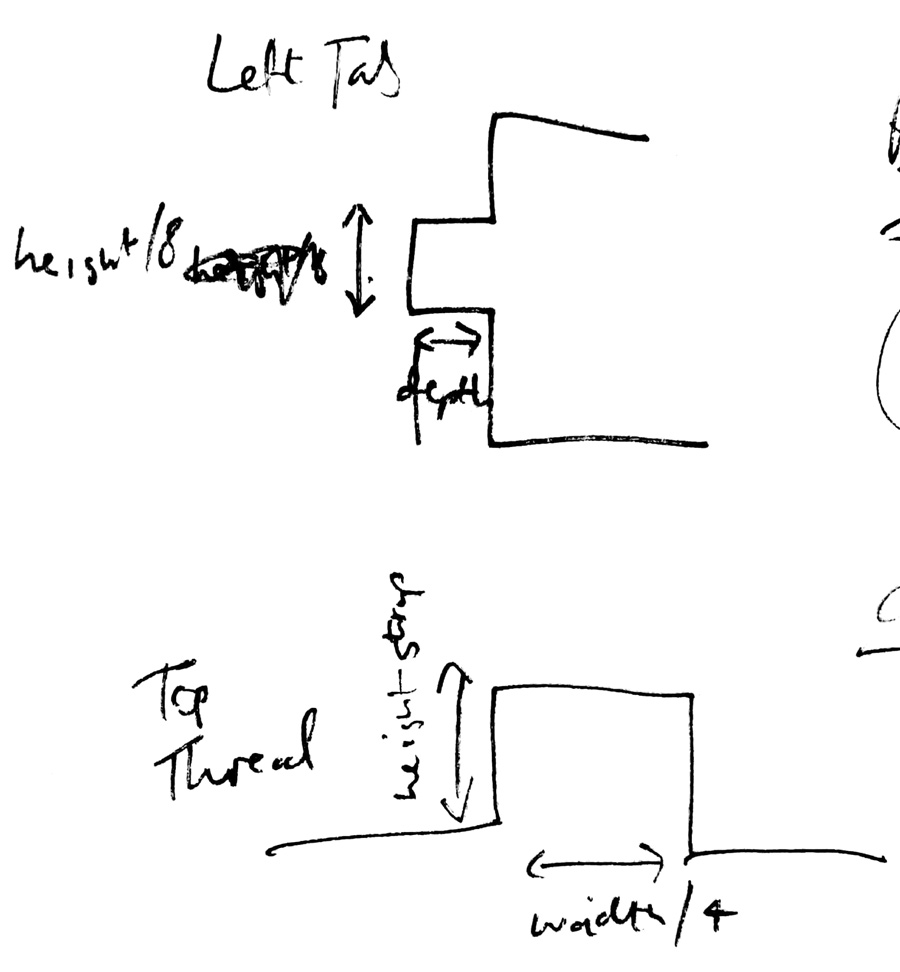
I started the wallet by sketching the dimensions based on a Paris metro card, with appropriate dimensions for a pack of ten (67x31x3mm). I also considered an XL version of the wallet to hold a macbook pro (360x250mm). As with any creative project, it helped enormously to work measurements and angles out on paper, particularly as extra material was required for tabs and to roll around the hinge. I knew that one side of the vinyl was sticky, so I was going to have to duplicate material for interior and exterior.
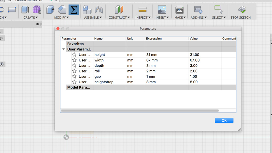
I added dimensions in Fusion, creating relevant names for the top (holster) and bottom (cover) parts. I based the shape of the cover on the holster body.
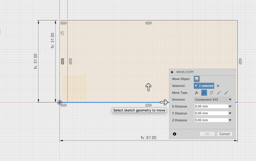
I positioned rectangles using these dimensions and used a combination of rectangles and extrude (cut) to create the necessary gaps in the structure. I found this an issue later on as line work for these cuts was included in the dxf export.
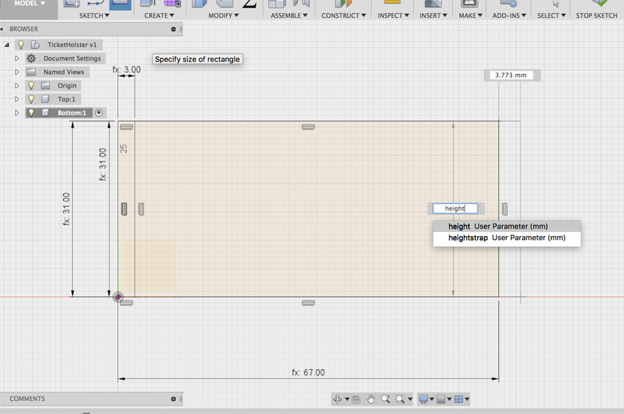
I positioned rectangles using these dimensions and used a combination of rectangles and extrude (cut) to create the necessary gaps in the structure. I found this an issue later on as line work for these cuts was included in the dxf export.
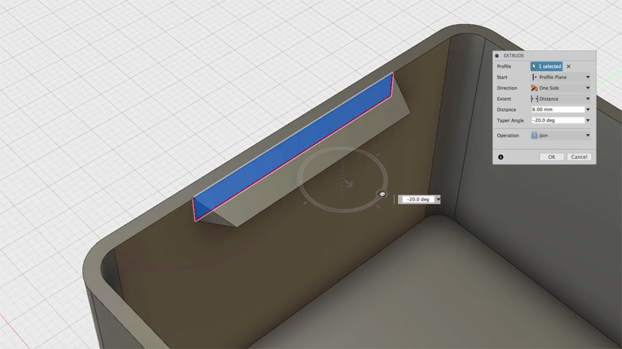
Duplicating/copying & pasting became an issue as I tried to share object with other files and keep their parameters. For example, I wanted to create a second version of the wallet in XL. I watched a couple a tutorials (1 and 2) but I still find this challenging. Maybe its something to do with branches as in Git?
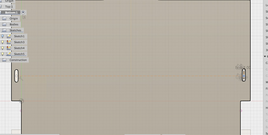
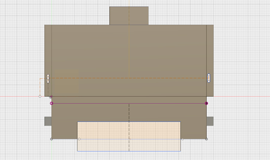
I created slots on the sides of the holster to connect the walls around the metro card. I had some challenges duplicating slots these slots and ended up having to recreate them on the other side.
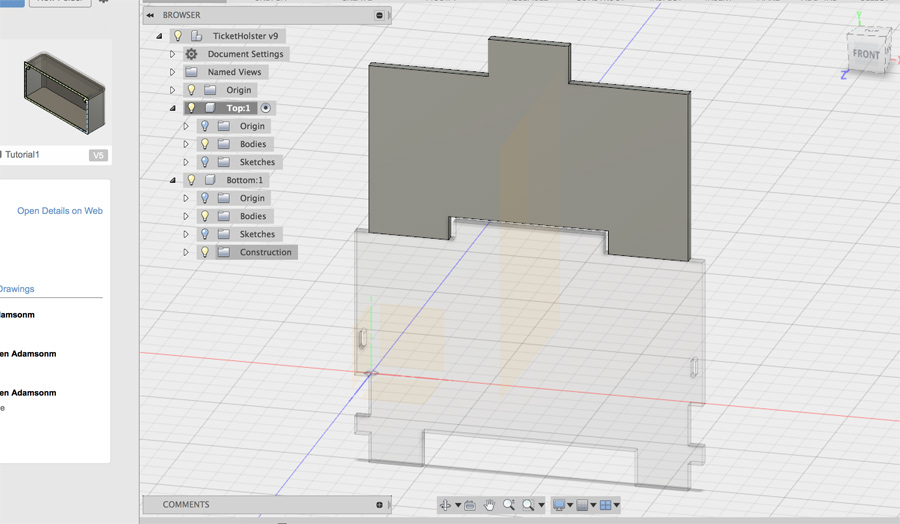
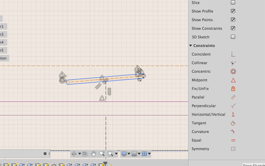
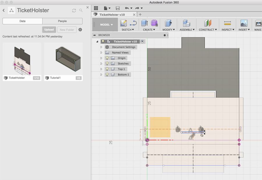
The use of a mid-plane that I had used successfully in a previous tutorial didn't work with my design. Slots very easily go off angle if you select the wrong part and then it is tends to try to snap to the new angle.
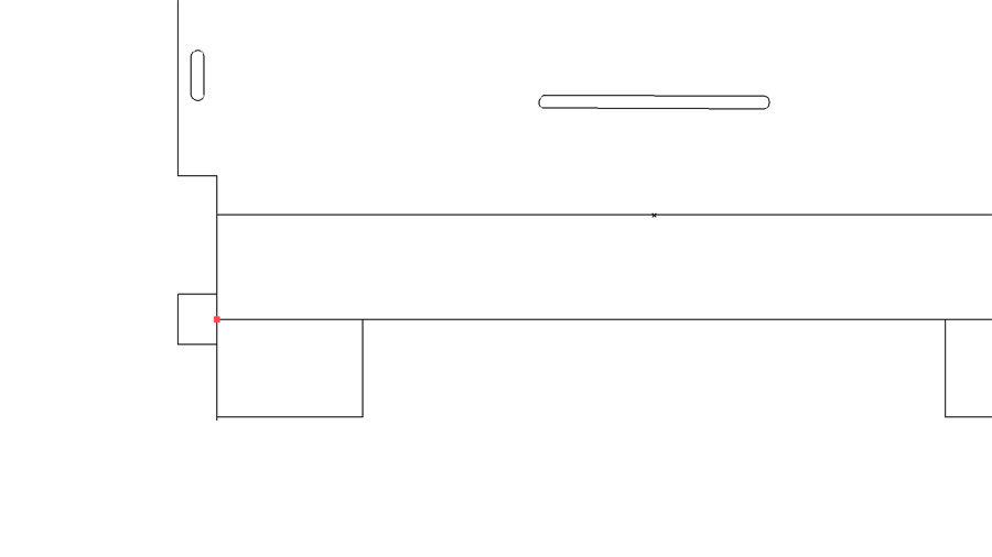
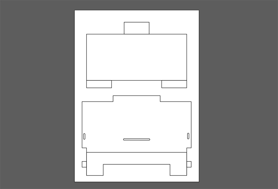
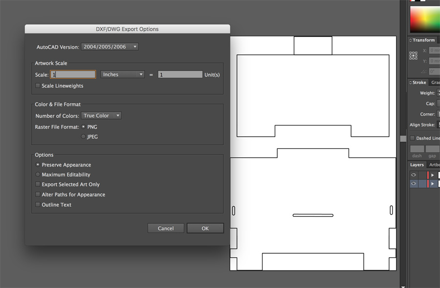
I exported my two sketches for the two parts as dxf files. These opened easily in Illustrator but there where I had to do quite a bit of cleaning up. I removed the linework present from cut-out shapes on both the cover and holster. I combined my drawing into one file and exported it as a dxf again.
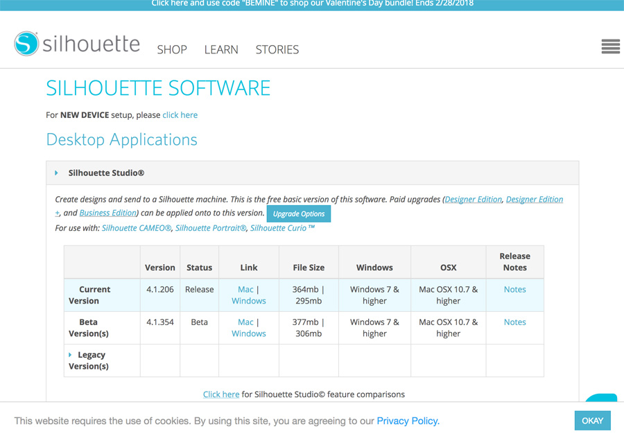
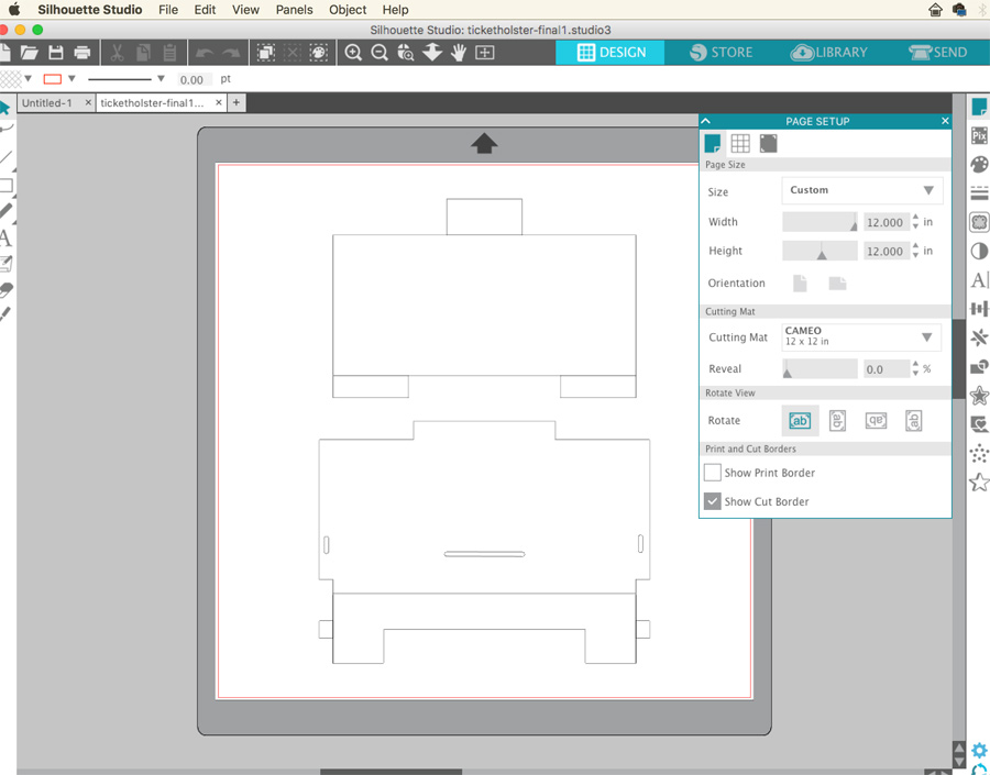
I downloaded Silhouette Studios from the Silhouette website and imported my dxf. My drawing appeared scaled across the machine preview and I had to figure out a way to reduce the size.
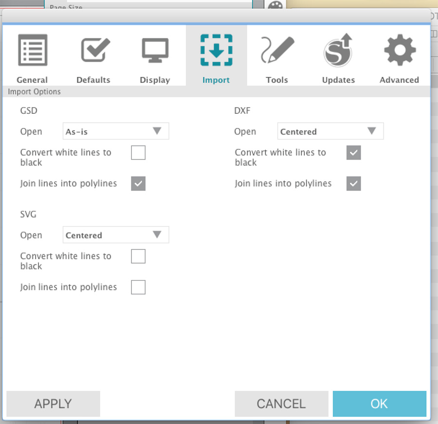
I compared the size of the print area and also adjusted the settings under Edit > Preferences > Import.
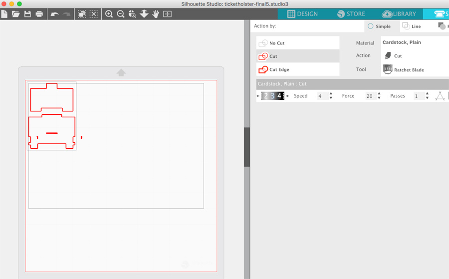
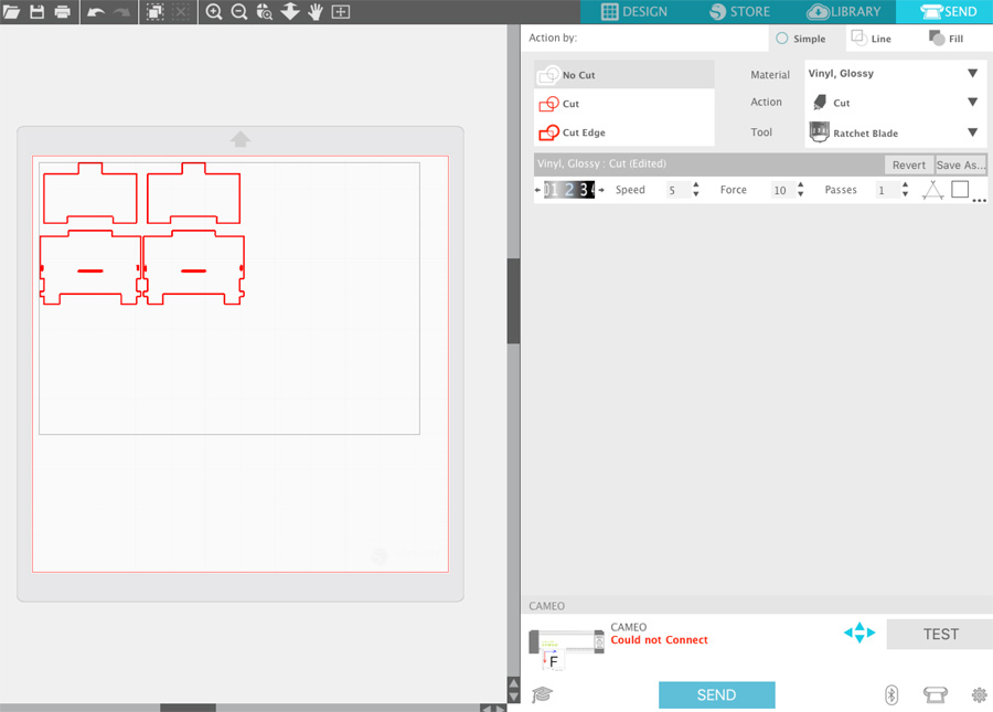
In the end, I realised that the cutting plate was 12 inches squared and that Illustrators export dimensions should be set to reflect one inch to one unit.
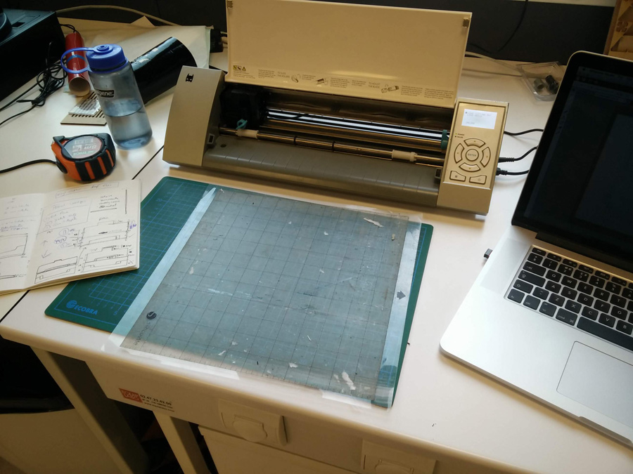
With the appropriate scale ready, I fed the edge of the vinyl into the machine and pressed 'enter' to start the feed.
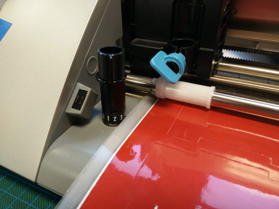
Some adjustments had to be made after the first cut – This is a manual process – You must take the cutter out of the machine and use the 'bottle opener' hole on the bed to change the number. You then adjust it to match on the software.
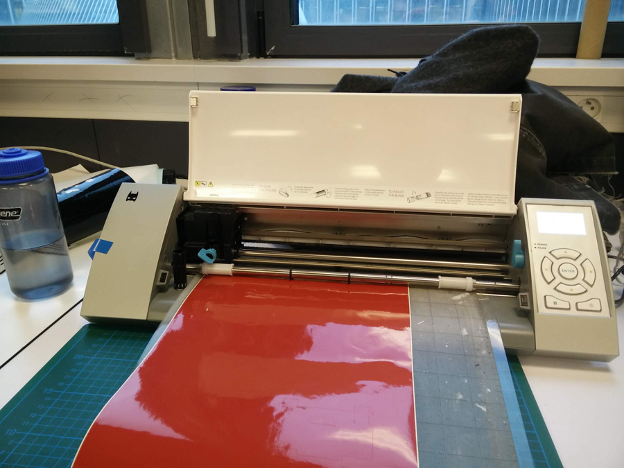
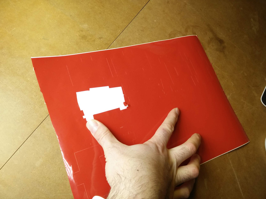
I started with '2' which didn't cut. When it did cut (on '3') the material moved around, causing a warped shape on the cover. I then used glue spray to hold it on the cutter sheet.
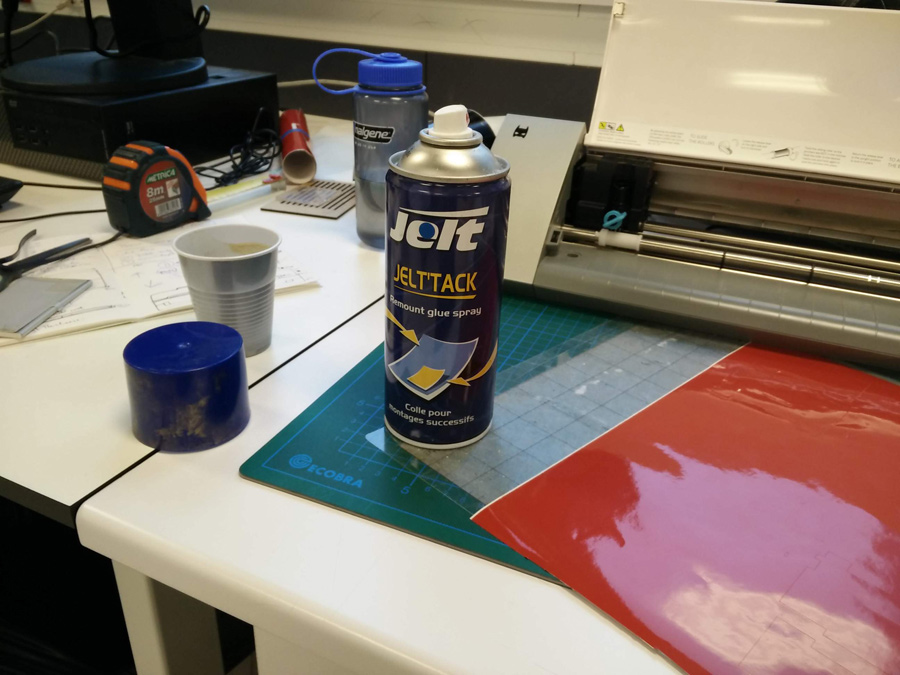
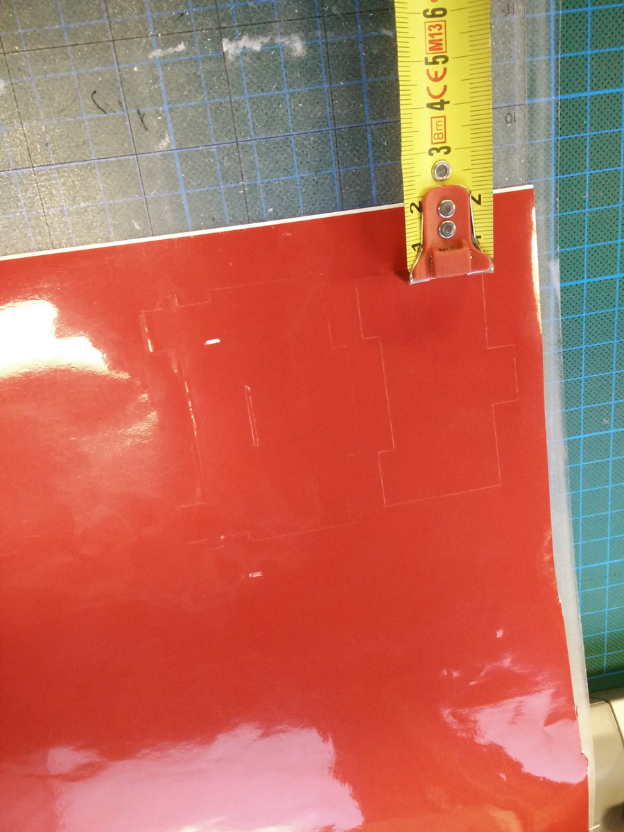
I defined a rough border of 20cm because I didn't want the cut right on the edge of the vinyl where it is more likely to break.
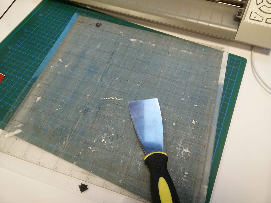
With the '3' cutting well, I used wall scraper to remove the vinyl from the cutting sheet.
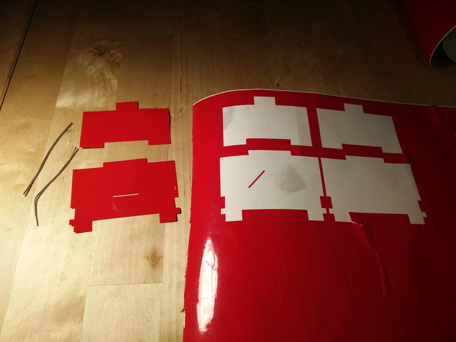
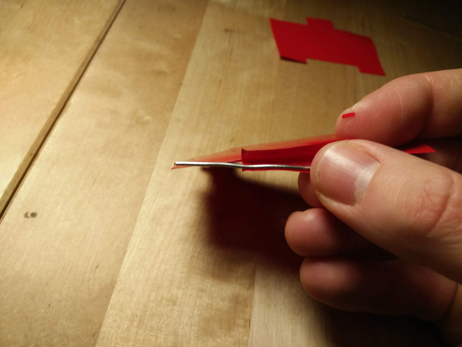
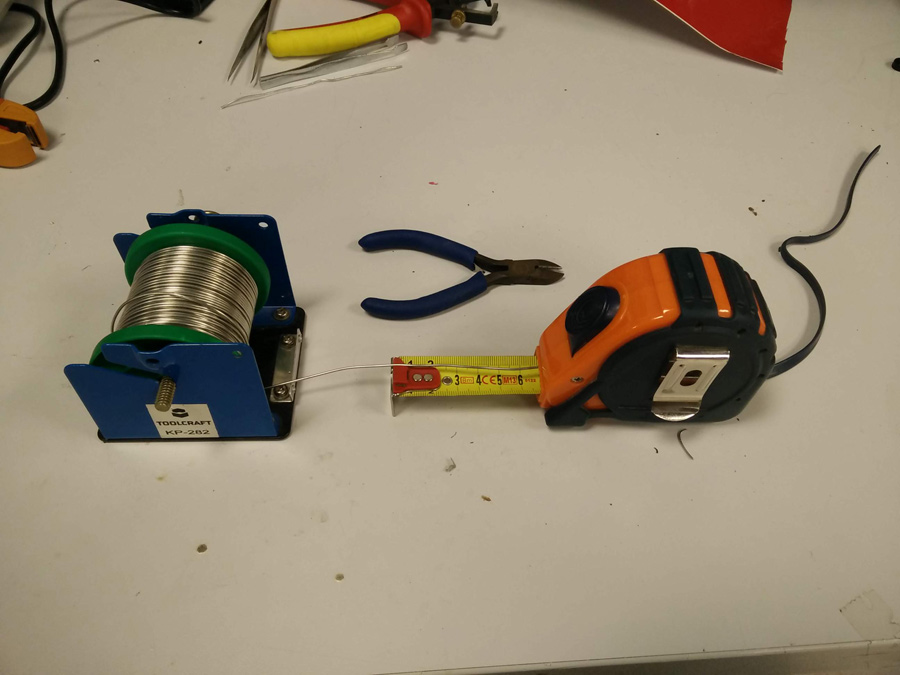
At this point my intention was to use a thin but solid wire for the hinge to work around. This wasn't available at the time, so I cut a length of soldering wire (tin, 67mm) instead. With all the necessary parts together, I started assembly, sticking the matching faces of the vinyl togther.
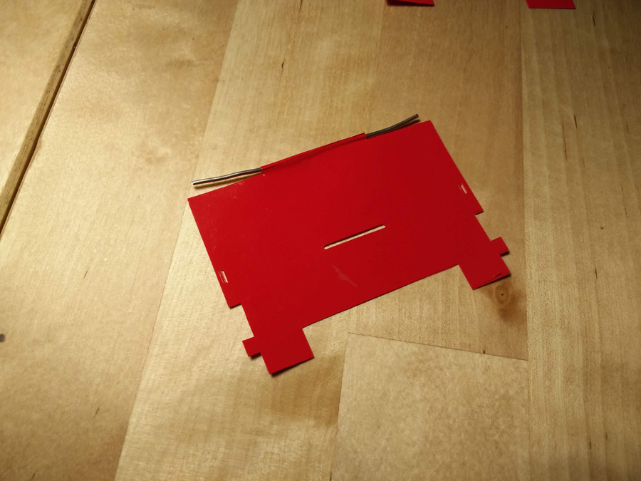
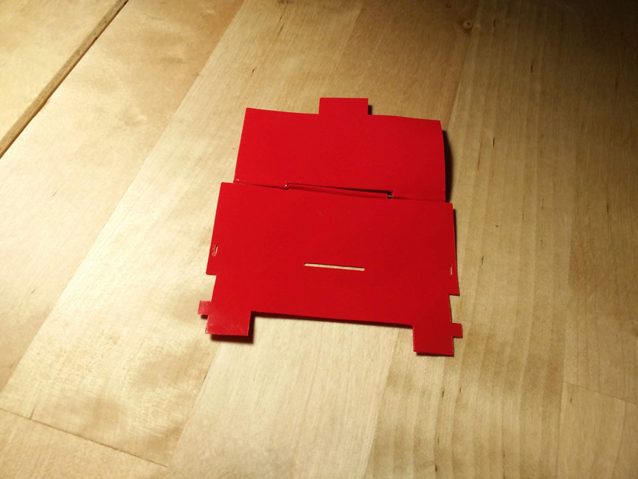
I folded the right and left tabs into the slots – They didn't match and probably should have been designed in a 'T' shape to properly grip the outer vinyl.
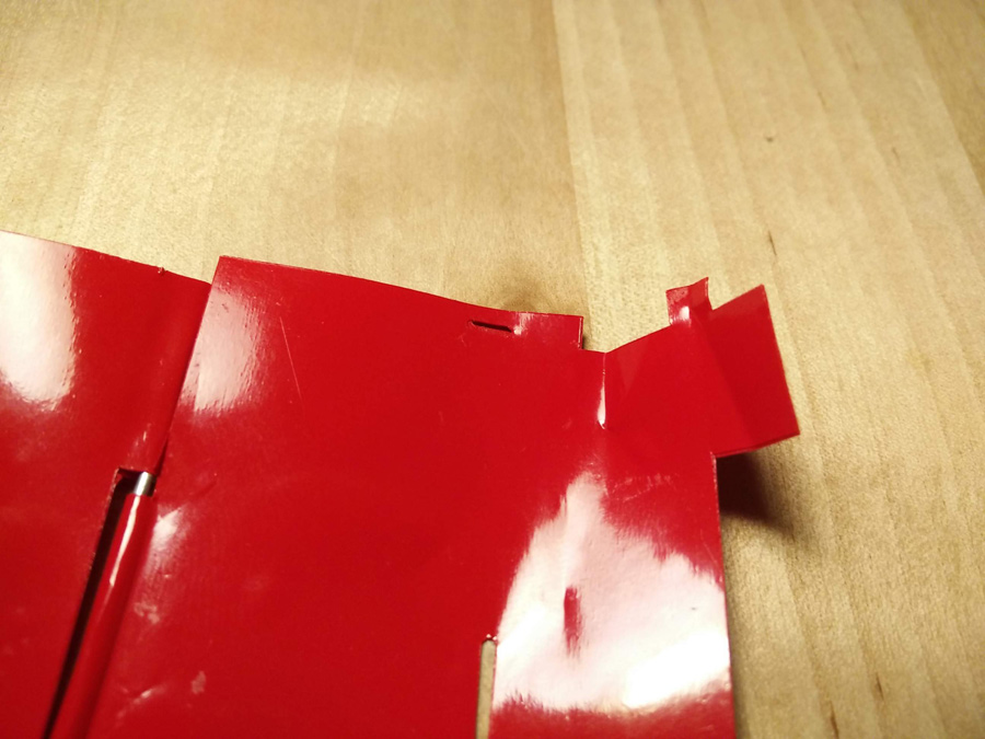
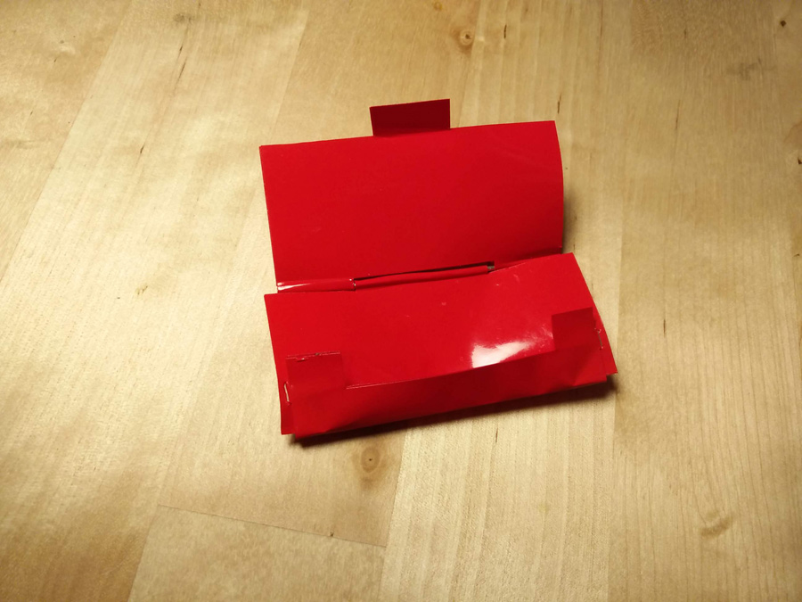
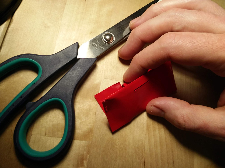
For the file tab (cover, to close the wallet), I had to cut the material to make it longer. Again, a revision of dimensions would be necessary here.
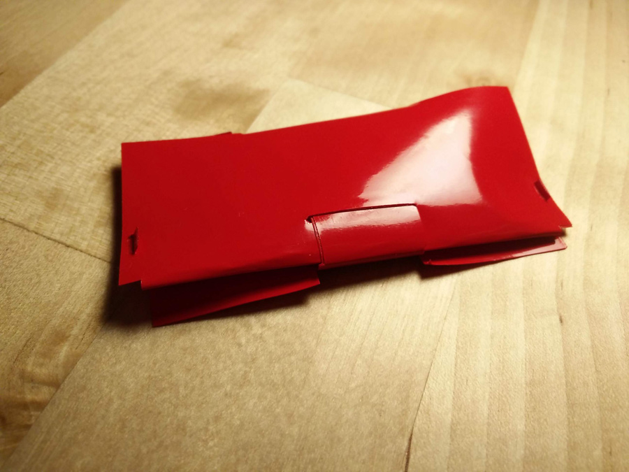

From the back, the wallet looks pretty smart. And with a little scotch on the sides, it fits a pack of 10 metro cards.
Laser Cutting
Group Project
Information on our lasercut testing is available on the group page
Solo work: Cardboard
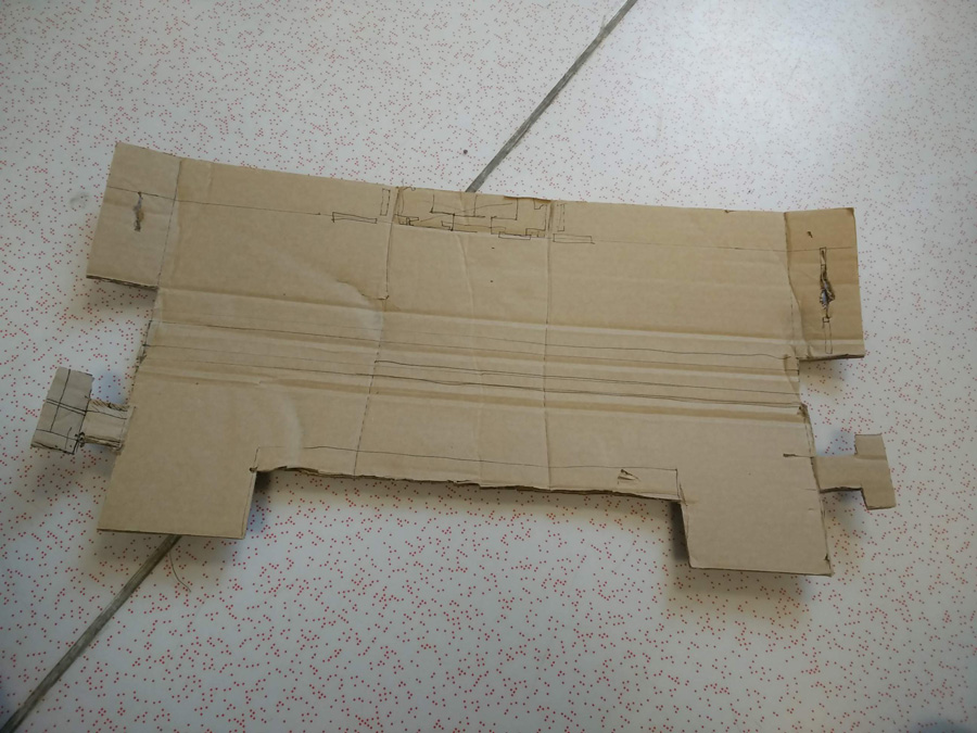
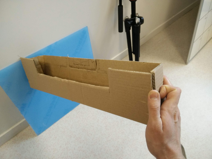
My initial concept was to reuse the parametric dimensions of the wallet on a larger scale, to form multi-purpose box. My initial test was using a piece of cardboard (600x300mm) to assemble a box in two different directions. Using scissors, I cut holes and grips to see how it might look. On the horizontal axis, the box is quite low for storage. On the vertical, with many large openings, the box might serve better as a lantern.
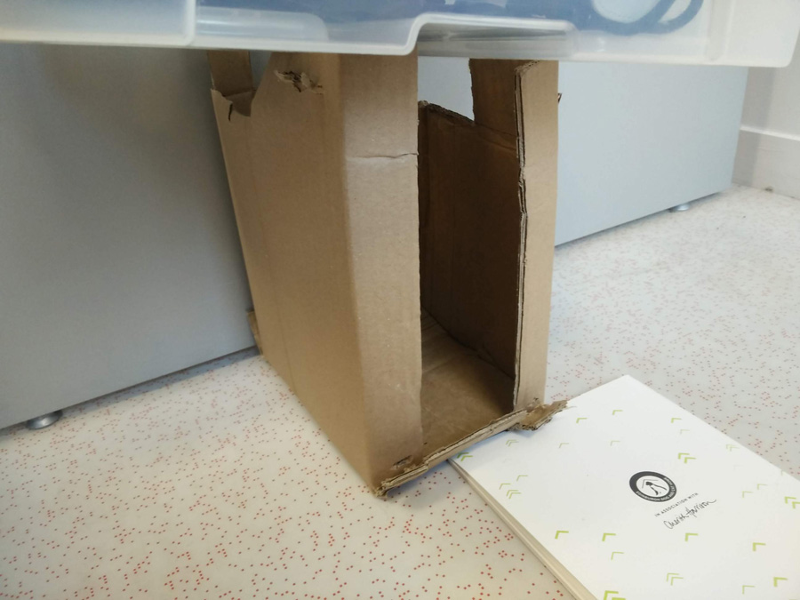
Solo work: Acrylic
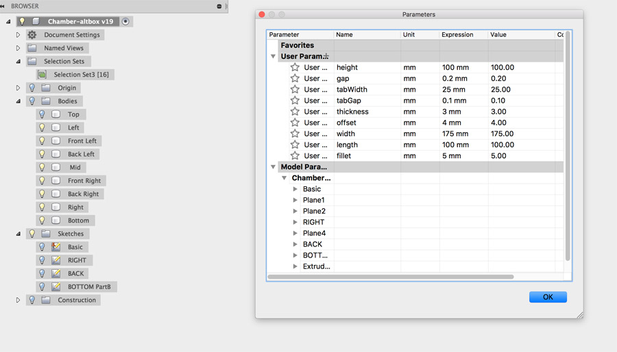
I returned to this assignment after several weeks of learning Fusion and improving my parametric design. In week 15 and 16, I worked on a chamber for our roto-casting machine and I decided to base my press-fit construction kit on this.
I worked in Fusion 360 to edit the parameters of the chamber to a different size.
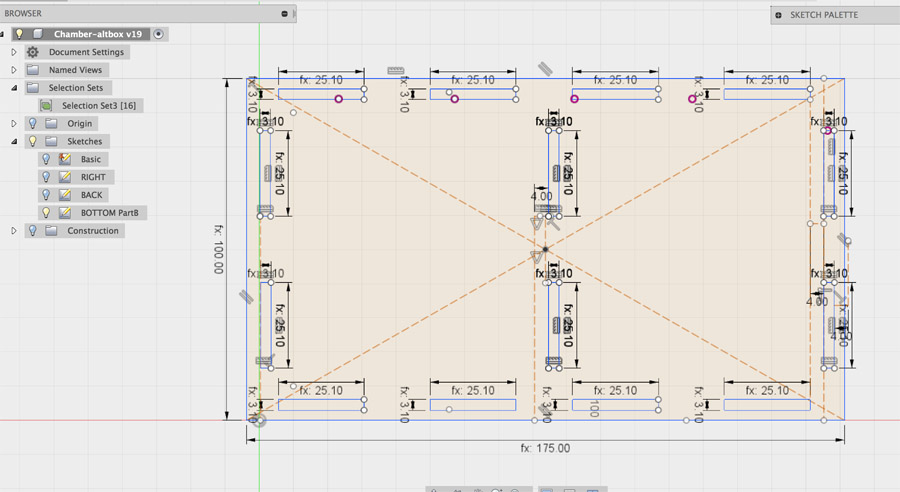
I added different parameters together to allow for tolerance between tabs, ie. tabWidth (25mm) plus tabGap (0.1mm). I assembled tabs so that I could create two separate cambers within the same construction.
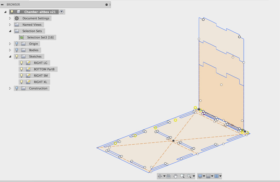
Finally in order to make the construction kit adaptive, I added two pieces with longer and shorter height than the standard square 100x100mm panels - This would create a kind of sloped roof.
From here, I made a duplicate of the Fusion design (under a folder 'production') and set to work removing any elements that wouldn't be cut – Bodies and construction lines specifically. The sketches were then exported as separate DXF.
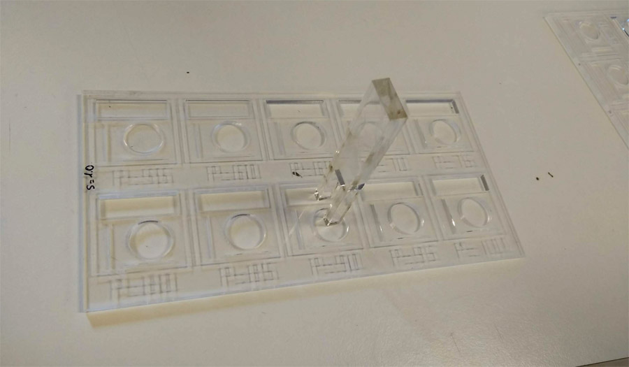
I referred to the 3mm acrylic test we had done as a group. At a speed of 1.0, the lasercutter cut through at a power of 90.
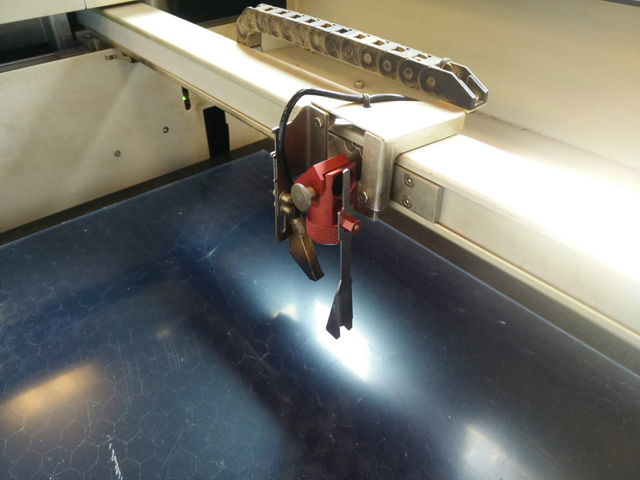
I loaded the acrylic into the Trotec laser cutter and aligned the z-axis using the alignment tool and pressing the up button gently. The tool is places hanging vertically from the side of the laser optic. When the tool falls, the laser is aligned.
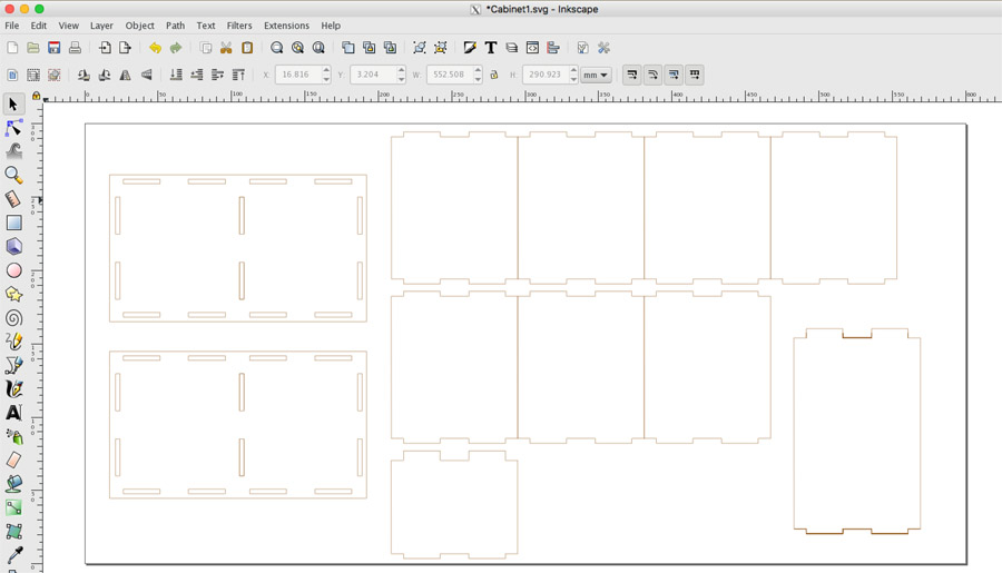
I loaded the DXF into Inkscape and layed them out on a 600x300mm file. I selected all files and applied a 1px stroke, without a fill.
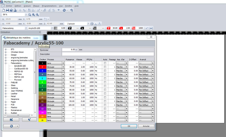
In Trotec Job Control, under the 'Programmations' menu, I selected 'configuration materiaux'. We had created specific profiles for different materials. Under 'Acrylic 55-100', I chose the colour associated to a power of 90 (brown – R 153, V 102, B 51), I adjusted its speed to 1.0.
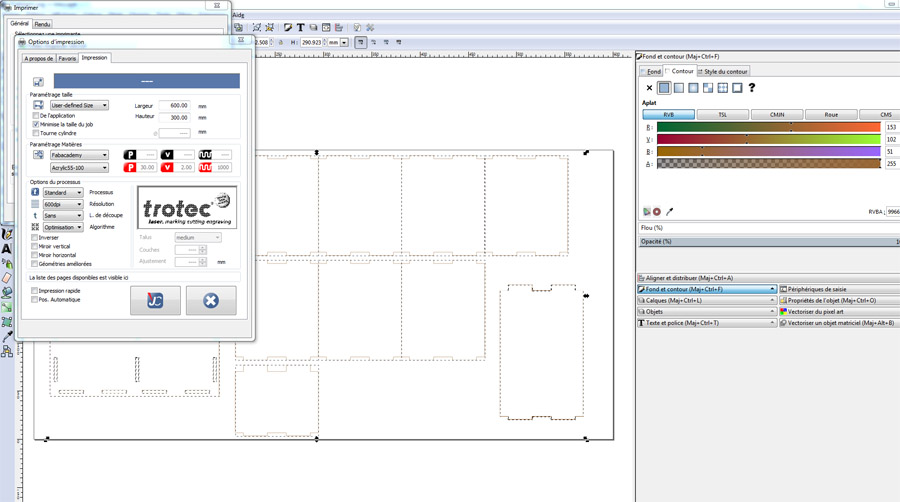
Back in Inkscape I then selected File > Print and went into the settings. Under 'Parameters Materiaux', I selected 'Acrylic 55-100' once more and hit the JC button.
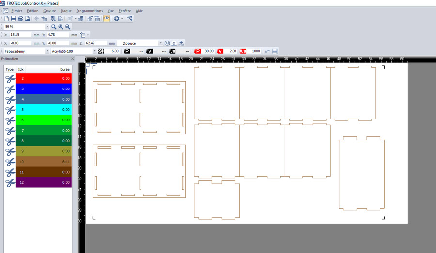
The file to be cut loads in the right-hand panel. Load by dragging or double-clicking on the file. The brown stroke is referenced as the only job where cutting time is registered (6:11). I then ran the job.
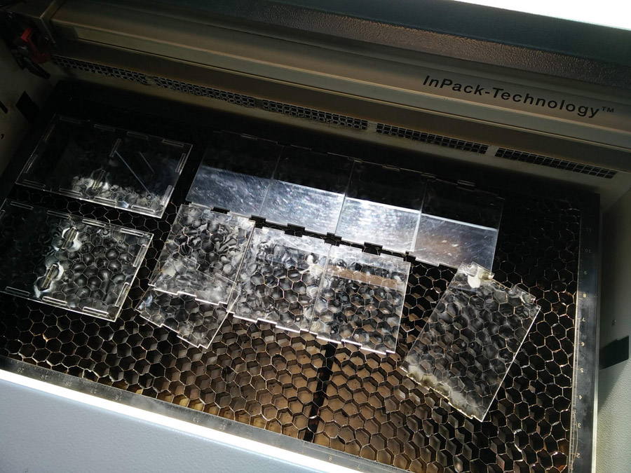
The file cut well, although it burnt in several places. In hindsight, I should have left the plastic wrap on the acrylic to reduce this risk.
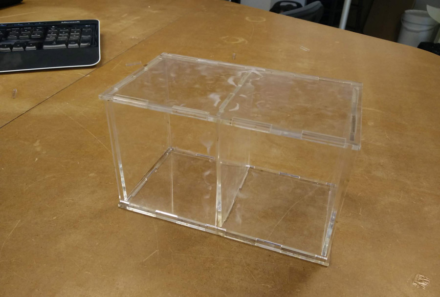
I then assembled the kit one of two ways – As a box used to store small items.
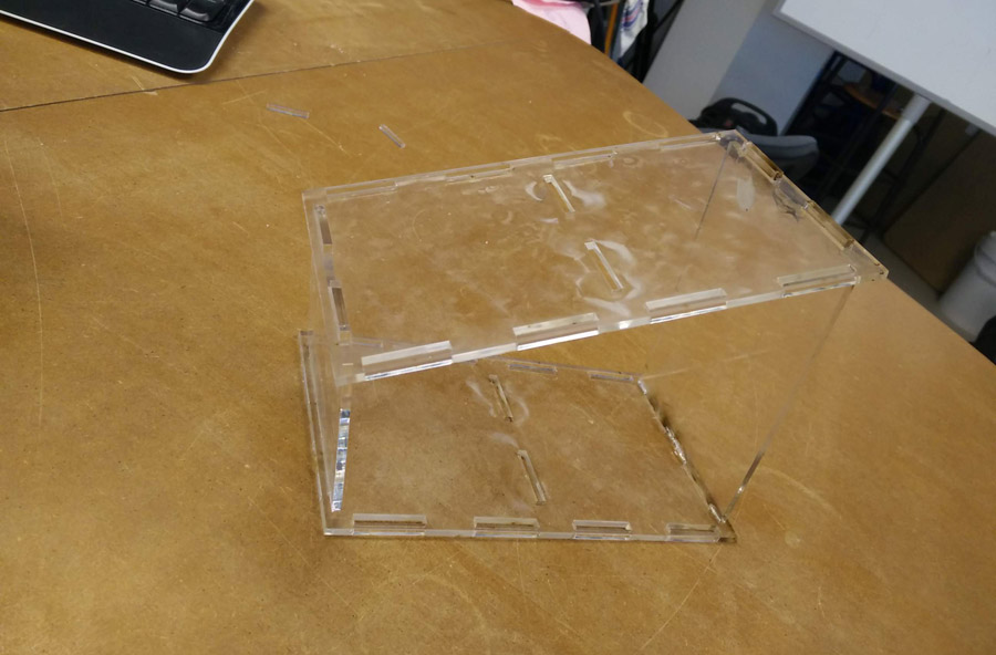
And as an (open) sloped roof – This could easily be used to support books, mobile phones etc.
Back to the top