Electronic Design (Group Project)
this week assignement are:
- Design a machine (mechanism + actuation + automation), including the end effector, build the passive parts and operate it manually.
rotocasting machine
This week we decide to work on a rotomoulding machine.
The electronics part
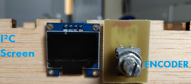
for the electronics i decide to make our own board. for that we will connect 3 things.- One screen in I²C
- One encoder + button
- One stepper motor.
 for using the screen in I²C we werent able to make it work on an attiny 44. so it was time to make our own ARDUINO LIKE.
so i based my design into the SATCHAKIT MICRO but i add a 12V regulator circuit for giving enough power to the NEMA17, i made the pinout for the A4988 and all the connection needed. add some voltage entrance, and redesign the pinout for what i need. i change everything for beeing able to made it in CMS.
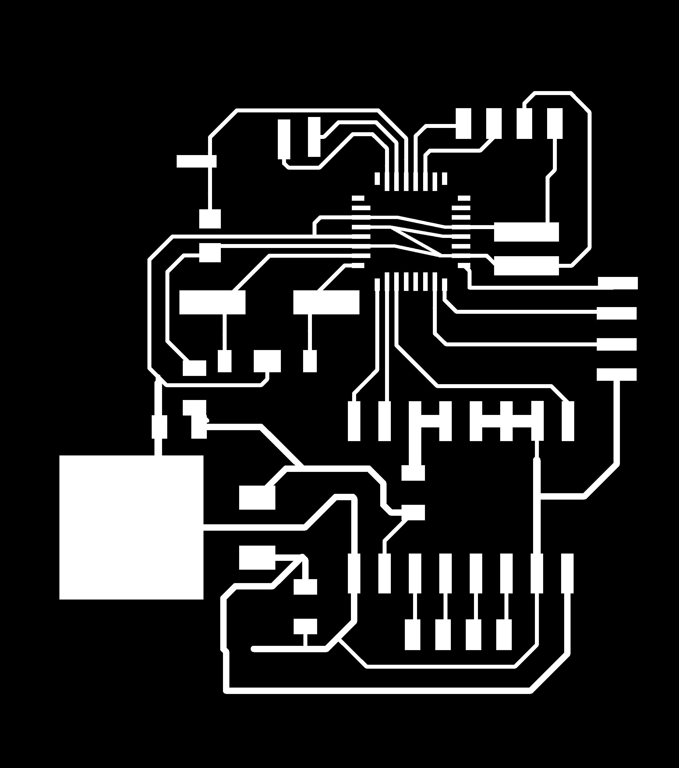
EAGLE design
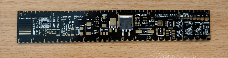
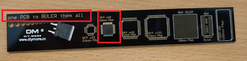
i started by looking what part we have in the lab. so we having 7805 in smd package. but the format of the package wasn't write on it. hopefully i received few days before: a ruler with the size of different packaging .gain so much time, i was able to find the good library for the D2PAK aka TO 263
Milling
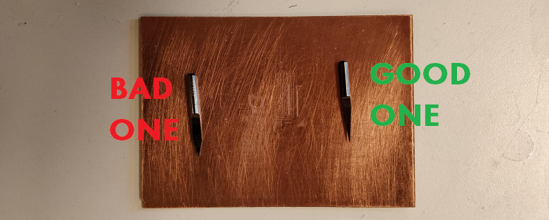
The milling part was the hardest.I had to mill the QF32 ATMEGA328 with an 0.1 "V shape mill" with 20° angle. but it was to whide for beeing able to solder it. or it wasn't cutting deep enough.. the time to receive the good bit i made So much test. and was almost satisfy of the result. but i wasn't able to Reproduce the result mutliple time, for the simple reason that a pcb sheet is never perfectly flat. and with a V bit we can feel it!
the good & bad V bits
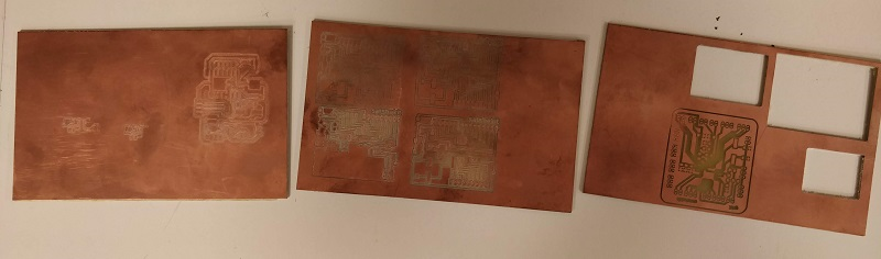
 Here you can see a part of many test i made:
So monday we received the good bit. and i was able to mill the board with a V shape Mill but a 10° this time. and it was perfect the first time. i was really happy of the result. and Monday night i tried to solder an ATMEGA328, in the crappy board i already made. the idea was to be able to see the result on the binocular. and learn how to solder.
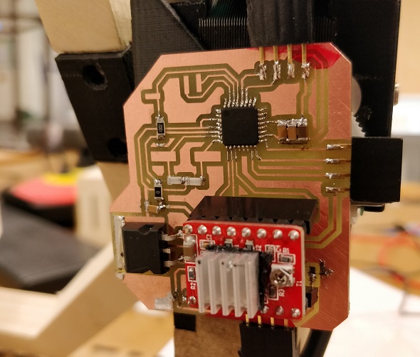
After this test i learned a lot about how to solder a QFP32. so i decide make my final board. i started by soldering the 7805 Regulator Package to the board. like that i was able to see if i had the perfect 12v transform in 5 volt before making anyother mistake.
so that worked fine. so i decide to solder a Atmega328 slowly on the final board. pretty hard but doable. we ar using QFP32 0.8 package. i can't imagine soldering by hand a QFP32 0.5
 I used Nail polish for protecting some part of the pcb where i some component are overlaying some path of the pcb.
When that done i started to solder everything, and test the path with my multimeter! everything looked fine. so it was time to upload the programm.
I used Nail polish for protecting some part of the pcb where i some component are overlaying some path of the pcb.
When that done i started to solder everything, and test the path with my multimeter! everything looked fine. so it was time to upload the programm.
Uploading some code
so for uploading the code i checked on the satshakit micro documentation in github pretty simple like an attiny44, we had to connect the isp pinout into an AVR MKII- 13 to 13
- 12 to 12
- 11 to 11
- 10 to reset
- 5V to VCC
- GND to GND
and after that we have to burn the bootlader into our board
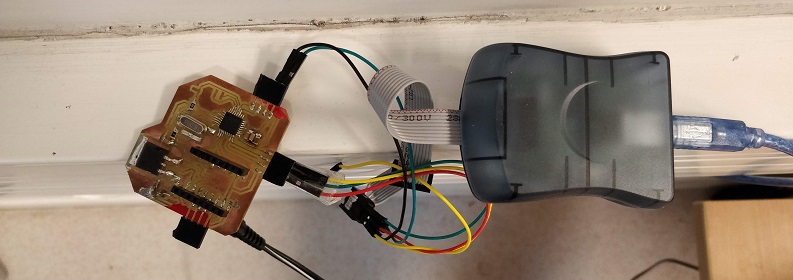 ET VOILAA!
--
ET VOILAA!
--
file of the week.
here you'll find the file of the week
For downloading
right click and save as
- outline file (png file)
- eagle file schematic file
- Eagle File board file
- library For D2PAK / TO 263 (lbr file)