Exercise 07 - Computer-controlled machining
Requirement
Make something big using a CNC machine.
Testing for fit
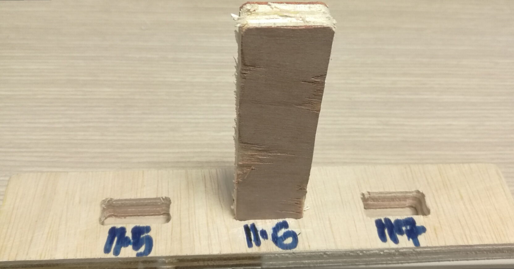
This week, for the group assignment, we are require to test on the CNC setting. Kerf is the width of material that the process removes as it cuts through the plate. The CNC routerused is SK2020, the dimension of plywood used was 8 x 4. The thickness is 11.6mm. Based on the thickness of the material, the tested slot with various settings 11.7mm, 11.6mm and 11.5mm. 11.6mm gave the best fit.
| 11.7mm | slight movement when more force applied on the test piece |
| 11.6mm | best fit |
| 11.5mm | encounter a little bit of resistance while pushing in the test piece |
Below are the settings that need to be take note of;
Chip load
The thickness of a chip which is formed during the machining of materials. chipload is critical as the chip is the proper size, the chip will carry away the heat promoting long tool life. If the chip is too small, causing prematurely dulling. Too high of a chipload will cause an unsatisfactory edge finish, or part movement.The formula to calculate chipload is: Feedrate / (RPM x # of flutes)
| To increase chip load | Increase the feedrate | Decrease the RPM | Use less flutes |
| To decrease chip load | Increase the feedrate | increase the RPM | Use more flutes |
Surface cutting speed (Vc)
This is the speed at which each tooth cuts through the material as the tool spins. Typical values for cutting speed are 10m/min to 60m/min for some steels, and 100m/min and 600m/min for aluminum. This should not be confused with the feed rate. This value is also known as "tangential velocity."Spindle speed (S)
This is the rotation speed of the tool, and is measured in revolutions per minute (rpm).Diameter of the tool (D)
The size of the bit that is using.Number of teeth (z)
This is the distance the material is fed into the cutter as each tooth rotates. This value is the size of the deepest cut the tooth will make.Feed rate (F)
The speed at which the material is fed into the cutter.CNC Routing Process (S)
Step: Creat the sketch over fusion 360 and saved the file as dxf.
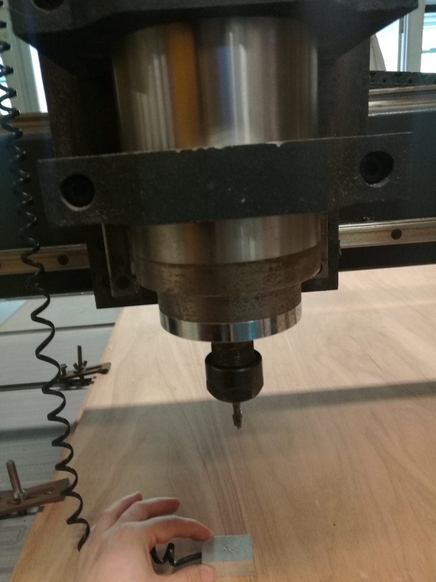
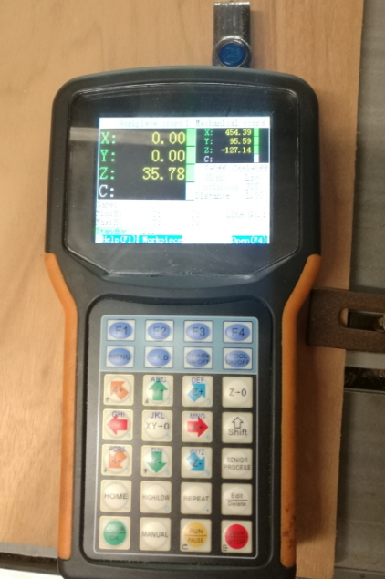
 Step2: Zero setting.
When lowevering the bit, on the controller, using C.A.M button, this is lowever the bit as slow motion, once it touches the zero block, it will automatically move upwards. the Z setting in this case is 35.78.
 Step3: On the CNC machine, open the software Vision Numeric
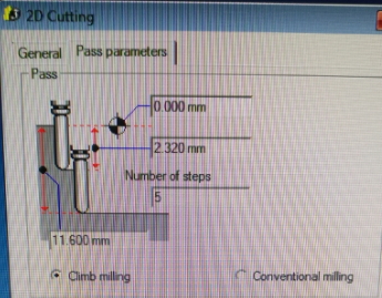
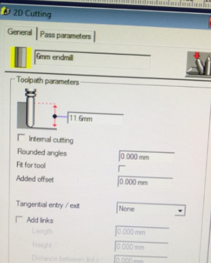
Import File - cam module - create toothpath -2D cutting-compute all layer
I set the no. of steps to be 5 and the cutting depth is 2.32mm to cut through my 11.6mm thickness.
 Step 4: generate .U00 file and converted to gcode.
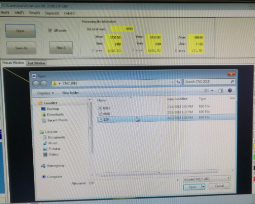 step 5: open the U00 file on software call CNC-CHANGE, selects Filter Z which helps to minimised the Z to move up and downs. Saved as JG file. The JG file recognised by CNC machine.
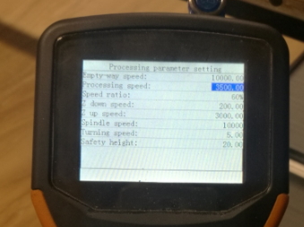
Step 6: On the CNC controller, i am trying up on different processing speeds OF 1000, 3500 and 10000. I found out that 3500 gives me the optimal cutting results.
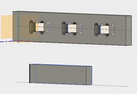
Simple Laptop holder
I decided to do something simple and something i can use, thus Laptop holder since to be the one.
the measurement i have for my design as per following:
Top: Length (500mm) x width (240mm)
Side 1 + 2 : width (240mm) x height (150mm)
To be continue, CNC machine at fault.
Download
You can set up a button for files to be downloaded with:
	<a href="#">
	<button type="button" class="btn btn-primary btn-lg">Download the file</button>
	</a>
Result:
Would you like to insert more style/elements?
Check the documentation of Bootstrap here.