
Input Devices
Magnetic Sensor
For this assignment I decided to build an electronic board equipped with a magnetic sensor that can detect magnetic fields.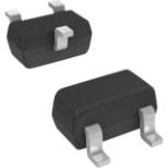
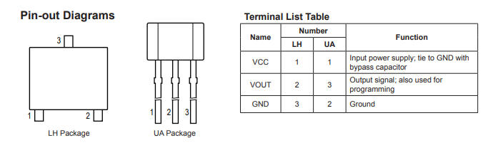
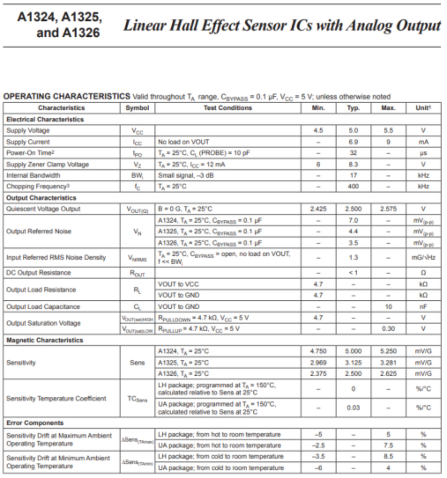
DataSheet
This is the datasheet of the magnetic sensor.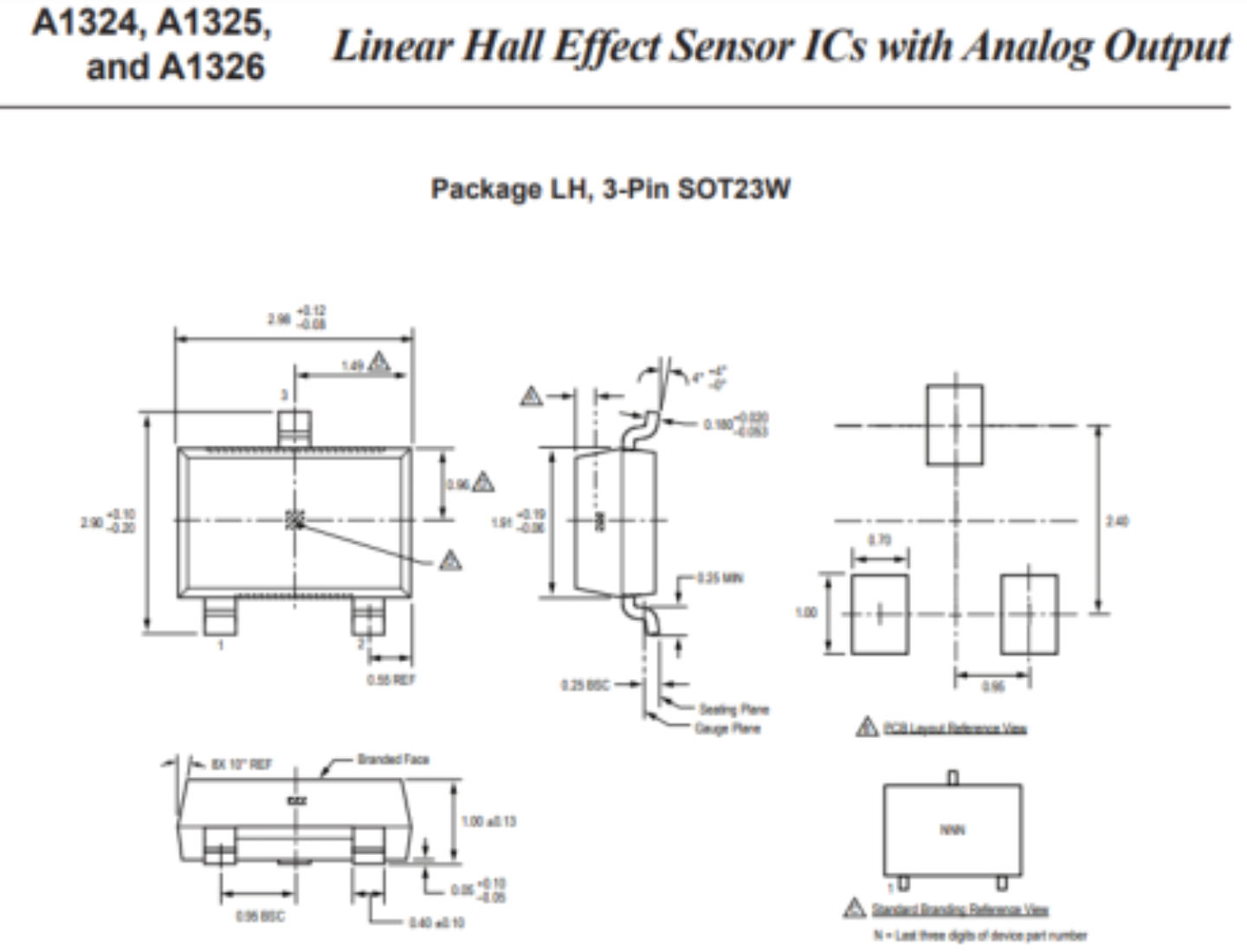
My Hall Sensor Board 2
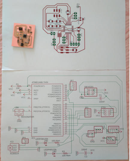
As I have learned in past weeks, to create my electronic board, I have used the “ Eagle ” software to prepare the schematic (fig.1) and the electrical connections named Board (fig.2). For this board I decided to have more pins available for further development, for example to use it in my final project. I think it is useful to multiply the power and ground pins in more contacts and also have extra pins available.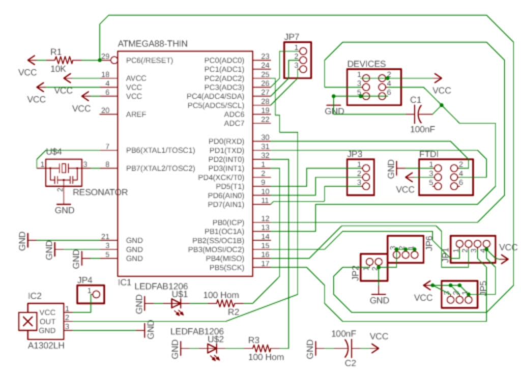
1 Eagle Schematic
2 Eagle Board
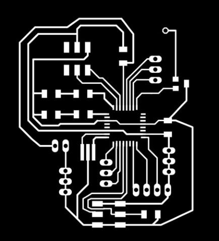
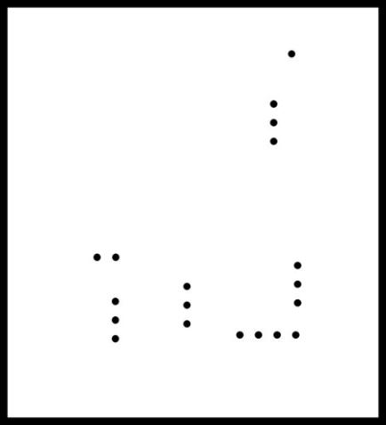
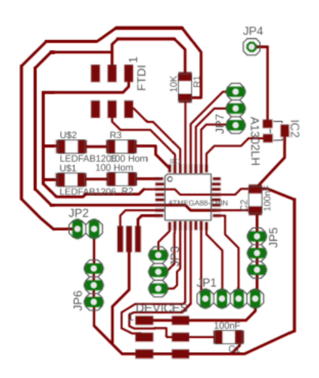
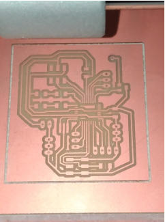
fig.3 “Traces”
fig.4 Outline and holes
Program the Board
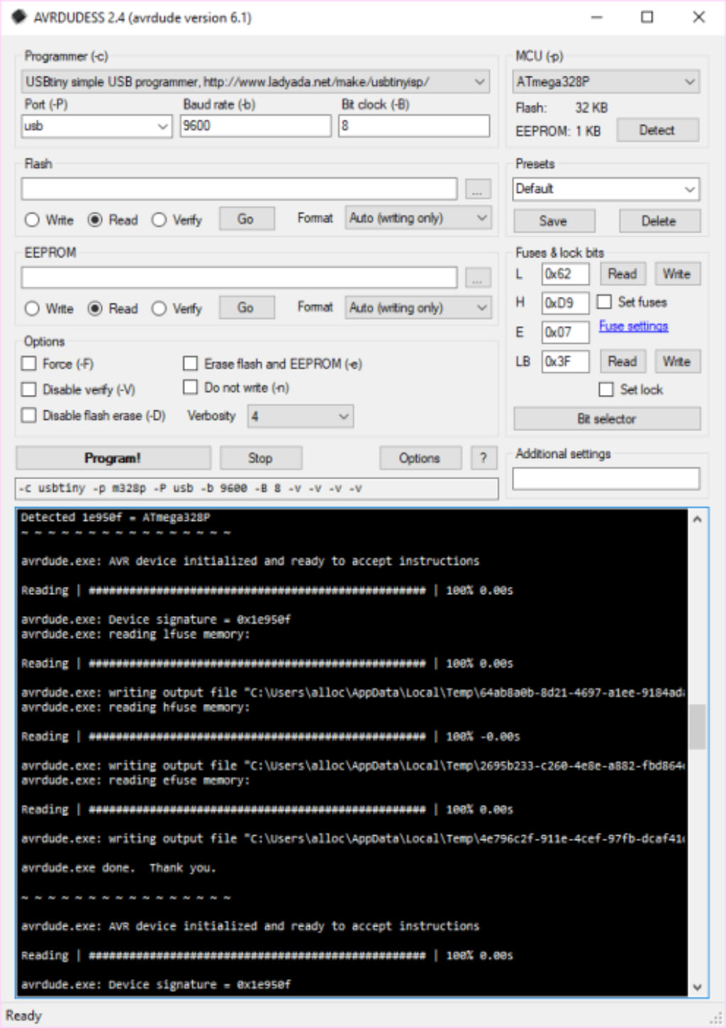
To program my electronic card I have used the “Arduino ide”. Before proceeding with the programming I verified that the card hardware was fully functional. I used avrdude to establish the contact with the card and verified that it was working and ready to receive data. My USB-tiny programmer help me in this operation.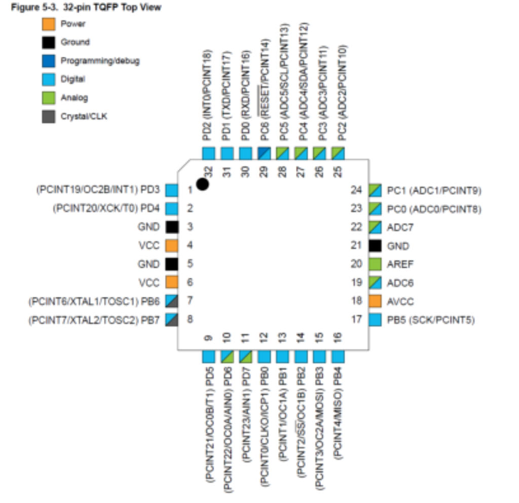
The Components
I chose ATMega328p TQFP card because it has many available pins. This choice comes from the fact that I would like that my card would be ready for possible other use and expansions, ( e.g adding other sensors, servo motors ecc)
Partlist exported from C:/Users/UTENTE/Documents/eagle/HALL SENSOR 2/HALL SENSOR 2.sch
Qty
Value
Device
Package
Parts
Description
1
PINHD-1X1
1X01
JP4
PIN HEADER
1
PINHD-1X2
1X02
JP2
PIN HEADER
4
PINHD-1X3
1X03
JP3, JP5, JP6, JP7
PIN HEADER
1
PINHD-1X4
1X04
JP1
PIN HEADER
2
PINHD-2X3-SMD
2X03SMD
DEVICES, FTDI
PIN HEADER
2
100 Hom
RES-US1206FAB
R1206FAB
R2, R3
Resistor (US Symbol)
2
100nF
CAP-US1206FAB
C1206FAB
C1, C2
1
10K
RES-US1206FAB
R1206FAB
R1
Resistor (US Symbol)
1
A1302LH
A1302LH
SOT23-W
IC2
Linear Hall Effect Sensor ICs
1
ATMEGA88-THIN
ATMEGA88-THIN
TQFP32-08THIN
IC1
2
LEDFAB1206
LEDFAB1206
LED1206FAB
U$1, U$2
LED
1
RESONATOR
RESONATOR
EFOBM
U$4


Control of readiness of the Device
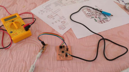
Having connected the electronic board to the “Usbtinyisp” programmer (built in the first weeks of the fablabcourse) the “Avrdudess program” confirms that everything is ready for programming. At this point, I start the “Arduino ide” and start typing the code of my software. When the code is written, I connect the hall sensor board to the “usb to ttl serial converter”. Doing so, I can test the data coming from the magnetic sensor.Baud rate? unexplained mystery…
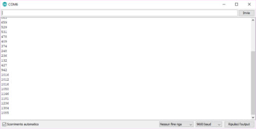
At this stage I encountered a very unusual problem .... I studied that in the serial protocol the transmission and reception’s speed should be the same. The speed is measured in baud rate. Usually, the default value is 9600 with bit 8 no parity, bit stop 1.. Unexpectedly, when I connected my card programmed with a baud rate 9600, the arduino serial monitor did not receive any data! All was set to 9600, even the usb to ttl serial converter.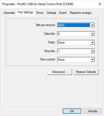

however
it
did
not
work
...
the
serial
port
was
transmitting
but
the
computer
did
not
receive
the
data.
Then
I
installed
a
serial
port
monitoring
software
to
figure
out
where the problem was...

Unbelievable ...
I then tried to change some parameters. Changing the reception speed, I saw strange symbols appearing on the screen .... and tan error related to the frame uart ... I then understood that something was misaligned and I kept changing the values. Atbaud rate 600, everithing started to work again. Possibly the default value of 9600 was divided by 16 ... 9600/16 = 600. Taking into consideration this, I modified the transmission value accoridngly: 9600 * 16 = 153.600 and found the solution to all the problems !!! Everything was working well eceiving on the serial 9600 ... but I could not understand the reason for this problem, maybe it could be something related to the microcontroller. I haven’t understood yet.
Final Conclusions
Reprocessing the card was a good job, and despite the problem of the baud rate my magnetic sensor works very well. Obviously I tried the card on different computers and everything is fine.Upgrade! 01/05/2018
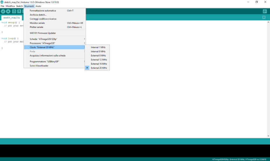
finally I solved the problem, I realized that the error was in the processor clock settings. By searching the web, I found a library for arduino that allows you to set the external clock to 20 MHZ. I have downloaded the library, reconfigured the fuses , and the card now works at 9600 regularly. Problem solved!
Supported Chips and Clocks
ATmega8/168: The chips used in early arduino boards (e.g. Arduino NG, Arduino Diecimila).
ATmega328p: The chips used in recent arduino boards (eg. Arduino Duemilanove, Arduino UNO).
ATmega168p/328: Different but functionally equivalent to the above. People sometimes buy these by mistake.
The
core
delay()
function
is
not
very
precise
for
clock
rates
other
than
external
8
and
16MHz.
The
internal
clock
should
provide
enough
precision
for
most
cases but external 12 and 20 MHz are useful only if your code does not depend on precision timing.
Install
Open the Arduino IDE preferences window and add the following URL to the Additional Boards Manager URLs list:
https://raw.githubusercontent.com/carlosefr/atmega/master/package_carlosefr_atmega_index.json
Now
go
to
Tools
>
Board
>
Boards
Manager
and
search
for
Barebones
ATmega
Chips.
Select
it
from
the
list
and
click
Install.
A
new
section
called
ATmega
Microcontrollers will immediately appear in the Tools > Board menu.
My Final Test
In this video you can see the complete test of my card. The sensor’s data are read by my software and graphically represented on the screen as red ellipses that are synchronized with a sound in relation to the value provided . See More details on the output device page.
Next
step
is:
to
export
the
images
in
order
to
be
able
to
mill
the
copper
board
with
the
“Roland”
milling
machine,
export
the
files
in
.png
format
and
prepare
them
for
processing
with
the
fab
moduls
online.The
files
are
traces
(fig.3)
and
outline
and
Holes
(fig.4).(
Gimp
Software
help
me
to
draw
the
holes and outline).
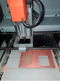
Milling machine in action!
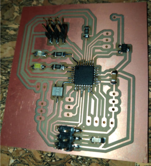

My Milled copper Board
I Start soldering!
I like to start to soldering with Avr microcontroller, in this case a ATmega 328p, so next all other components and at last the pin header.
Pinout of ATMega328p TQFP
My Board with AVR ATMega328p TQFP
My Board with all components
My Board and my Eagle project

Original Files and Useful Links
AVRDUDESS: the card is ready!
When AVRDUDESS is started, I first chose the correct programmer model from the list. My USBtiny is on the list. The next operation is Detecting MCU connected, I do this by clicking with the left mouse button on the "Detect" button. Immediately the name "ATMega328P" of MCU appeared on the field and I am very happy because my electronic card is alive!
/* HALL SENSOR BOARD V.2.0
code written by Giuseppe Allocca
FabLab class 2018
Santa Chiara FabLab SIena Italy
*/
//leds pins definition
int powerled = 3;
//white led
int comled = 2;
//blu led
int sensor= 16;
//Analogic pin
int sensor_value=0;
int pinsound=5;
//digital pin
void setup() {
// initialize serial:
Serial.begin(153600,SERIAL_8N1);
/* my usb to ttl serial converter divide serial baud declared by 16
and so...153600/16 =9600 I really don't know why!!! */
// initialize digital pin LED as an output and pin Button as input
pinMode(powerled, OUTPUT);
pinMode(comled, OUTPUT);
pinMode(sensor, INPUT);
pinMode(pinsound, OUTPUT);
// turn LED on:
digitalWrite(powerled, HIGH);
//Board power-on
digitalWrite(comled,LOW);
//comled off
}
// end void setup
void loop() {
/* activates serial transmission and blinking led blue
when sensor value if different then normal status */
// read the sensor value from pin 16
sensor_value=analogRead(sensor);
// "or" operator to control low or high value change depending by polarity of magnet
if ((sensor_value)>511||(sensor_value)<508)
//blue led blinking synchronized to sensor_value
{digitalWrite(comled,HIGH);delay(map((sensor_value),20,1023,1,10));digitalWrite(comled,LOW);delay(map((sensor_value),20,1023,1,10));
//remap value of sensor to 1-100 scale and send the value to serial port
Serial.println(map((sensor_value),13,450,10,900));
//sound zone
digitalWrite(pinsound,HIGH);delay(map((sensor_value),20,1023,1,10));
//start beep
digitalWrite(pinsound,LOW);
//end beep
// the sound are synchronized to sensor_value than blue led
}
// end if
}
//end void loop
My Arduino code with Serial speed problem…
Useful PinOut of ATMEGA328p with Arduino pin number
Arduino plotter monitor function
Arduino serial monitor function