Week 9: Embedded Programming
Group project:
Experiment with other architectures
Individual project:
Read a microcontroller data sheet.
Program your board to do something, with as many different programming languages
and programming environments as possible
ATtiny44 datasheet
Datasheet. Read it. Other than getting pin configurations and falling asleep several times, this is useful when I need information on specific subjects and functions on the microcontroller. Reading it pre-emptivily when you have no relevance point is almost useless, but browsing through gets you the idea what it can do. Here, ATtiny44A is a CMOS 8-bit microcontroller, based on the AVR enhanced RISC architecture, featuring(amongst others):
- 120 instructions and 32 general purpose working registers, approaching 1 MIPS (Millions of instructions per second) per MHz.
- 4KB of in-system, self programmable flash memory for program storage, 256 Bytes of in-system programmable EEPROM data storage and 256 Bytes of internal SRAM data memory
- 12 general purpose input/output lines, where 8 pins are for port A(ADC/timer/counter/SPI/interrups) and 4 pins are for port B(Reset on PB3). See pin descriptions and alternate port funtions to see what can be done and where
- Internal/external interrupts, all with interrupt vectors and priority based on it's address
- Calibrated internal or external oscillator(check out clock subsystems and clock sources)
- One 8-bit and One 16-bit Timer/Counter, for accurate program execution timing (event management),
wave generation, and signal timing measurement
- 10-bit analog/digital converter with 8 single-ended input pins or 12 differential pairs of input pins with programmable gain stage(1x/20x)
These are some of the things you can come back to, when the appropriate need arrives. In addition, there are few other things one might want to know:
- High endurance, 10k erase/write cycles for flash, 100k for EEPROM
- Operating voltage of 1.8V - 5.5V.
- Temperature range -40°C to +85°C
- Low power consumption with 3 selectable power saving modes
- Packaging(dimensions and layout)
Later on, I found datasheet to be usefull on week 12 and 13, and on my final project.
Atmel studio
Downloaded and installed Atmel Studio 7.0. Pretty straightforward, just had to click next several times to install all dependancies.
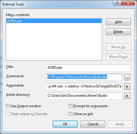
From tools -> external tools, add avrdude. I had installed it previously so I only needed to set it up. Located the software and added command, arguments and initial directory:
Also remove tap from Close on exit to see what happens when building/compiling.
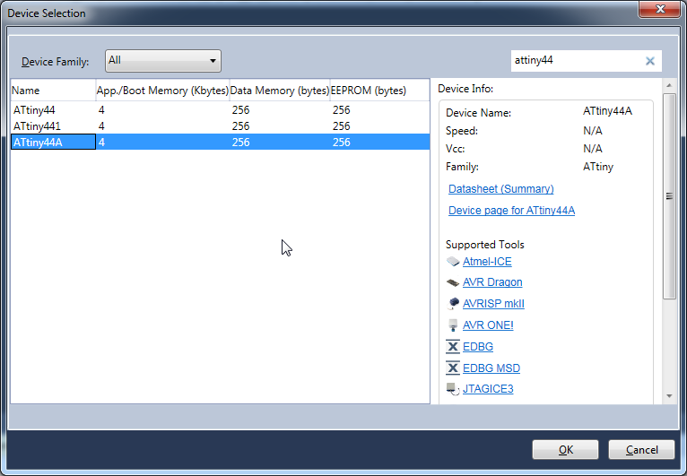
When I had environment set up, I started a new project. Typed attiny44 to the search field and selected ATtiny44A from the list.
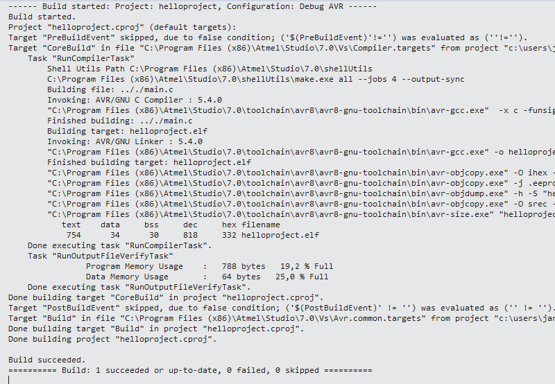
I had previously used Neil's helloworld code from command line to program my hello world board. Now I wanted to do it again from Atmel Studio. So, I copied Neil's code, and added 20 MHz line:
Hitting Build now builds and compiles the project.
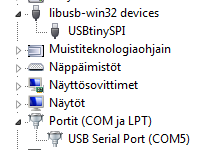
If not previously, now is the time to check everything is ready before hitting that avrdude button. Connect programmer and hello world board and check from device manager and see that USBtinySPI is recognized and I have USB serial port(COM5).

So, when everything was okay, I clicked previously created avrdude under Tools menu.
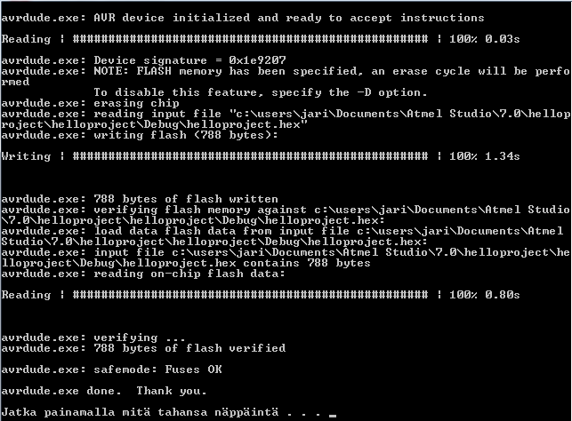
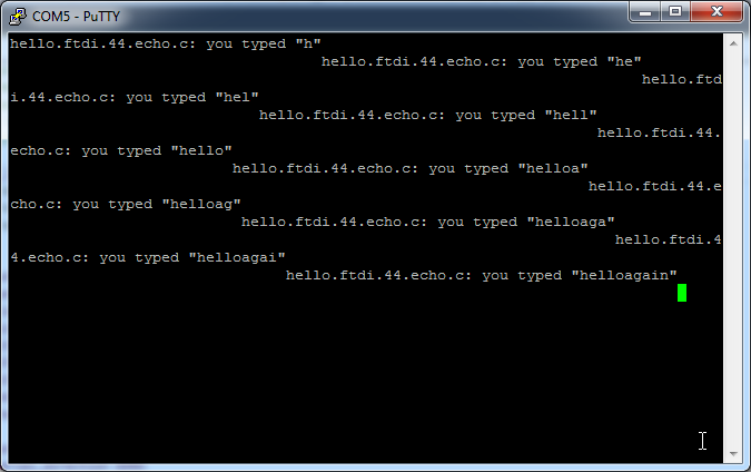
Tested connection with putty at com5 and 115200 baud rate, works nicely.
Next I downloaded button and led code blink_button.c from Ivan's page. Basically I just wanted to see what's going on in there. Builded and then run avrdude and it worked flawlessly. Didn't like how the led was on only when the button was pressed, so modified the code to make it work like a switch.
uint8_t button_lock = 1; // Button press/release lock. This is to disable serialized button activation.
while (1)
{
//Check if button is pressed (its value is 0 because the button has a PULL-UP resistor)
uint8_t val = PINA & (1 << PA7);
// Switch button mechanic
if(!val){
if (status && button_lock) {
PORTB = PORTB & ~(1<
}
else if (!status && button_lock) {
PORTB = PORTB | (1<
}
button_lock = 0; // Button press - locked
}
else {
button_lock = 1; // Button release - unlocked
}
}
After build and running avrdude, it worked perfectly. Full code can be found at the bottom of this page.
Arduino IDE
Wanted to try different setup as well, so downloaded Arduino IDE installer for windows and installed it with defaults.
Guide for setting up the environment for ATtiny and Installing ATtiny support in Arduino 1.6.4. From preferences, click Additional Boards Manager URLs and paste following address:
Then from tools, select Board -> Boards manager. Scroll to bottom and select attiny, and install it.
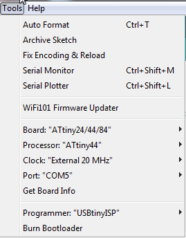
Now you can select the right board,processor and the rest as following:
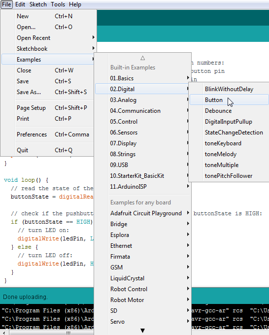
Making button to do something, so grabbed an example.
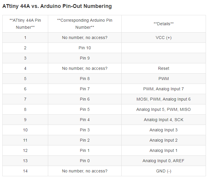
For getting right pins to get attiny to work in arduino, I took a look at data sheet. I knew that I've been using pin 5 which was PB2(LED) and pin 6 which was PA7(Button), and those worked.
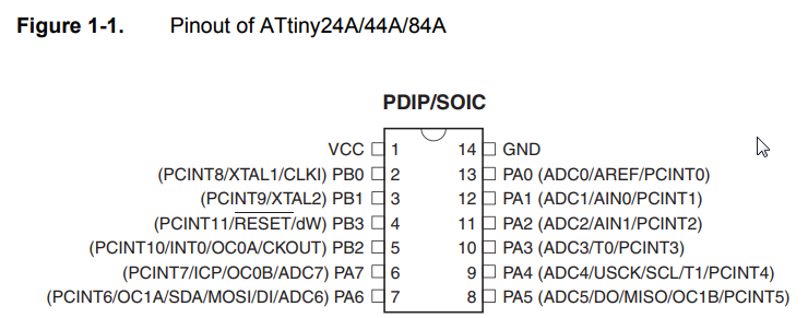
And when comparing to arduino(see ATtiny vs Arduino picture below), pin 8 is LED, and pin 7 is Button.
Modified the example button code:
const int ledPin = 8; // the number of the LED pin
And changed HIGH to LOW and vice versa.
if (buttonState == HIGH) {
// turn LED on:
digitalWrite(ledPin, HIGH); // this was low
} else {
// turn LED off:
digitalWrite(ledPin, LOW); // this was high
}
From sketch, verify/compile and then upload using programmer.
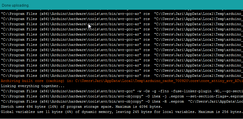
Everything worked nicely. Now I copied my switch button code and made changes to match arduino. Upload again, and it works as it should!
Group project
Group efforts can be found here.
Files
Switch button code: switchbutton.c
Modified button example: Arduino_attiny_button.ino
Switch button code for Arduino IDE: Arduino_attiny_switch.ino

