Week 4: Computer-controlled cutting
Group assignment:
Characterize your lasercutter, making test part(s) that vary cutting settings and dimensions.
Individual assignment:
Cut something on the vinyl cutter.
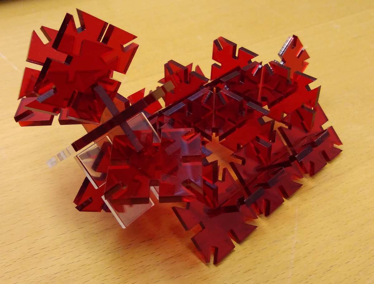
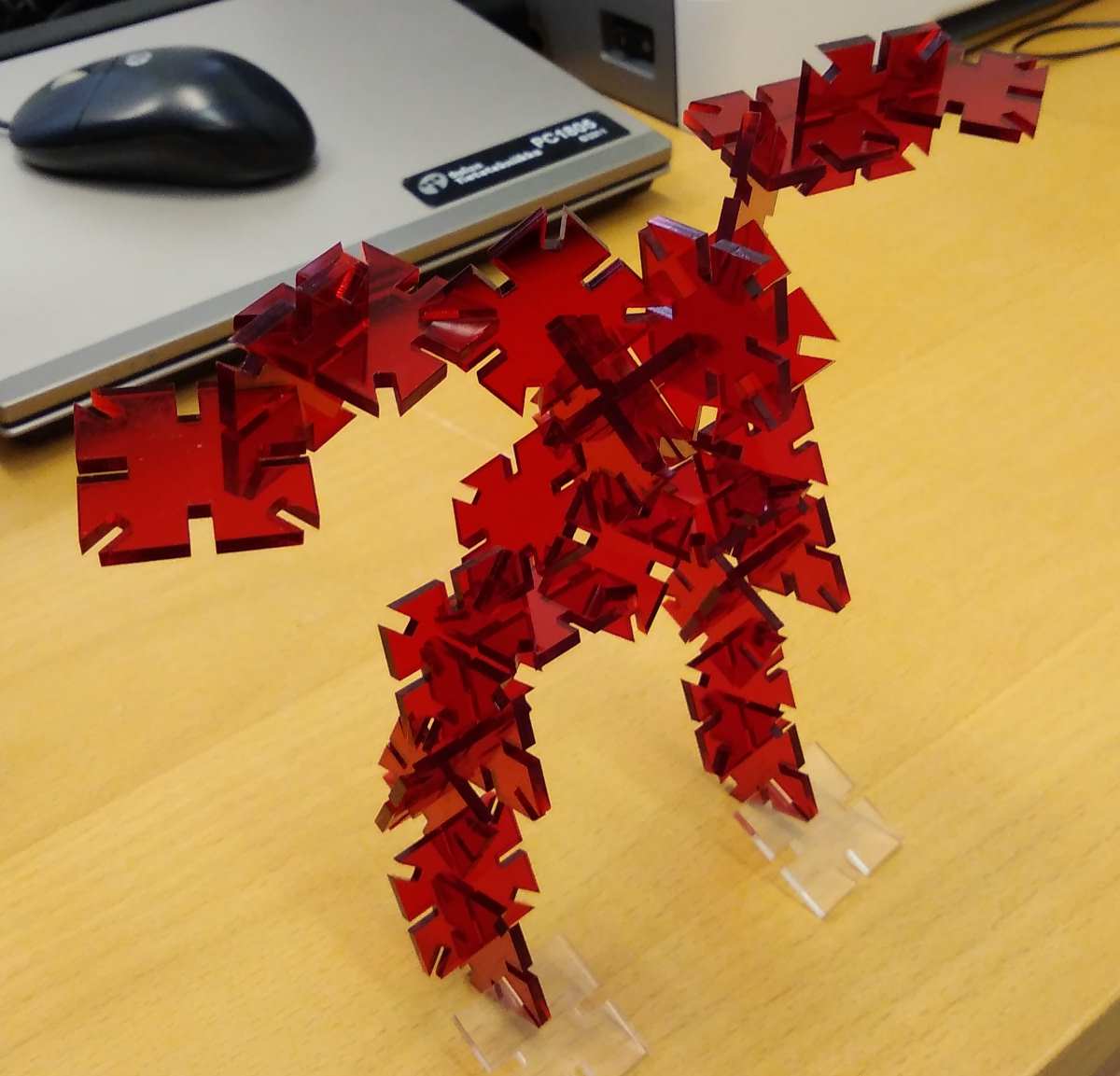
Design, lasercut, and document a parametric press-fit construction kit, which can be assembled in multiple ways, accounting for the lasercutter kerf.
Vinyl Cutter
Started up by making a simple design with Inkscape. It's a text that goes to mail box stating NO FREE MAIL. Used text tool and placed it to the bottom left corner to minimize material loss.

Next had to setup out Vinyl cutter, Roland CAMM-1 GS-24. Found a piece of vinyl, and moved the border markers to the edges. Attached the piece by pulling the lever in the upper left side of the machine.
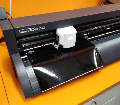
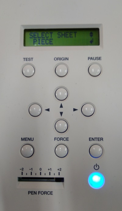
From VC's menu, choose Piece from Roll/Piece/Edge(if you got piece like I did).
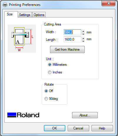
Machine then initialized itself and was ready to print. Hitting print, choosing Roland GS-24 as a printer, then from printing preferences click 'Get from machine' to get the width of the piece(set by border markers) and set the length you need.
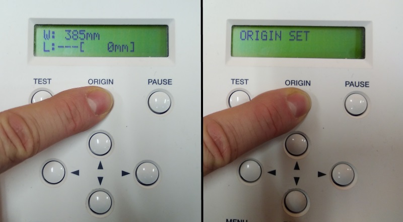
If I was gonna do another piece, I could manually move the cutter to the point of my chosing, and set origin there by holding the origin button until it start flashing.
After print was done, I had my piece of black vinyl.
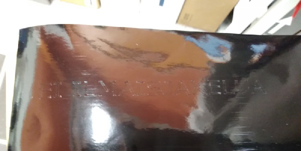
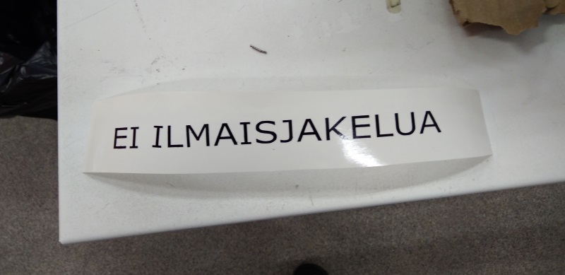
Then proceeded to apply the transfer sticker.
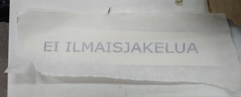
Removed the paper from vinyl sticker. Third letter got loose in the process, so had to manually put it back.

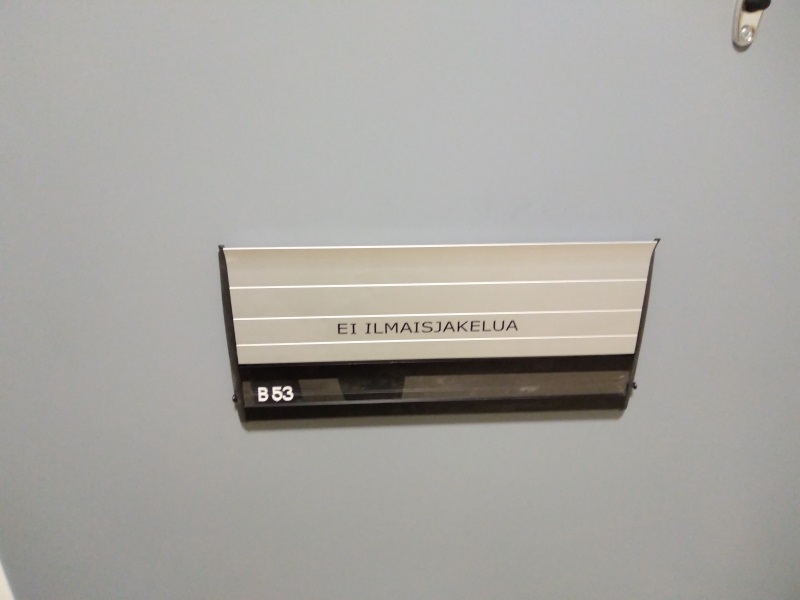
And when I got home, I sticked it to my front door.
Laser Cutter
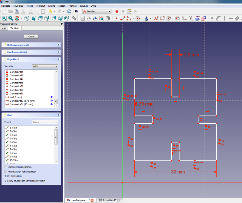
To start designing my press fit contruction kit, I went with freecad. It feels easy and intuitive, and there is nice guides if you need something. Quickly drew a box, added more boxes, cutted out lines I didnt need. Added equality constraints and measures for gap width, depth and side length.
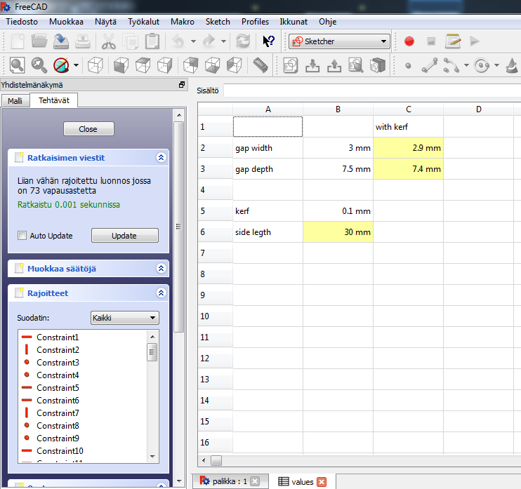
Created spreadsheet so I can do it by the numbers. Yellow cell means I created an alias for that cell, so I can easily get the value in sketcher.
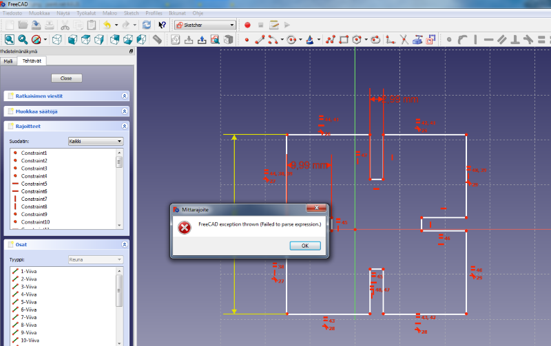
Initially everything was fine, but when I started experimenting with the values, I got an error. Change the value in spreadsheet, apply it again in sketcher and it worked.
I made my design a bit more complex. Added more constraints, to make every hole equally deep, corners equal etc.
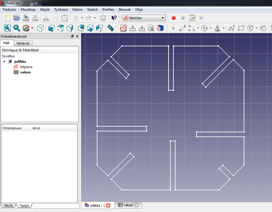
And the it exploded in my face. I tried removing some constraints and pull it back, but the whole structure was demolished and line endings didnt connect anywhere.
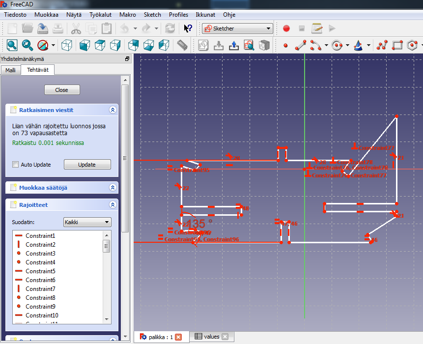
I decided that it was probably faster to build it again from scratch, but because of the errors and chance of this happening again, I chose to switch to Fusion 360.
Starting with Fusion wasnt that different. Make sketch, create a box, few more boxes, trim it down. Very quickly I was in the same point when initially using freecad.
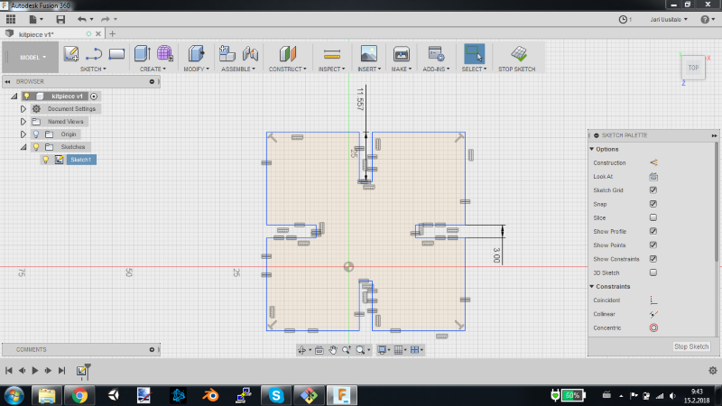
Using parameters was a little bit easier in Fusion. Less clicking, at least. Created few user parameters, from Modify > Change Parameteres and under User parameters click plus sign to give name and value. Then applied them to the sketch by clicking value in design and giving it the created parameter name.
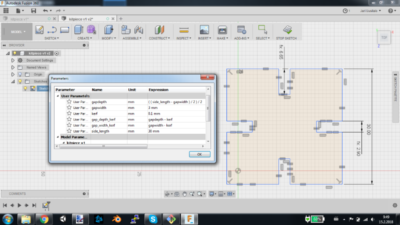
At this point, I made an test cut with the laser cutter. To do that, I exported the sketch as a DXF-file to Inkscape. There I applied line width of 0.02mm for cutting, saved it as a PDF-file and went for the laser cutter.
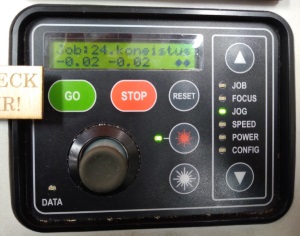
From machine's own LCD menu, chose focus. Applied the focus piece and moved the platform so that the focus piece gently touched the surface. Accepted the change by pressing the control stick, and removed the focus piece.
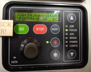
Changed the origin of laser with jog. Moved it to right position, indicated by the red dot on material surface. Accepted that and the machine was ready.
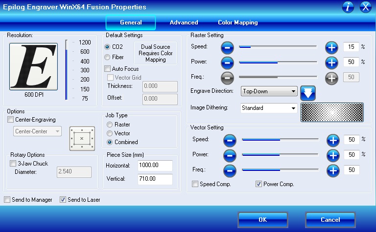
From computers print menu I checked that the machine was right, and then clicked properties.
In General laser cutter had 2 areas: vector and raster. Vector settings are for cutting the piece, while raster is for texturing.
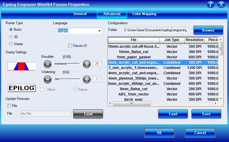
Opened up advanced, which had some material presets ready. Chose 3mm acrylic combined, and from General settings just changed combined to vector. Vector setting for acrylic were 8% speed, 100% power and 100 frequency.
Hitted print, went back to the machine saw that my file in the Job-menu. Checked that air ventilation was ok, among everything else, I hit go.
Cutted two nice test pieces.
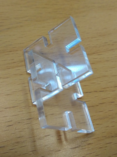
Next I made my design a bit more complex by adding holes to the corners. With angle and equality contraints place, I added circular pattern of 4 to make it every corner.
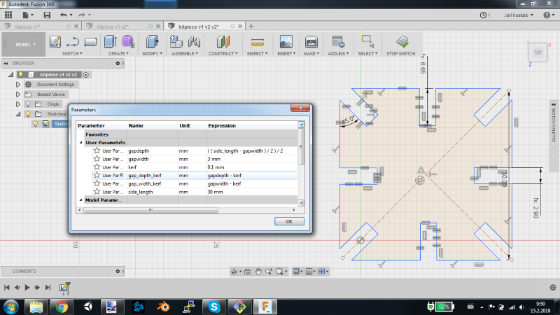
When I was satisfied with the design, once again imported the DXF-file Inkscape. This time, however, was a bit different.
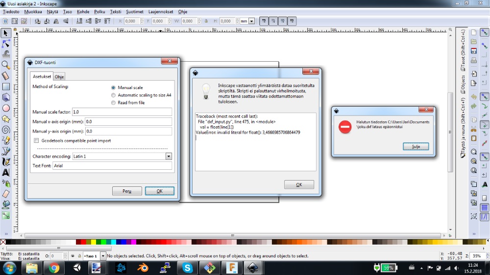
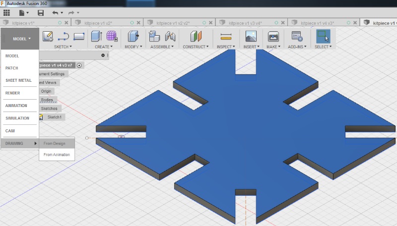
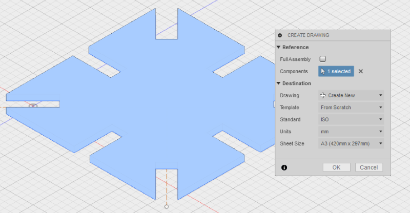
When consulting with our instructors, they said I should try with drawing and output as PDF. So I extruded my design to give it a look, then selected drawing from design.
Thought I didnt need whole thing, just the surface, so crossed off Full Assembly..
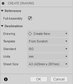
Then selected the surface I wanted and clicked ok.
In drawing I changed orientation to TOP, Chose only visible edges and scale to 1:1.
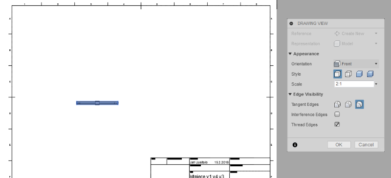
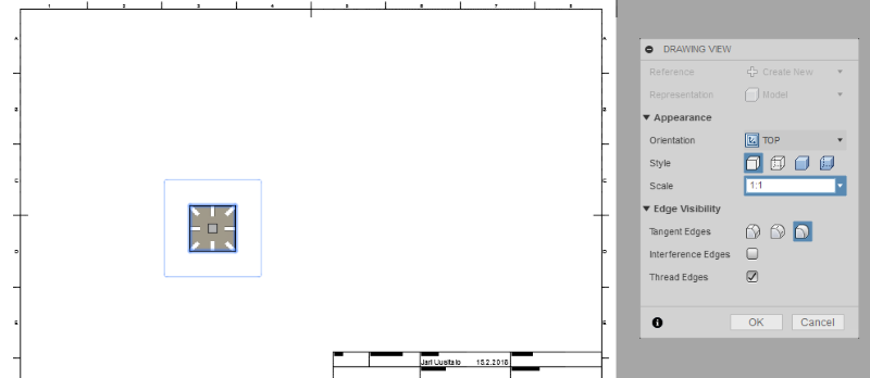
Then removed everything else in the drawing and choose output as a PDF. Though it had this lineweights box which I didnt know, so I saved it in both.
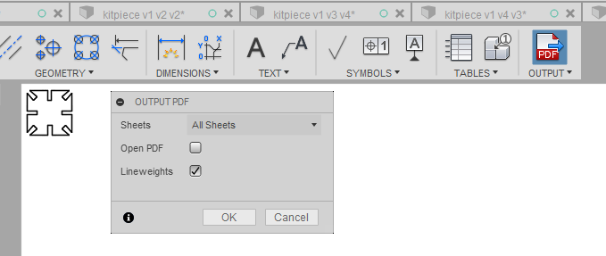
Opened the PDF-file in Inkscape to check lineweigths. In Objects menu however, I saw four paths, which meant that the outline was drawn four times. Swapping back to fusion, I saw 4 bodies in the browser, so it seems I made the drawing from all of those. Deleted the other three in Fusion and in Inkscape , changed lineweight to 0.02mm and it was good to go.
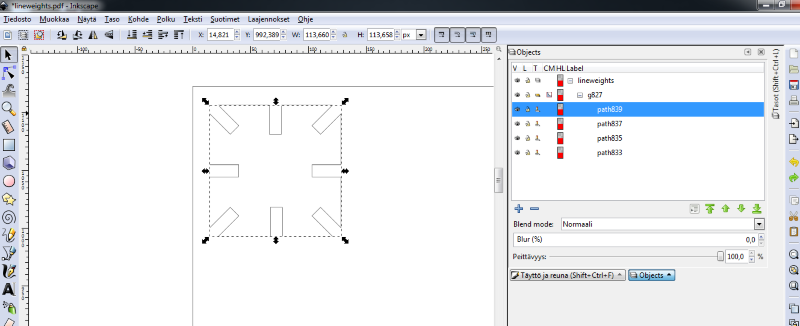
Opened the no lineweights version and this one had the same problem, but it was all single lines and not continuous. In the end, results wuold be exactly the same, but removing extras in this one might provide more work, so proceeded with the first one.
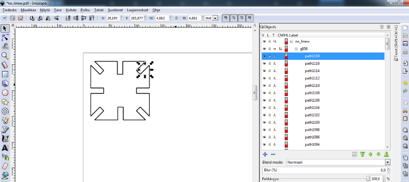
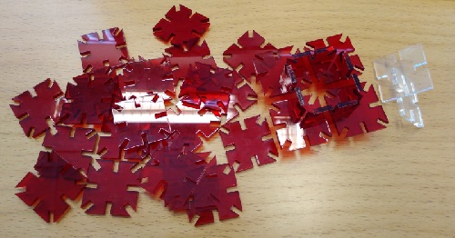
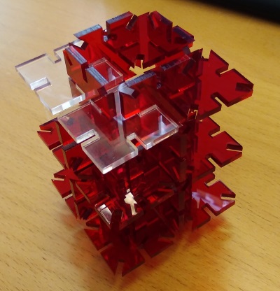
Went through printing(cutting) again, with same settings(3mm acrylic) as before and finally got my pieces cutted out.
Group assignment
For group work, I created testing piece in freecad, made it parametric so it would be easy to change kerf. This was imported to Inkscape multiple times, with different kerfs.
We took turns on cutting, so every one would be familiar with the process when doing their own project.
We tested the kerf on the bigger one of our lab's laser cutters.
Pieces were cut on the 3mm acrylic and 3mm MDF.
For pretty pictures and group site go here.
Files
Vinyl Cutter Inkscape designFreeCad try
Fusion 360 Test piece
Fusion 360 Press fit kit piece
No lineweights test PDF
Lineweights test PDF

