Week 10: Molding and Casting
Group project:
Review the safety data sheets for each of your molding and casting materials,
then make and compare tests with each of them
Individual project:
Design a 3D mold around the stock and tooling that you'll be using,
machine it, and use it to cast parts.
Design
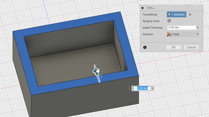
Software I used for this was Fusion 360, since I've become somewhat familiar with it. I created a 27mm x 36mm x 15mm box(create > box) and added shell modifier(modify > shell) and selecting top face of the box and giving it the wall thickness value of 3mm.
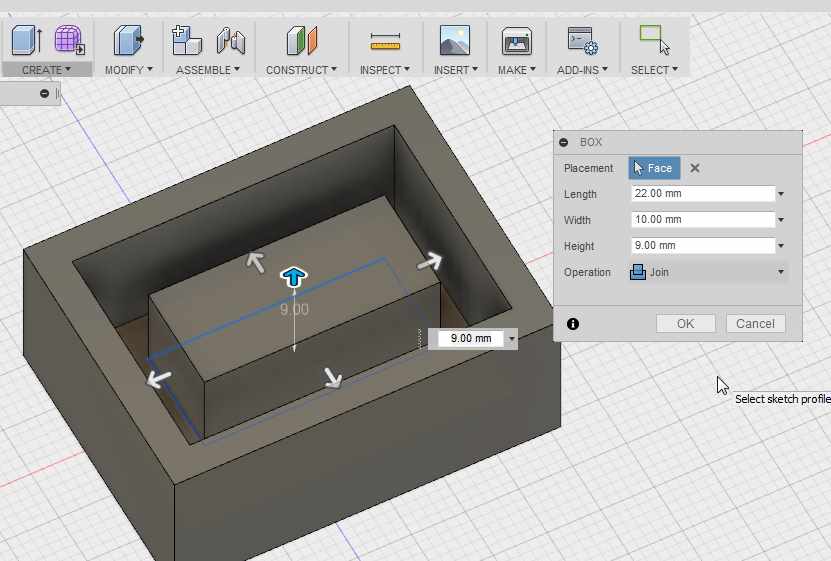
Then I created another, smaller box inside the first one. From the dimensions menu I selected to join and streched the smaller box to the bigger one.
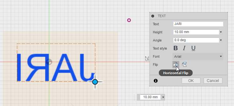
Selected smaller box top surface and right clicked on it, and selected create sketch. From sketch > text I created text object with my name, and flipped it around until it was looking like a mirror image.
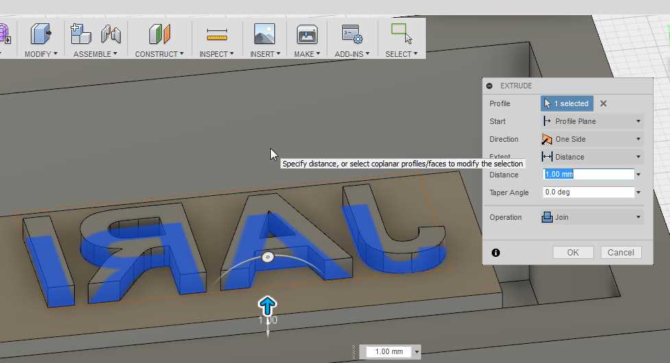
Clicked stop sketch to exit skecthing mode and then extruded the letters by 1 mm.
At this point I decided that I want outer line for my stamper, so sketched again smaller box top surface. Then added sketch > 2-point rectangle near the borders, making 1mm thick wall. Stop sketch, and then extruded the outer wall.
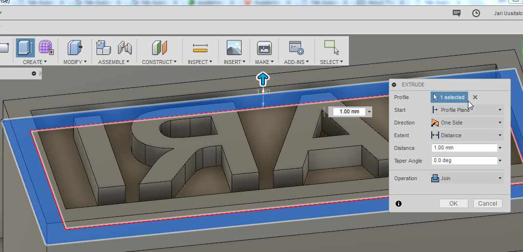
Final results.
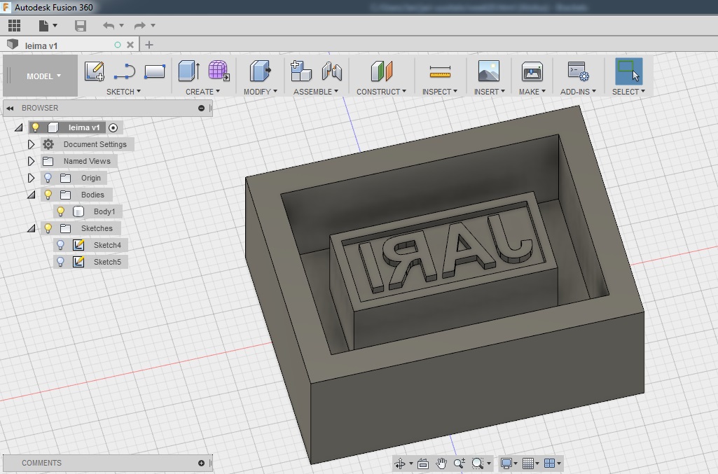
Toolpath
For actual toolpath I chose to use roland's own Modela 4. For roughing part, I chose 3.18mm flat milling bit and for finishing, 0.79mm flat milling bit. Material used was blue machinable wax.
Opened up my .stl file I made with Fusion, and started with set -> model. First set up the model so it is facing the right way, by selecting the top surface and/or rotating the model.
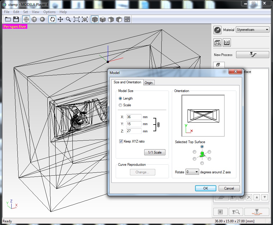
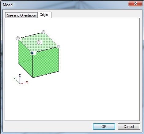
Change origin to match the milling machine origin point, which is the front left corner.
Switch view to rendering instead of wireframe to get more clear picture of whats going on.
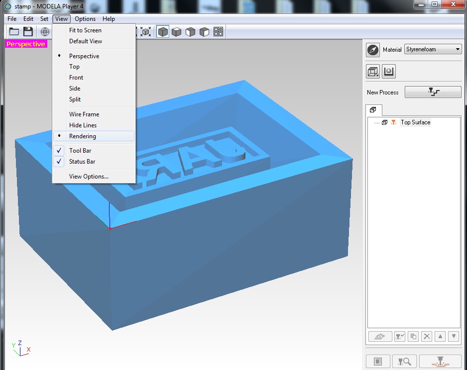
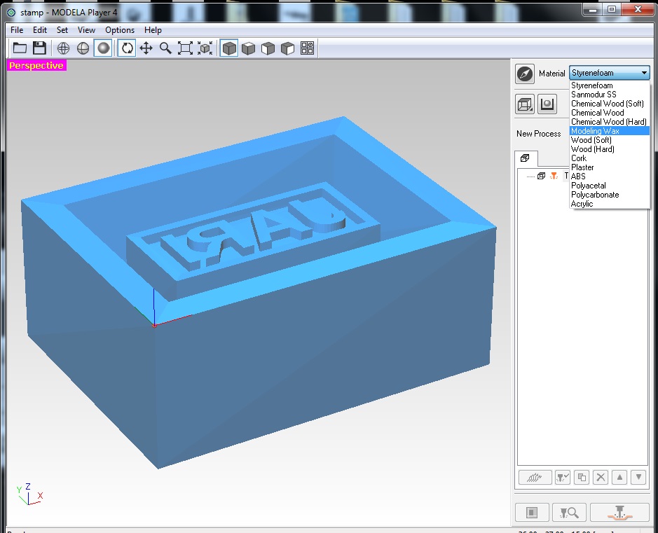
Change material to modeling wax
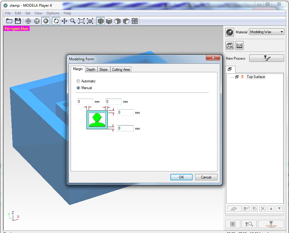
From modeling form remove margins
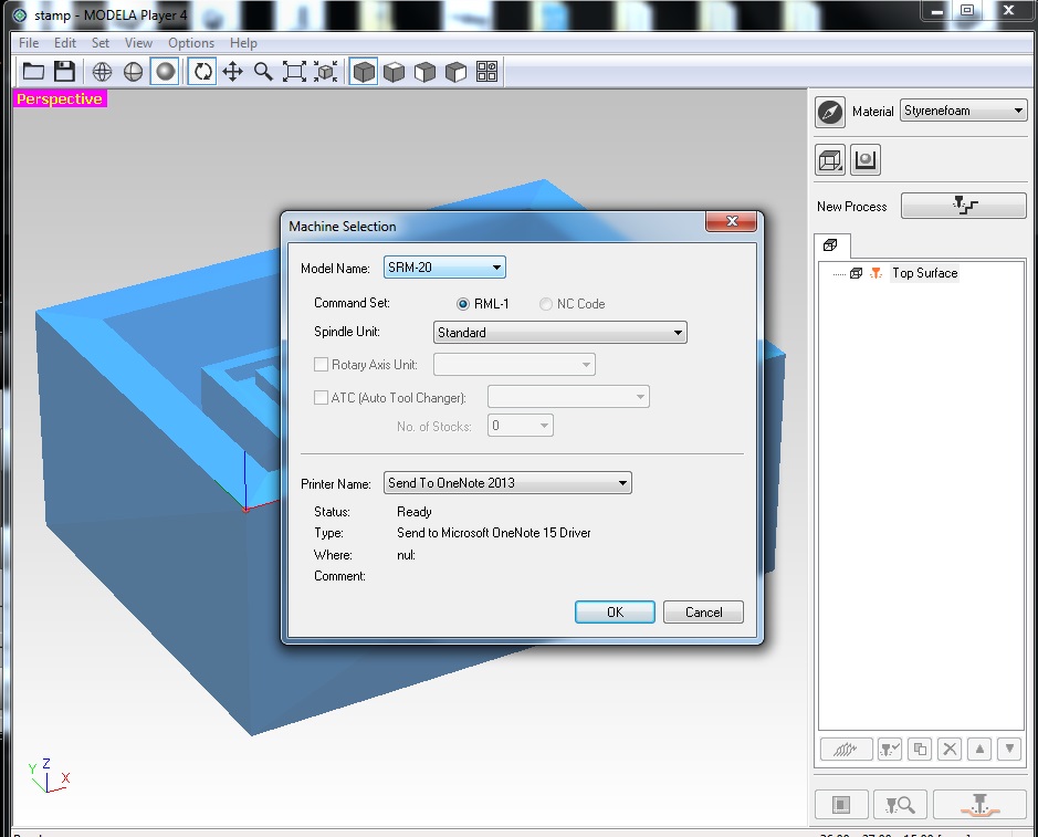
Change machine to correct one.
Create new tool for 3.18mm Flat. Add name and value. This is the roughing tool.
Register cutting parameters for roughing and finishing. I only changed roughing since I was gonna use different milling bit for finishing. In here XY speed is how hard it will push sideways. Since the material is machinable wax(ie. it's soft),XY speed of 30 mm/sec should do fine. Z speed is how fast we go up and down, but it is kinda non-factor(in this case), as we drill(mill) so little at a time. It is defaulted as 10mm/sec. Cutting-in amount is how much it will cut each passing, in this case cutting in is 1mm. Path interval will tell how much paths will overlap, so when using 3.18mm tool with 1.5mm Path interval, it's approximately 50% which is the recommended setting.
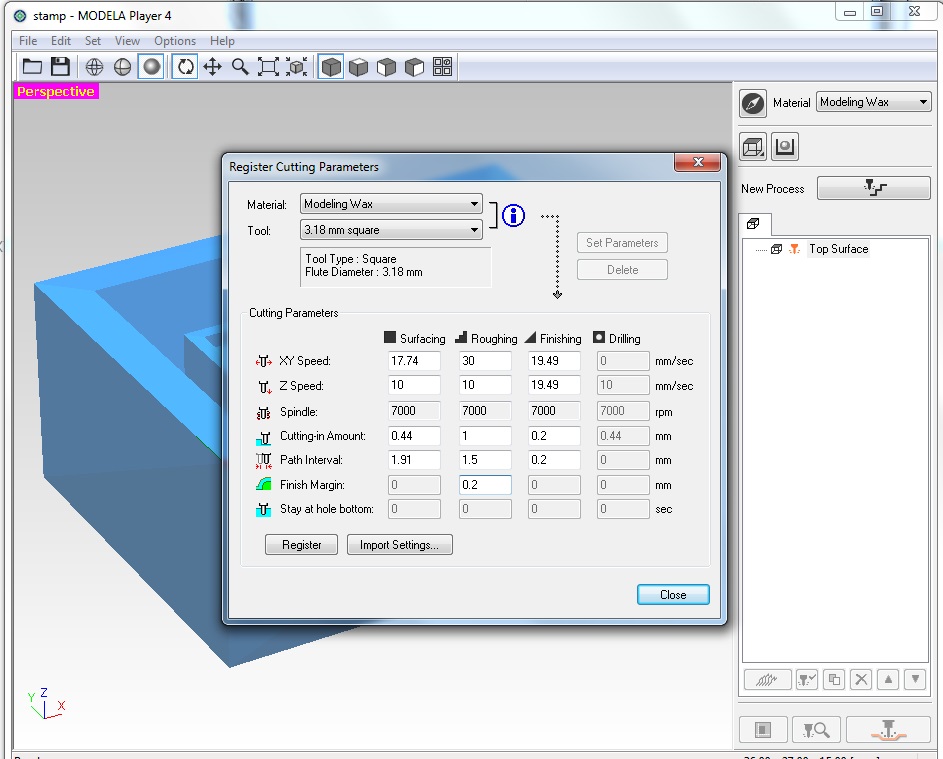
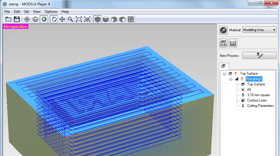
From new process, select roughing. Then go with defaults except change path type to Countour Lines and tool selection to 3.18mm flat. Accept, and tool path is generated.
Again new process, this time select finishing. Again, otherwise defaults, but path type change to scan lines(x+y). From tool, I selected 0.79mm flat and after that I restricted the cutting area by adjusting the area selecting rectangle in 'Cutting Area' tab, to only cover the letters in my design. I left cutting as defaults on this one(XY and Z speed 16mm/sec, path interval 0.2mm).
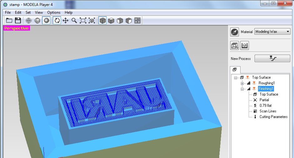
Checked simulations to see everything was displaying correctly. For some reason, simulator made almost 1mm corners in diagonal line in finishing toolpath, and couldn't get that to change. However, after milling it was fine.
Milling
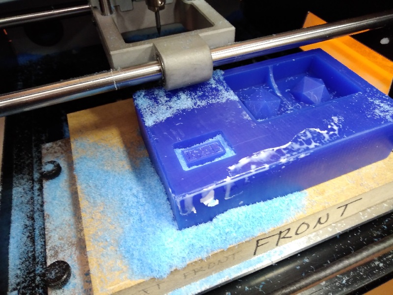
Attached the wax block to the milling platform with double sided tape. From SRM-20's control panel, set origin point to front left, and z-axis to the surface. Hit cut in modela. After roughing, machine paused and I changed the milling bit(and set z-axis again to surface for the new tool) and pressed continue. Estimated operating time, 20 minutes for roughing, 7 minutes for finishing.
Casting
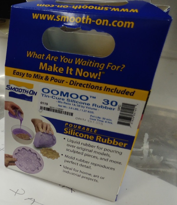
For casting the mold, I used OOMOO 30. Pot time 30 min, curing time 6 hours. Mixing ratio 1:1. Since I needed very small amount of the stuff, I did this with Marta. And to have some extra hands.
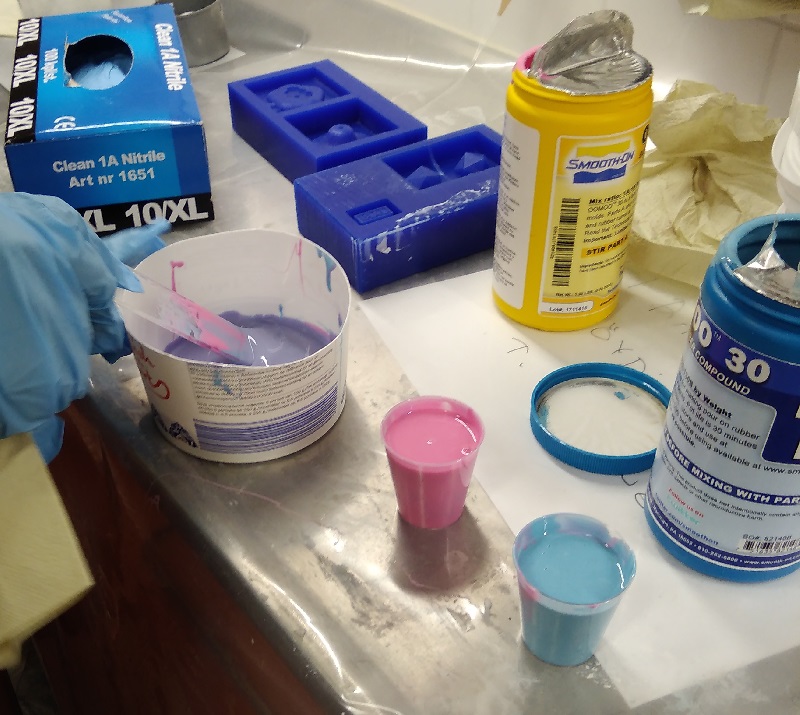
Started with equal sized small containers, and mixed them up.
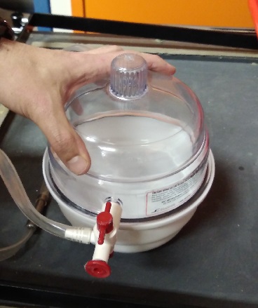
After approximately getting the right amount mixed up, it was put it the vacuum chamber to get rid of the bubbles for 20 minutes.
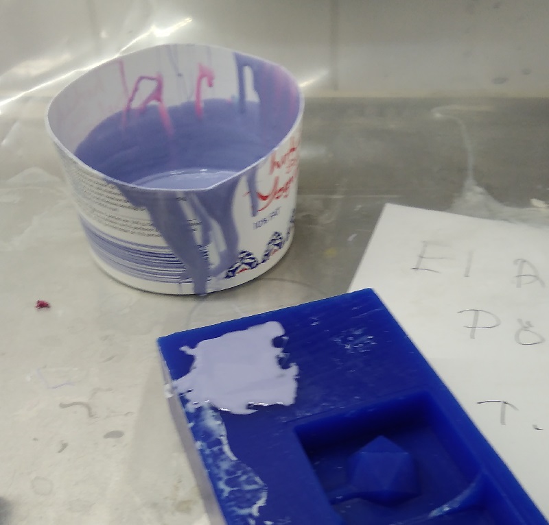
And finally poured it in slowly. Now it looks like a stain.
Got my silicon mold out.
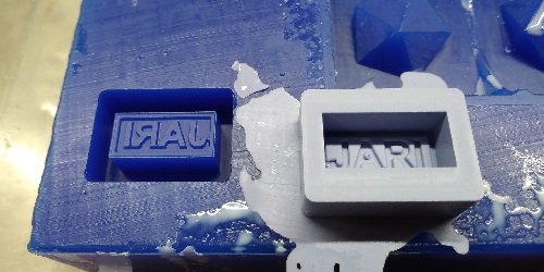
For casting the final product, I used liquid plastic Smooth cast 305.
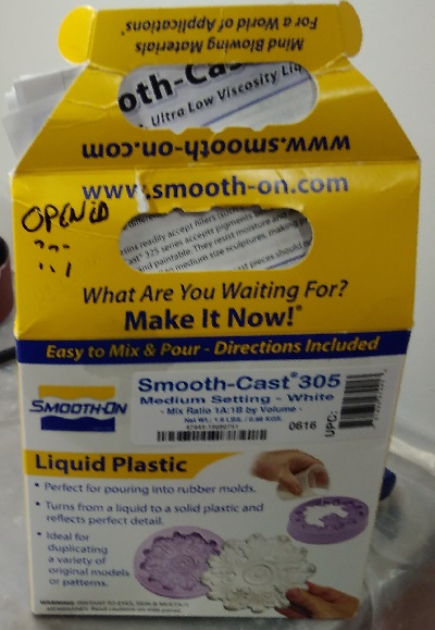
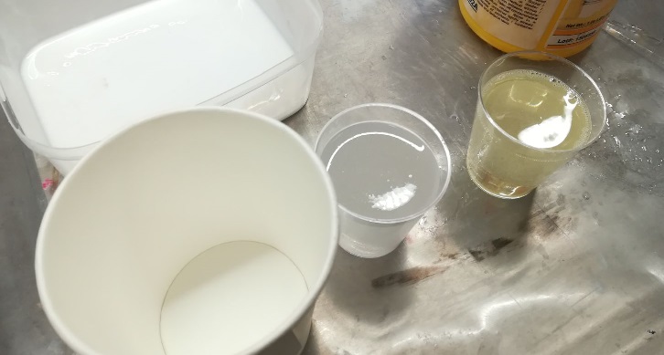
Mix them up and pour it in.
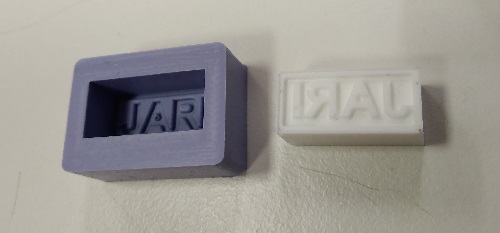
Final stamper.
Group project
Group efforts can be found here.
Final thougths/Problems
Mainly my process was straightforward, but there is one thing I should mention. When simulating finishing toolpath, simulator made almost 1mm corners in diagonal line(no picture, sorry), and couldn't get that to change. In the end, I just went with it to see if it really was gonna look like that. It didnt, and it worked just fine.
As I got this ready, someone pointed out that this is not 3D, but actually 2.5D. Real 3D would require design with slopes or curves; not straight vertical/horizontal line combinations. Instead of making it square, I could have made it rounded.
I was thinking about casting the propellers for my final project, but those would require alot more designing time and the thought came to me too late for this weeks time frame. And for that I would probably 3D print the mold of the mold, so the end results would be more consistent.
Files
Leimasin.f3dLeimasin.stl

