Week 11: Input Devices
This week's tasks:
- Group assignment:
- Measuring the analog levels and digital signals in an input device
- Link to the Group Assignment Page
- Individual assignment:
- Measuring something: adding a sensor to a microcontroller board that we have designed and reading it
Challenges:
- Soldering was more challenging this time. There were very little space for soldering the legs of ATtiny 45. So it might be a good idea to consider more space for very tiny componenets in the board design.
- Since I am not still good enough with Eagle, it was a bit difficult to fix the problem of overlapping nets.
- Debugging the issue with the board was quite challenging and demanded constant iterations of checking soldering, checking cable setting, checking schematic and other stuff.
- I used a soldering icon, which was had a thick tip. So unintentionally I spread solder in other parts of the board, which was not supposed to. So I had lots of challenges with cleaning them :-D
Considerations:
- Be careful with the orientation of the PHOTOTRANSISTOR.
- Do not be disappointed if your board does not look nice because of having an awful soldering time. It might still work by trying to identify some issues by careful and sharp eye examination especially asking the opinion of an expert regarding this ;-) Hopefully we have lots of helpful and knowledgable instructors in Fab Lab Oulu and they are always ready to guide us. And for this week thanks to Juha that guided us very well.
Technology used:
- Atmel Studio
- Eagle
- Milling Machine
- Soldering Iron
- Multimeter
- http://fabmodules.org/
My final project do not have any sensor. So to experiment this week's task I decided to try Neil's design for light sensor.
Designing the Board in Eagle
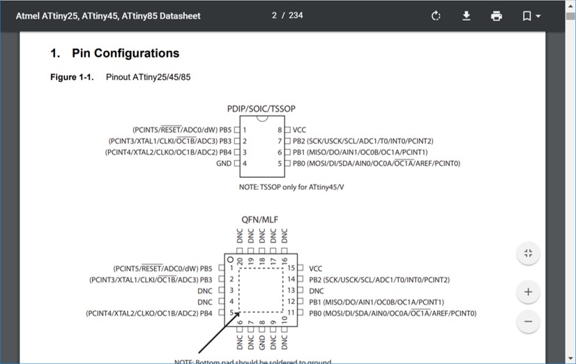
- Pin configuration for ATtiny 45 (ATtiny 45 DATASHEET)
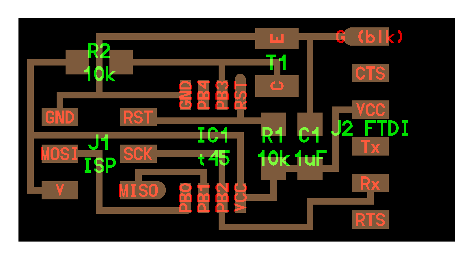
- Neil's Borad
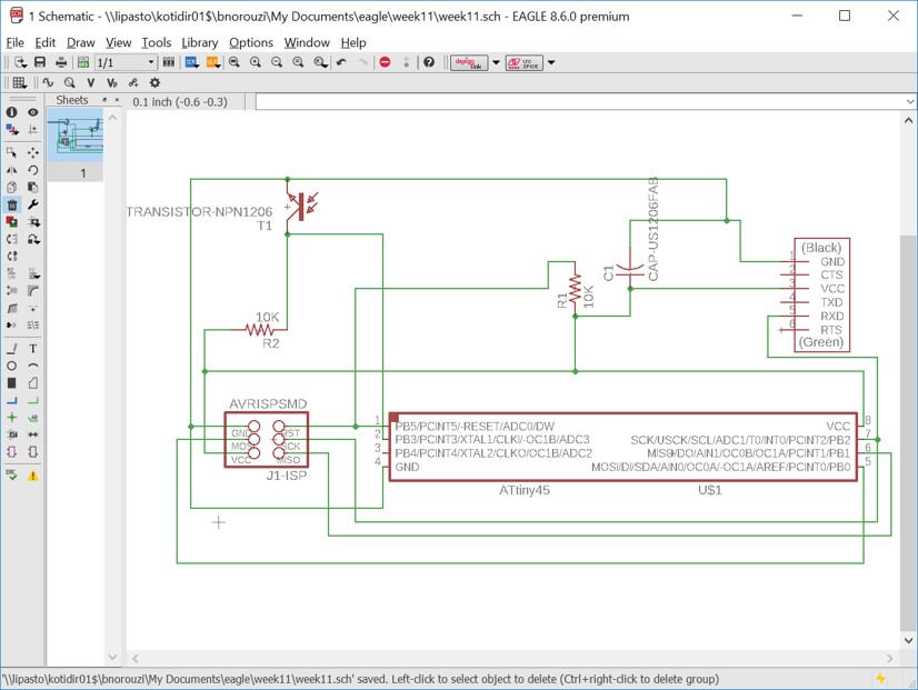
- The Schematic:
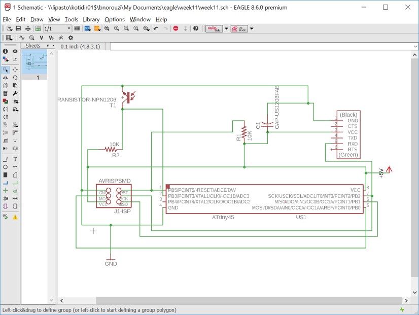
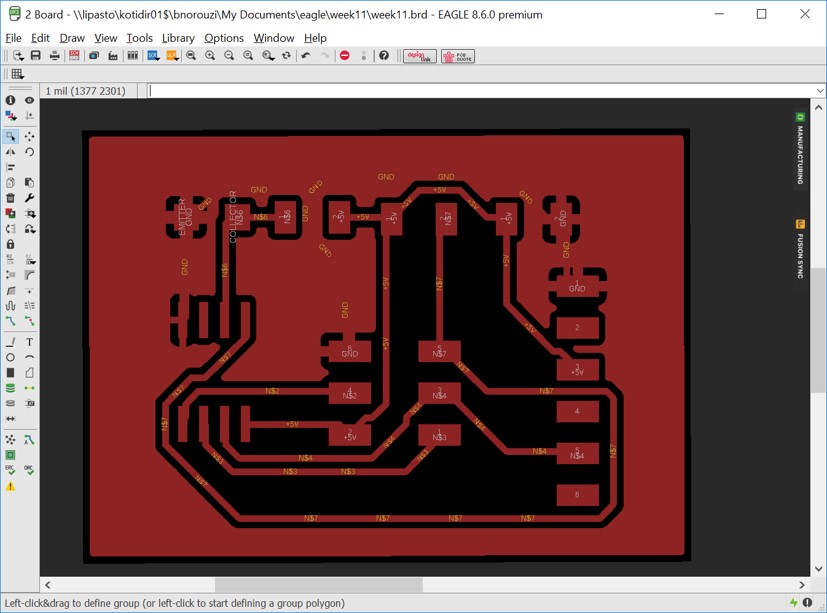
- When I created the board and started to move the componenets, orienting them was difficult so as Jari, fab lab instructor, suggested, I added 2 other components one for ground and attached it to grounds and the other for voltage and attached it to vcc. In this way, in my board view the grounds and vccs are named and orienting the components would be easier.
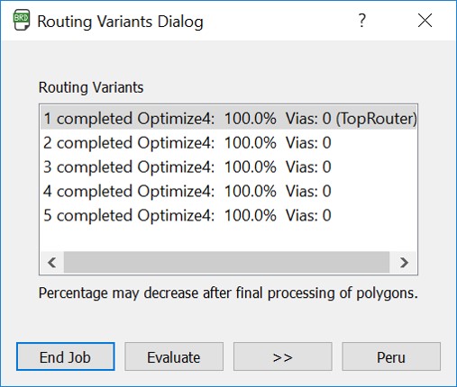
- I continueously used "Ripup; ratsnest; AutoRouter;" for replacing the components and optimizing the nets. And finally I succeeded in optimization.
- Preparations for exporting the traces and outlines as I explained the process in detail in Electronics Design week.
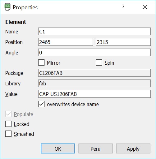
- Since 2 of the names were too long and out of the document border, I also overwrote device name for them in order to fit them in my desired space.
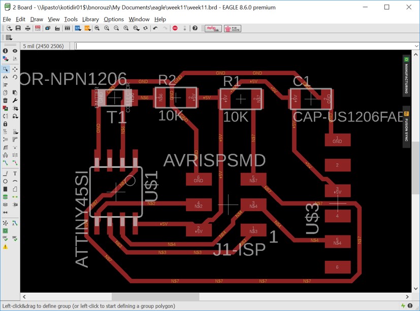
- Here is the result of the board design:
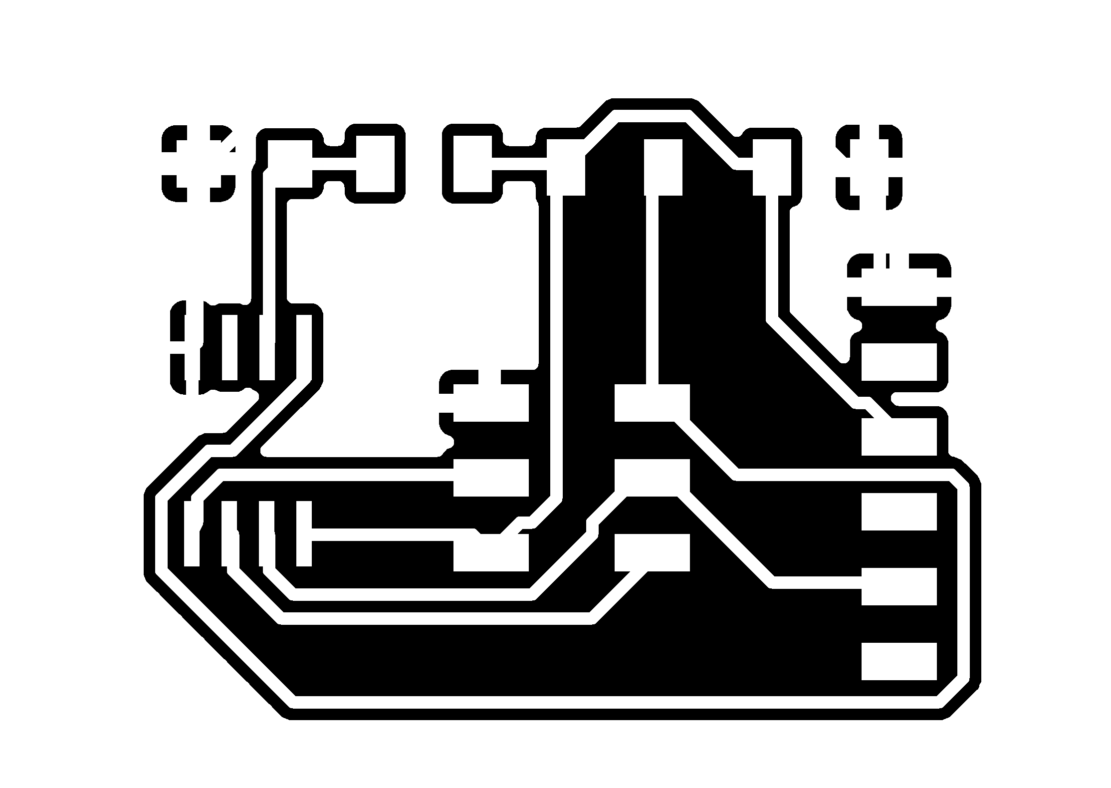
- The image of the traces:
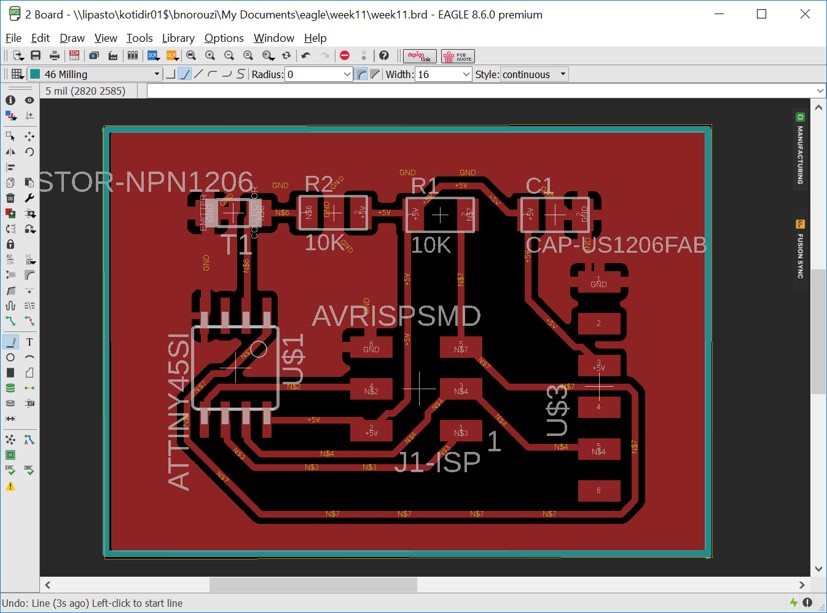
- The image of the outline:

Milling and Soldering
Since I have explained in detail the process of milling and soldering in Electronics Production Week, I just add some pictures as the result here:
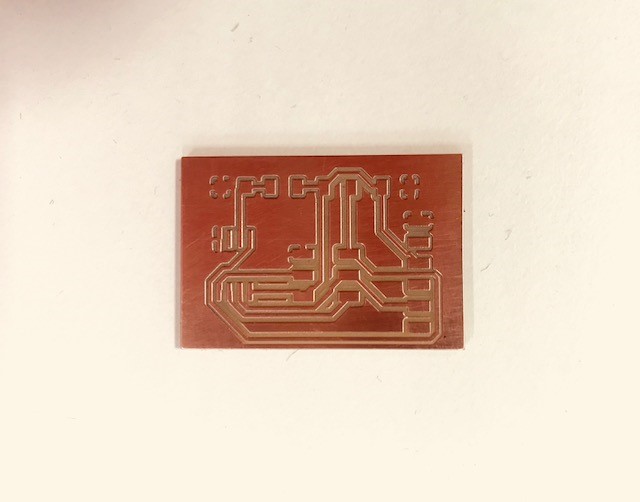
- The milled board:
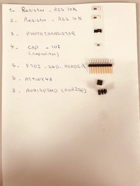
- The list of components:
- 2x Resistor 10K
- Photottransistor
- Capacitor 1UF
- FTDI Header
- ATtiny 45
- AVRISPSMD
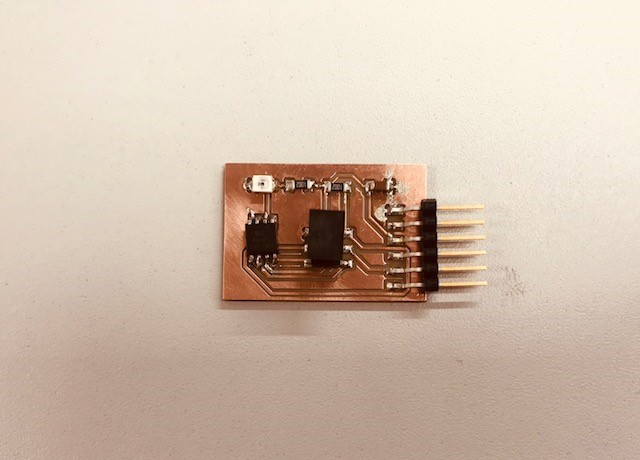
- The soldered board:
- Then I tested the board with multimeter for short circuits and it was OK.
Programming the Board
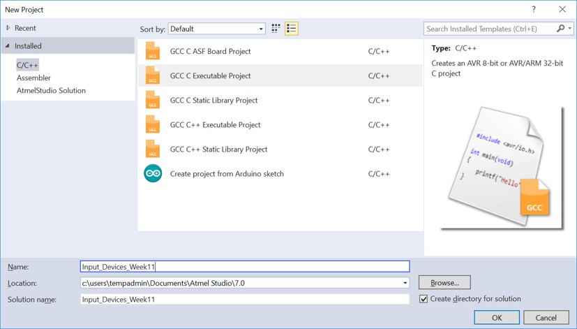
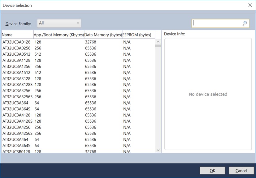
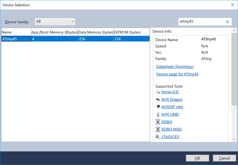
- Atmel studio (run as administrator) > create new project > selecting ATtiny 45
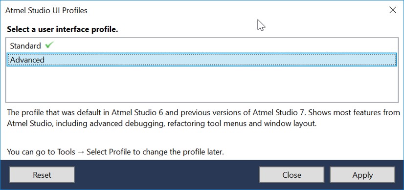
- I wanted to choose 'External Tools' from the 'Tools' tab but it did not appeared. So with the help of our instructor, Juha, we figured out that the problem is that the profile is set as standard. So I changed it to 'Advanced'. (Tools > select Profile > Advanced)
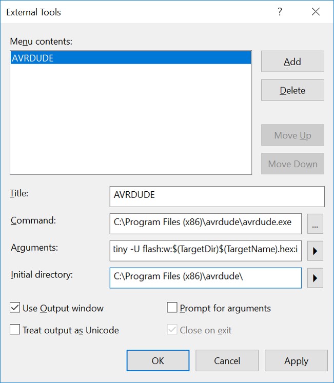
- Now Tools > External Tools:
- Title: AVRDUDE
- Command: C:\Program Files (x86)\avrdude\avrdude.exe
- Arguments: -p t45 usb -c usbtiny -U flash:w:$(TargetDir)$(TargetName).hex:i
- Initial Directory: C:\Program Files (x86)\avrdude\
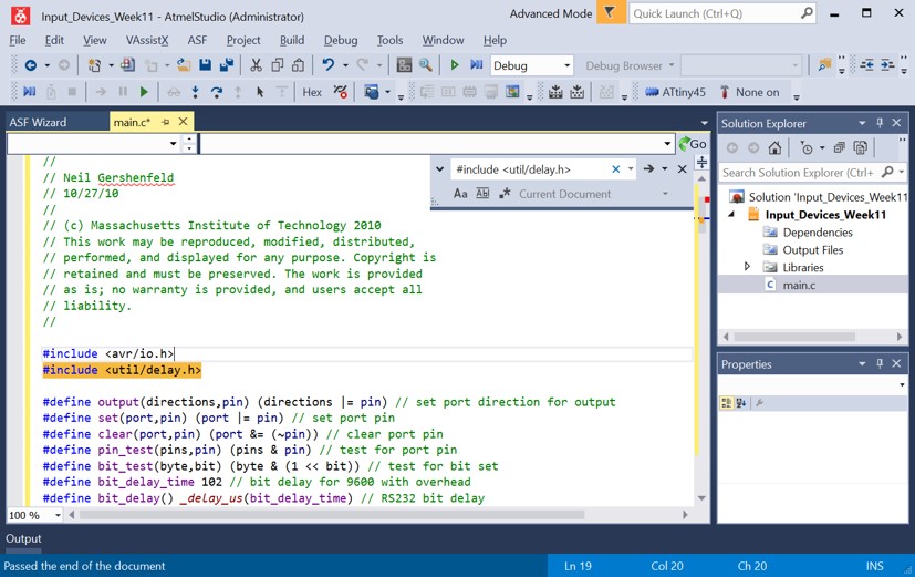
- The I copied Neil's code for hello.light.45.c
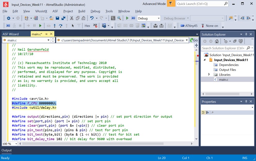
- Then I added
#define F_CPU 8000000UL
before the following line:
#include <util/delay.h>
to tell what is the speed of the Attiny45 microcontroller. This information about internal clock frequency was found on the datasheet. - Then I connected the board and programmer and computer (using FTDI cable and programming cable)
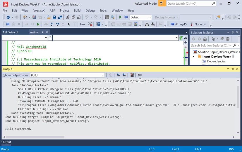
- Then in Atmel Studio: Build > Compile
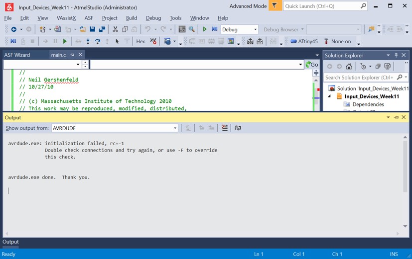
- Then Tools > AVRDUDE. And I had the following error:
initialization failed, rc=-1
Double check connections and try again, or use -F to override this check. - Now it was time to debug the issue.
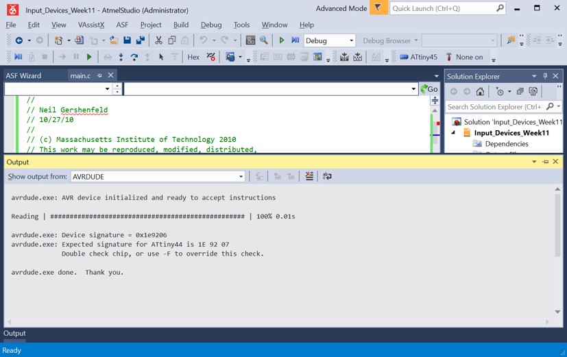
- I used our instructor’s (Juha) board and programmed it with my computer and it worked. So we came to the conclusion that there might be a problem with my board.
- With Juha, we checked the soldered components. And we identified some issues (e.g. a leg of ATtiny 45 that was not soldered properly to the board) that could be the problem and we re-soldered them. And I checked it again with (Tools > AVRDUDE) and it was not still working and I had the same error.
- With Juha, we we checked the schematic again and it was OK.
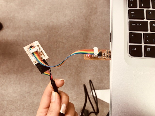
- As Juha suggested, I changed the orientation of the programmer and it worked. So I could say re-soldering and changing the orientation of the programming cable fixed this problem.
- The following picture shows the right orientation of my setting. (I put it here for my record)
- Now I installed Python for testing the light sensor. I first installed 'Python 3.6.5' but then I replaced it with 'Python 2.7.14'. Becuase at some point I faced the problem and Jari, another FabAcademy student, suggested changing the version would help.
- Now I just connected FTDI cable to the sensor board and removed the programmer.
I saved 'hello.light.45.py' from Neil's page.
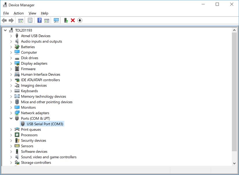
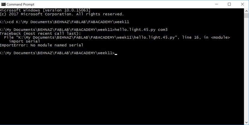
I saved it in a folder. Then I opened Command Prompt and typed the location of this file. And now I noticed (with help of my friend Jari) that I need to know the Com port number to complete this command. My windows did not have FTDI Drivers installed and I was not able to see the ports. So I followed this documentation to install it. And then I could find Ports in device manager, which was com 3. - Again in cmd going to the location that 'hello.light.45.py' is saved and typing
hello.light.45.py com3
And this time I had the following error:
No module named serial
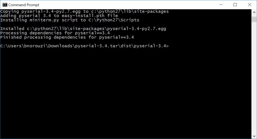
Which means I don't have a serial. - I installed pyserial. And good to have a look at Detailed Document.
- Unzipping the downloaded folder. Command Prompt > Going to the location that Pyserial is saved and 'setup.py' is there. In my case it was this location: C:\Users\bnorouzi\Downloads\pyserial-3.4.tar\dist\pyserial-3.4.
- Now typing the following command:
python setup.py install - Then again coming back to the location that 'hello.light.45.py' is saved and typing 'hello.light.45.py com3'. And it did not work again.
- My friend, Jari, gave me a suggestion based on his experience with the same issue: He believed that the problem is about the orientation of the Phototransistor. And he was right becuase after another Jari's help (Our instructor) with re-soldering this componenet, and testing again: it worked as you see in the video :)
Original Design Files
light_sensor_outline.rmlLight_Sensor_Traces.rml
week11.brd
week11.sch
.atsln file for the modified code
.c file for the modified code