Final Project - Development: LAMPBOT
The Final Week was came. Was time to build the project and pray that all skills I gained during fab academy give desired results.
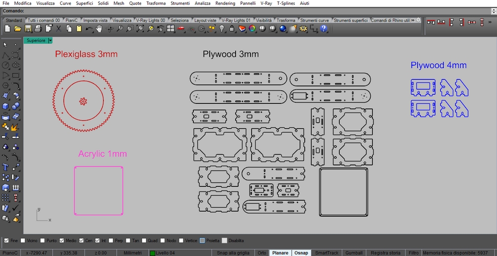
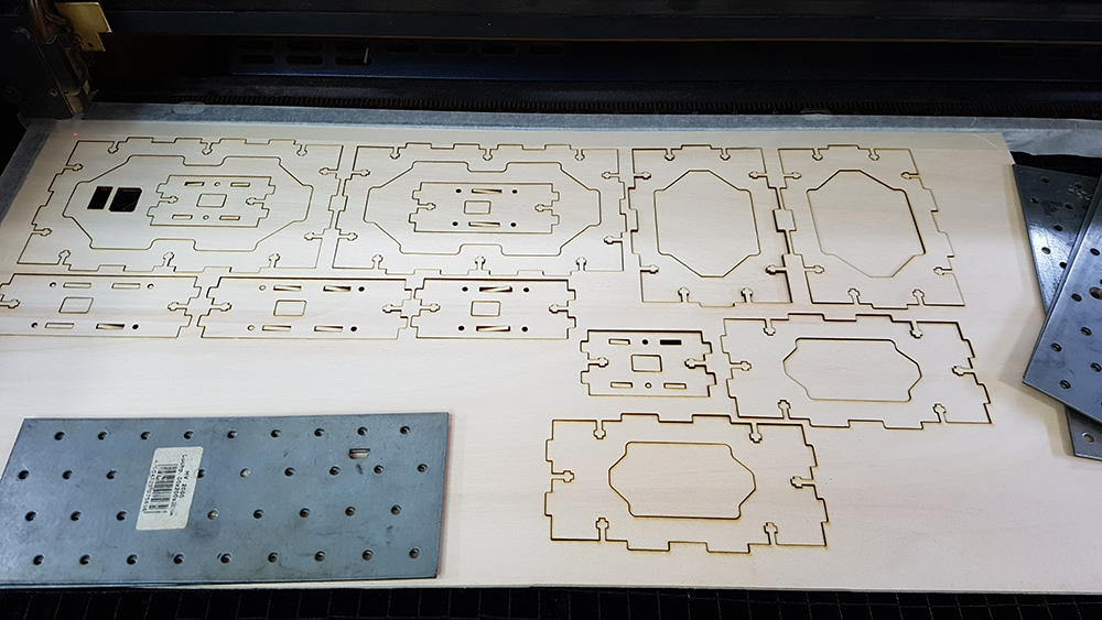
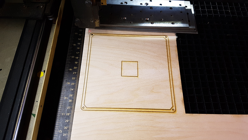
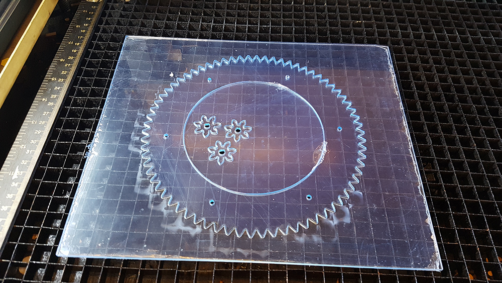
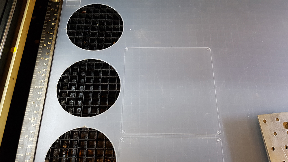
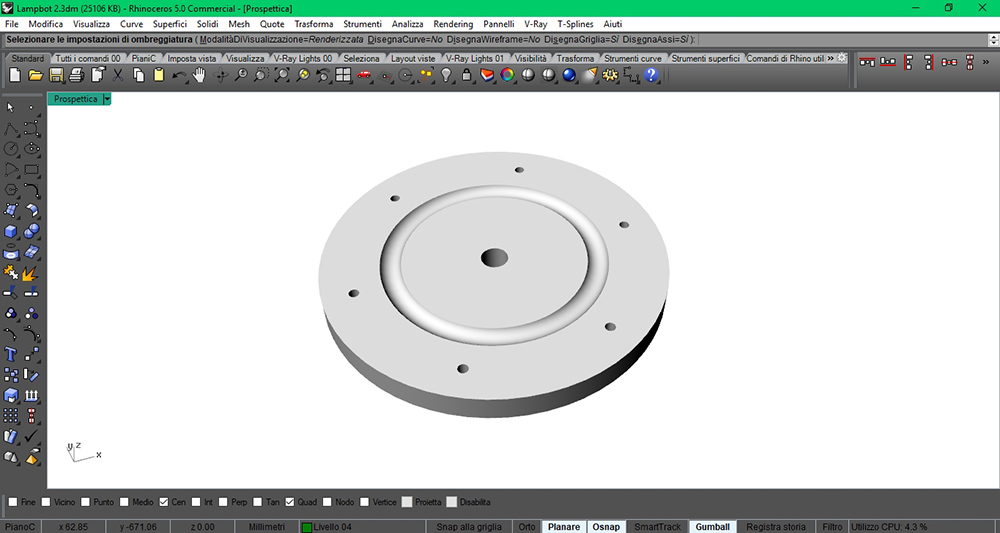
I prepared the dxf files in Rhino and I started to cut the pieces of my lamp's frame on the lasercut. I used 3 mm plywood for lamp frame, 4 mm plywood for the the pieces of servo motor holders at the base. Then I used 3mm plexiglass for gears and 1 mm opaline acrylic for the diffuser. I cut 3 pieces for each gear to reach 9 mm thickness.
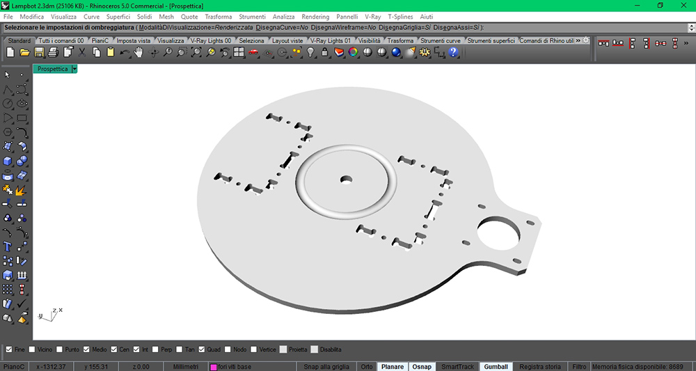
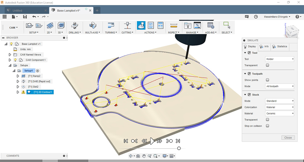
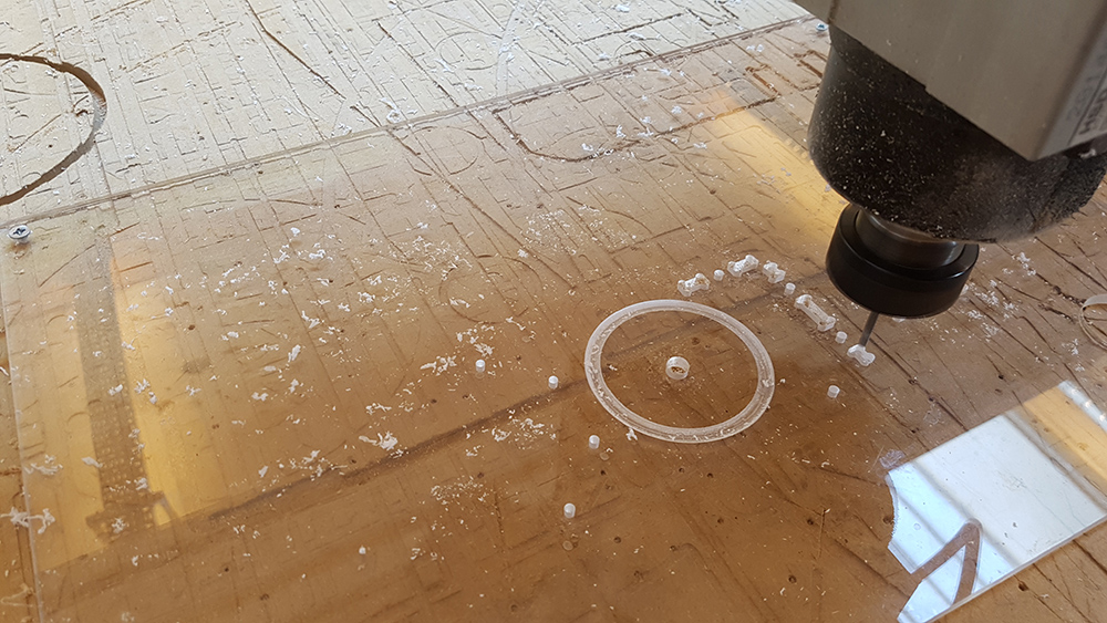
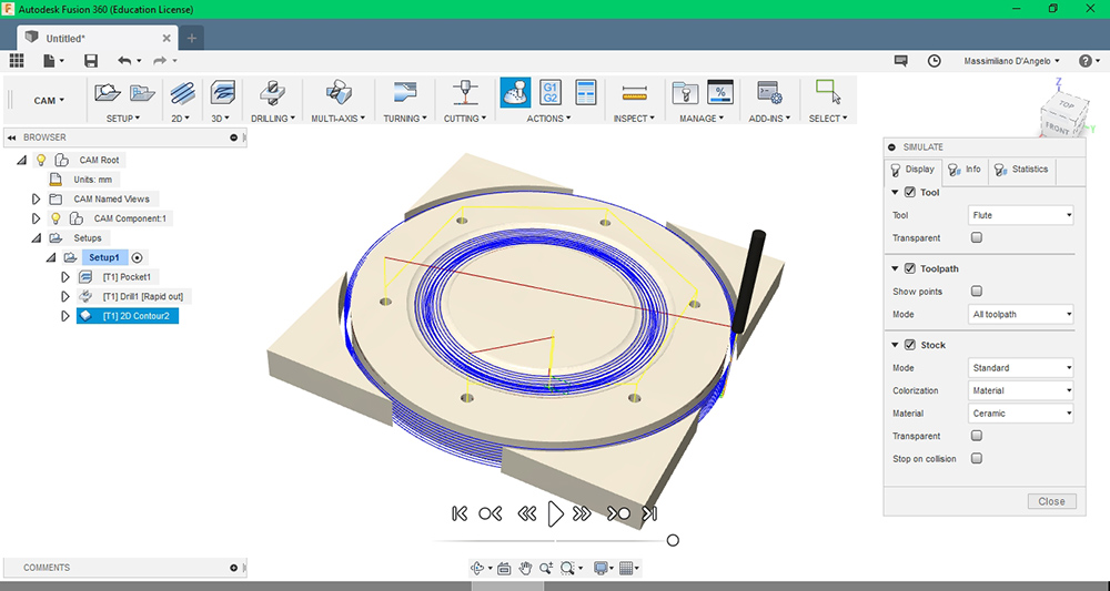
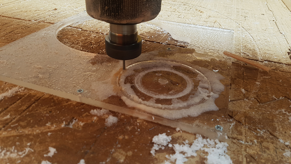
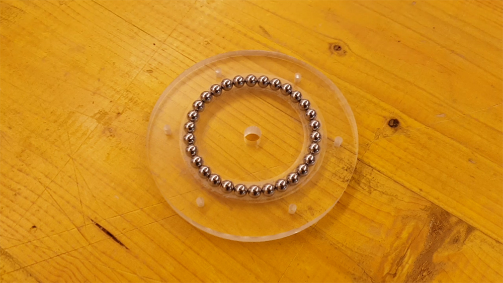
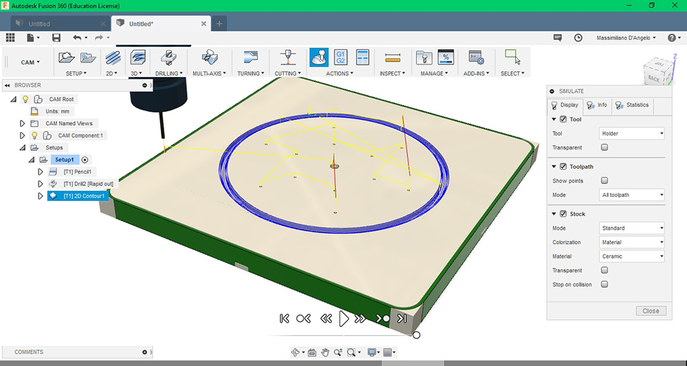
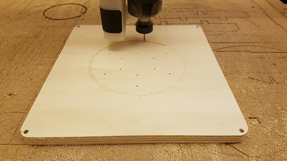
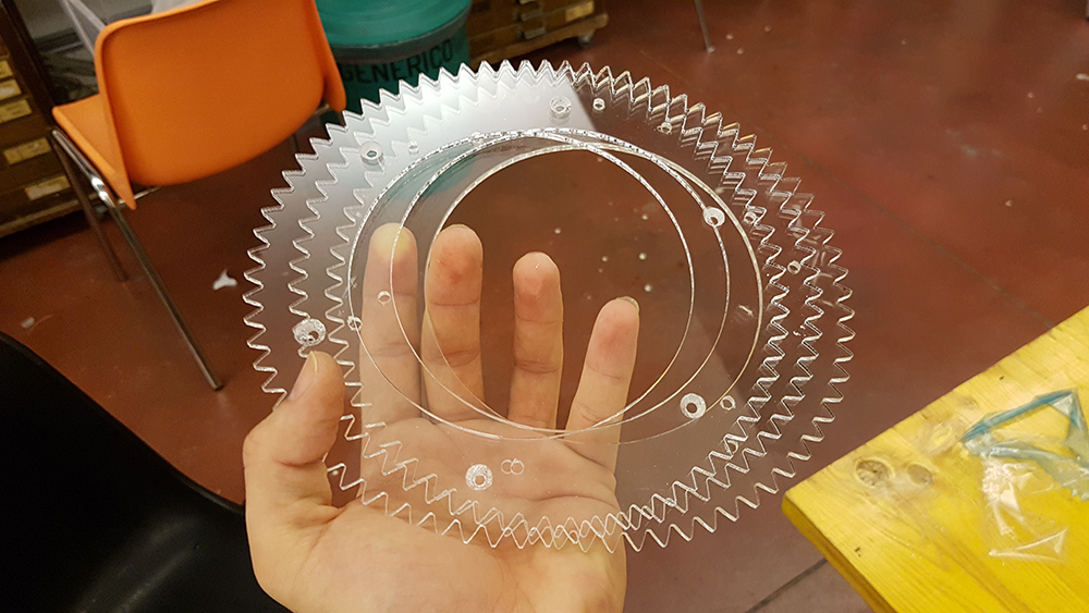
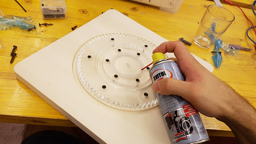
In order to avoid buy expensive bearing, I decided to build one by myself. I prepared on fusion the cam processes for the milling on Shopbot. I bought steel spheres with 6,35mm diameter, and I milled a circular groove on the two parts of the base, with plexiglass 8 mm thick. I used water to avoid overheating of the tool.
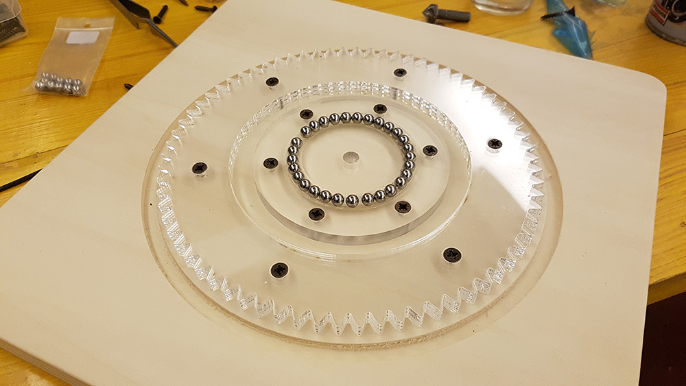
With spheres it worked perfectly.
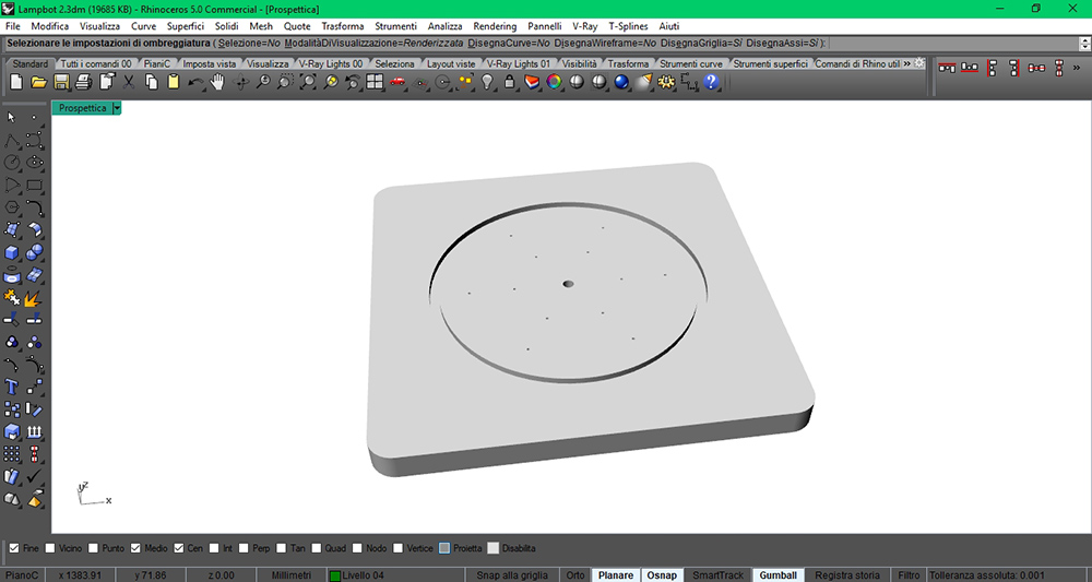
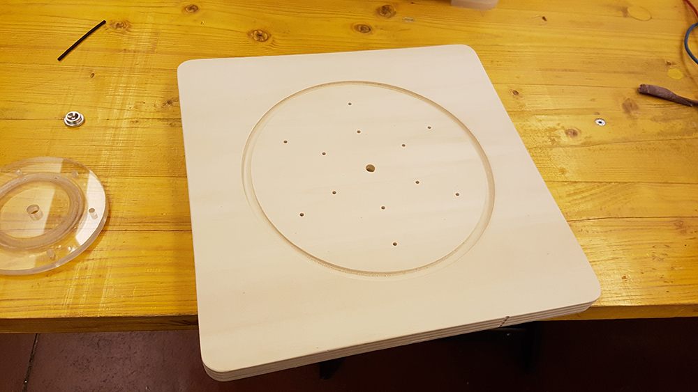
Then I milled the fixed base on the 20 mm wood.
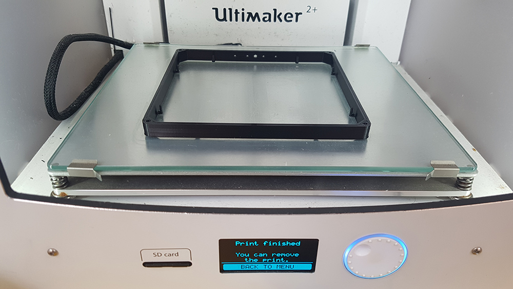
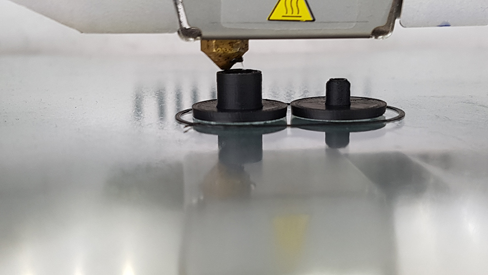
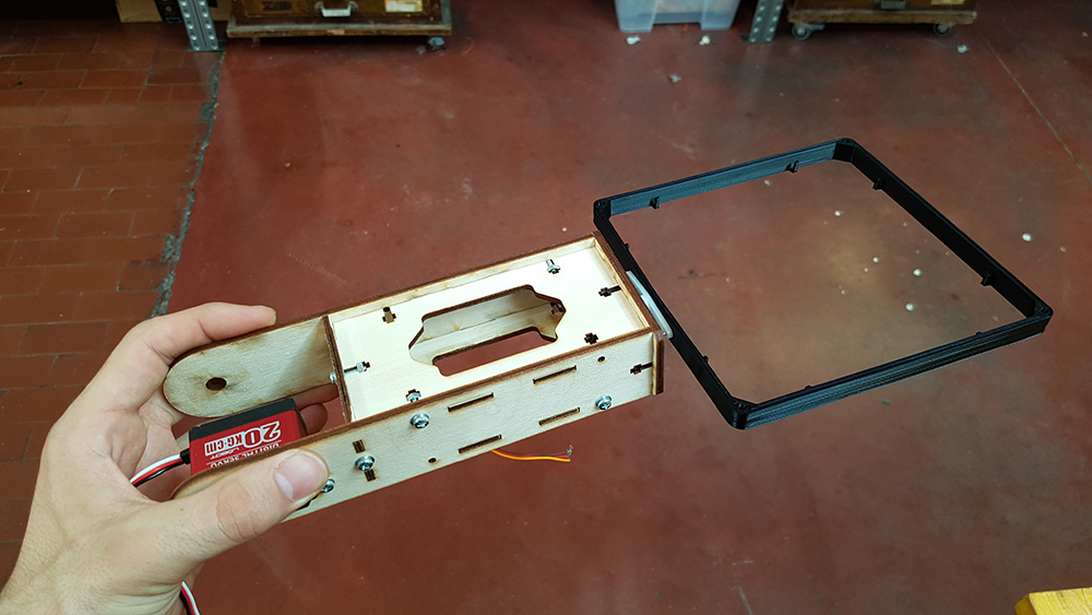
Now was time to print the diffuser and the hinges.
At this point I had almost all the parts to build the lamp.

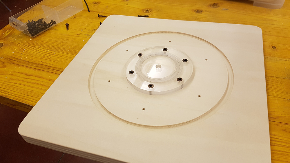
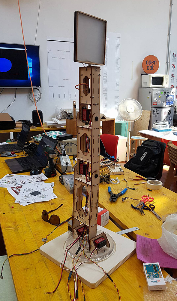
I started to assembly from the base. I mounted on it the lower part of bearing and the bigger gear.
Then I added some grease compatible with plastic and put spheres inside the grooves and
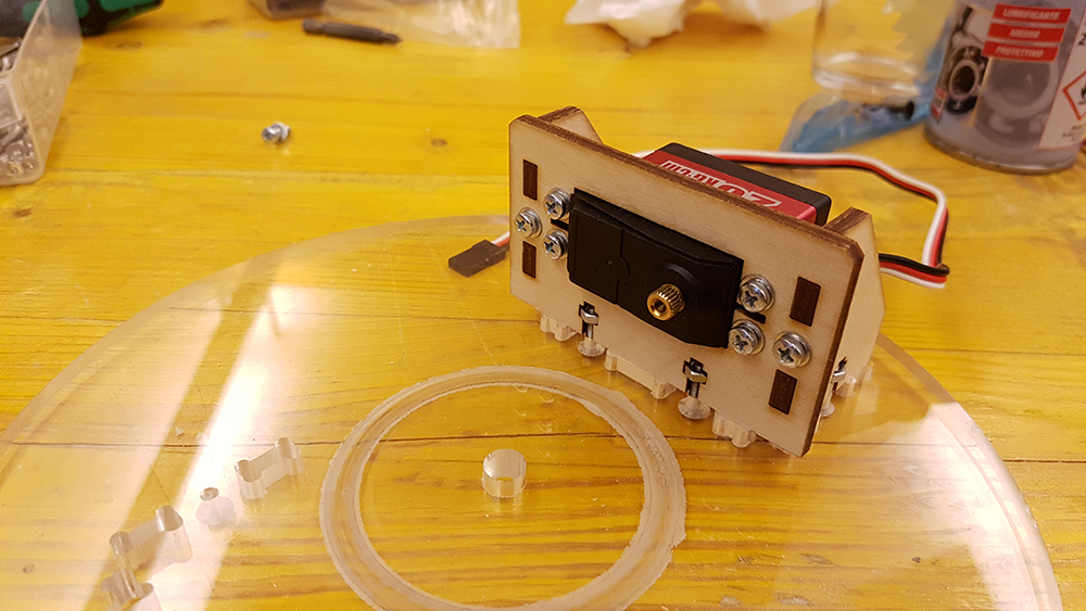
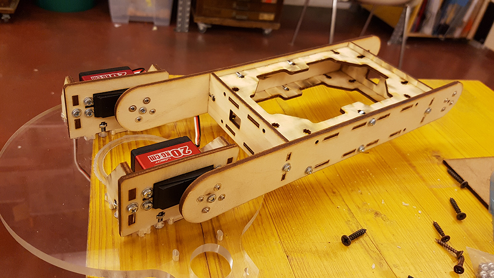
After fixed base, i aseembled the first servo motor holders on the revolving plate at the base.
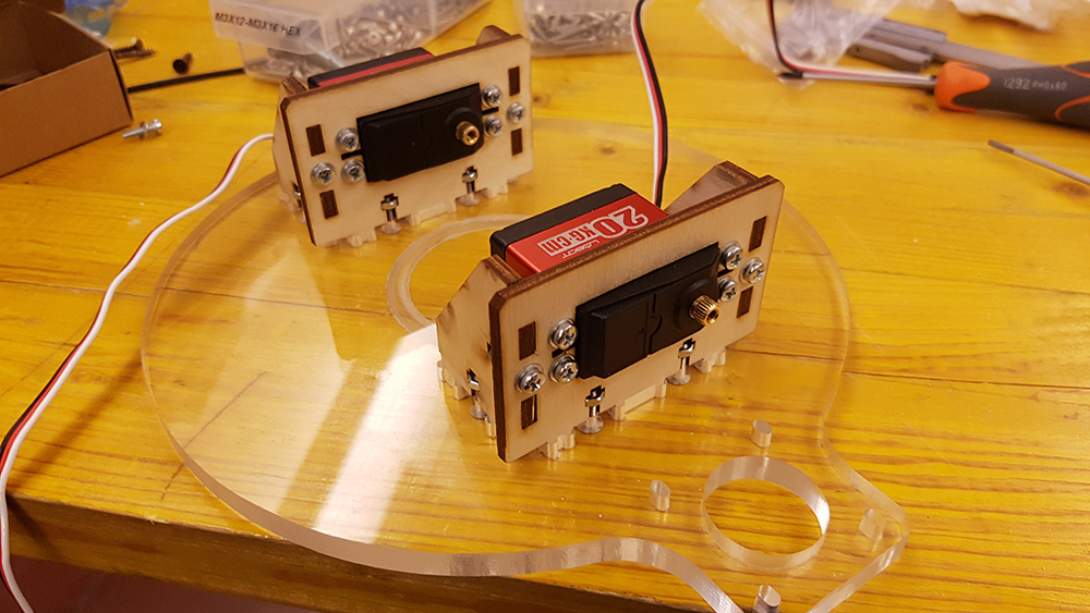
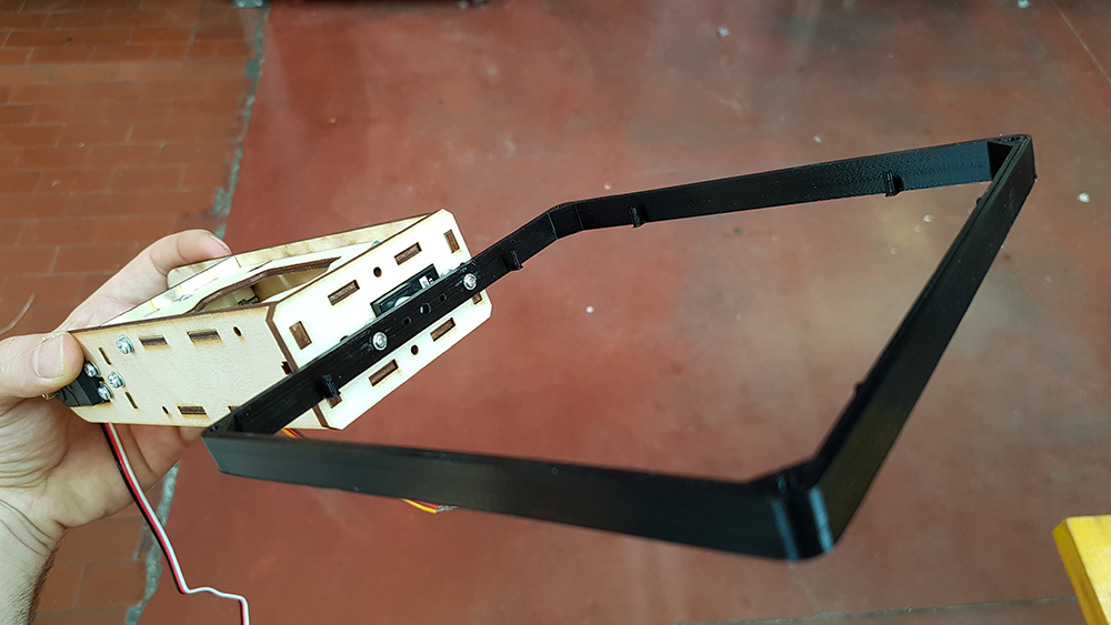
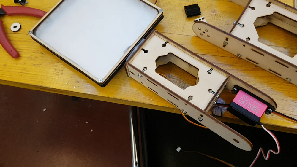
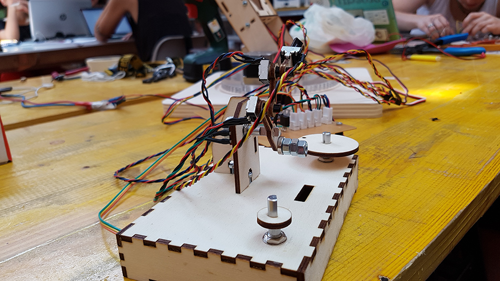
I continued assembling the frame of lamp.
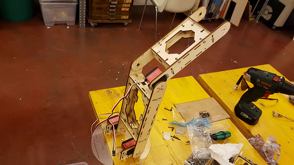
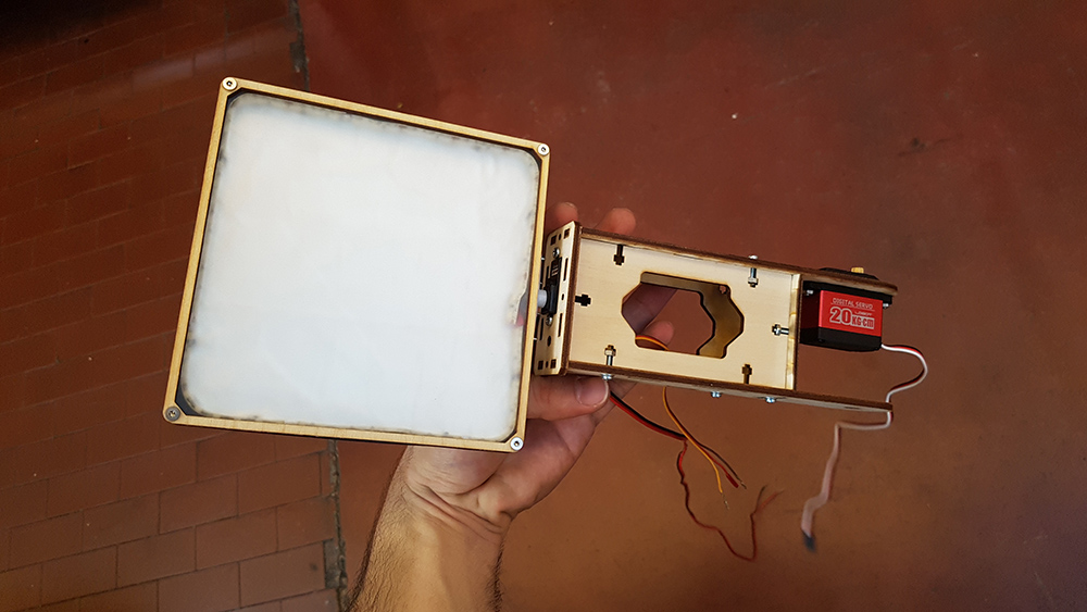
The last arm of lamp, support the diffuser of lamp. So I assembled it apart.
On the frame of diffuser I attached the stripled. I used the system that is used in LED panel tecnology. That allow me to obtain a soft and uniform light, very close to a little soft box effect. So I put the opaline acrylic piece on the front of the diffuser.
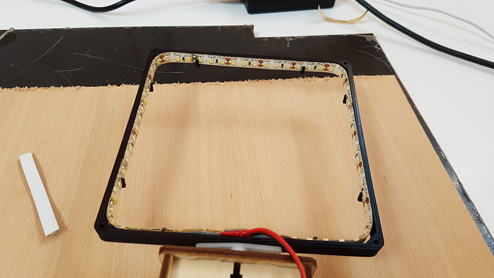
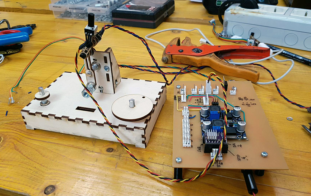
Then I made a test to see if LEDs work well. I connect to power supply and... I had the light!!!
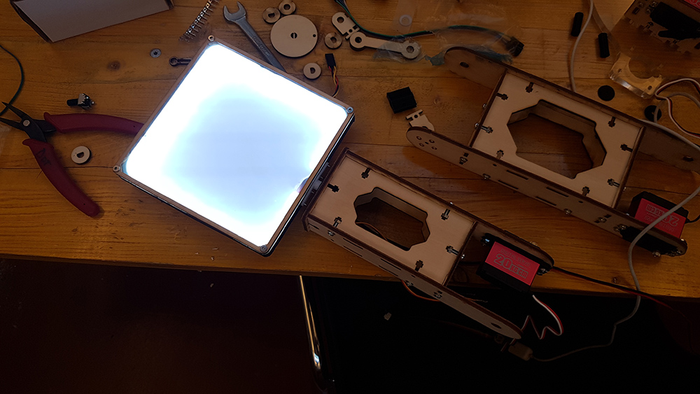
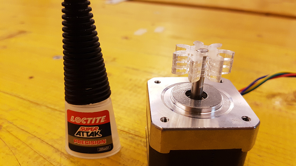
At last I glued the small gear pieces and put them on the stepper.
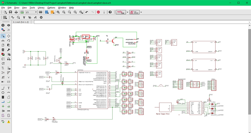
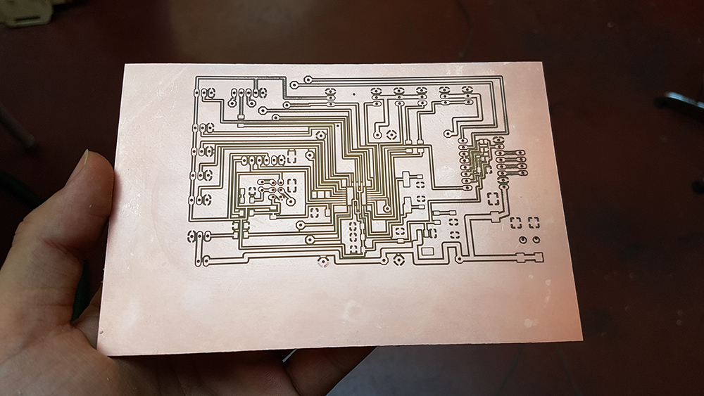
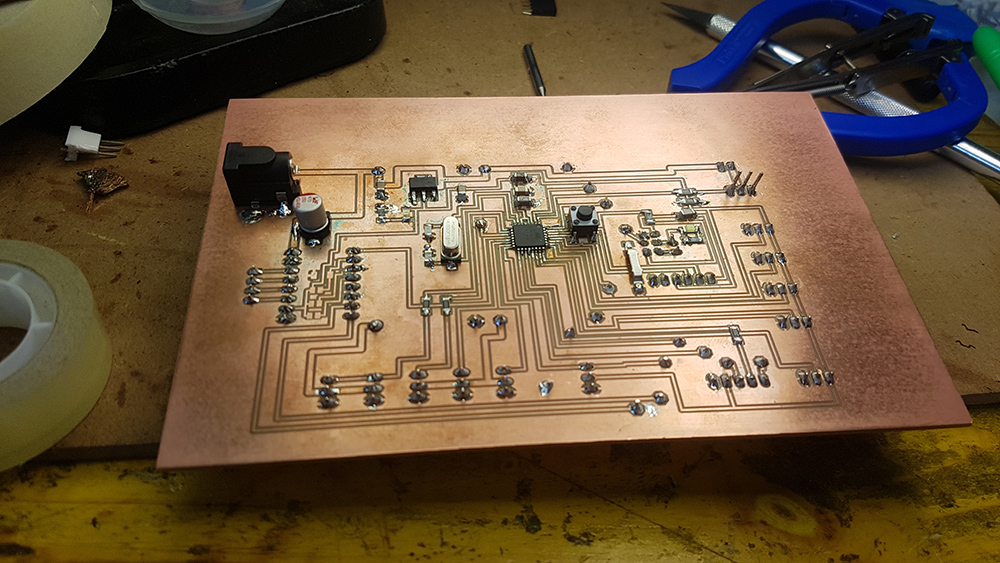
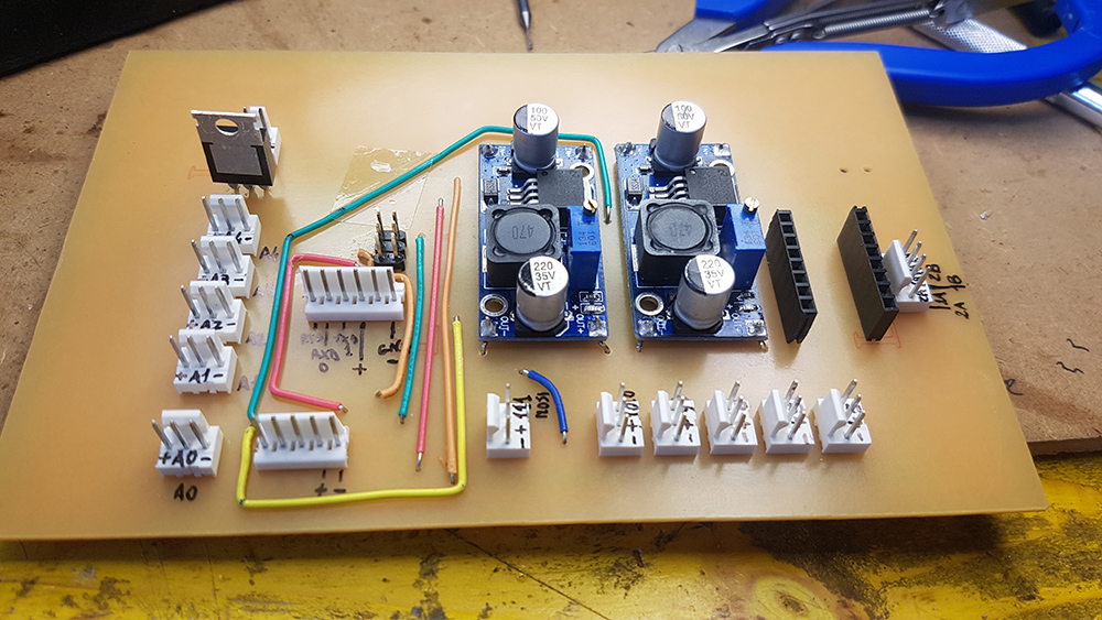
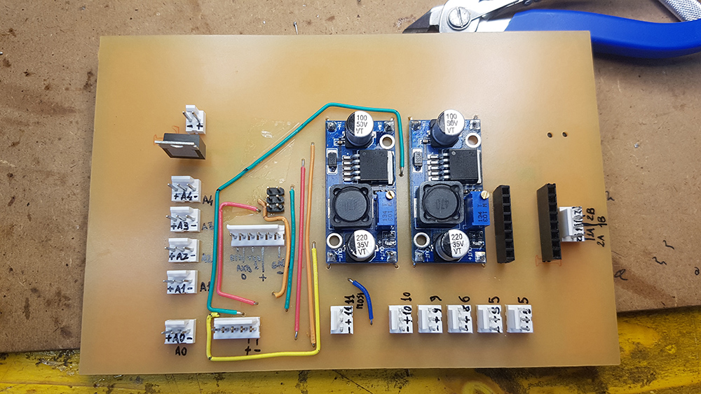
Now was time to made the electronic board. I designd it in Eagle, by this time I was a very expert in Electronic design. I start from satshakit by Daniele Ingrassia. I choose to use through hole pin header connectors, because they are more resistant that smd ones. I used both the faces od the PCB. On the face with copper layer I put all smd components and the reset button and status and power LED. On the other side face I put all the connectors and the DC /DC converters, so that i can use just this face for all the connections. I needed DC/DC connectors because the servos works at 6,5 Volts and have absorption peaks until to 1.0 Ah when i quickly change the direction of rotation. So I buyed two LM2596 DC/DC converter that can reduce voltage from an input 4 - 35 V to an output 1.23 - 30 V and support until to 3 Ah. I setted them to work at 6,5 Volts, that was a good tension for my Servos.
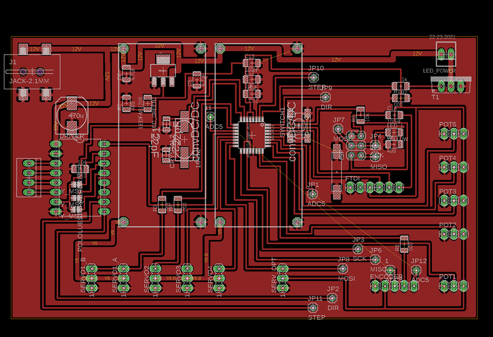
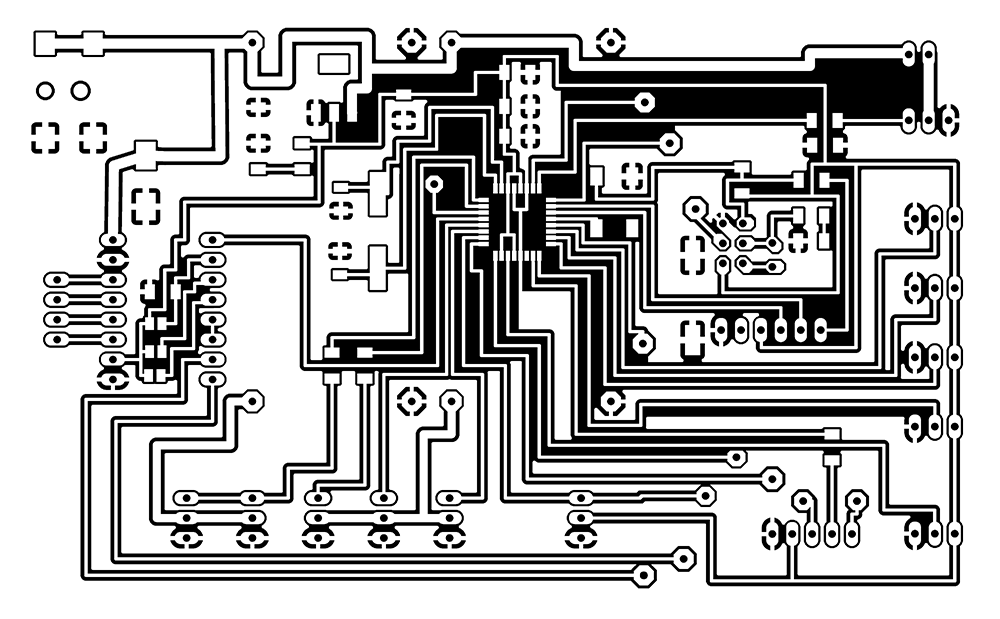
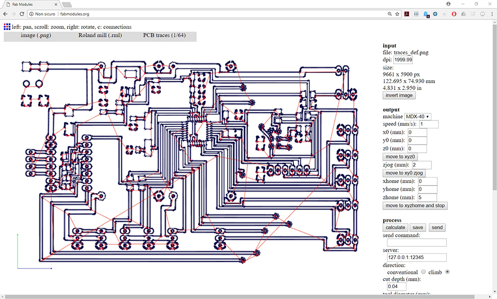
Then I processed it on fab modules and milled it on the Roland MDX-40. I had a great result.
Finally I started soldering all the components.
After that, I designed the controller. I used the same linkage and proportion between arms as on the lamp, but here I put potentiometers in the revolving joint, so that moving it i can move the lamp in the same way. The potentiometers had a very low friction, so I needed to design the arm linkage very very light. on the first arm i put some nuts as counterweights, to mantein the position when you remove your hand by the controller. On the box of controller i put a wheel for the potentiometer that control the LED brightness and an encoder for the stepper position on the base.
After that I start to write the code. I was able to write a code for controll Servos and the LED, and another one for controll the stepper. They work well when uploaded stand alone on mictrocontroller. Unfortunately I didn't find the way to match the two codes in a single one, but i know I can solve this problem using "millis" variable instead of "delay" and creating an interrupt in which run the encoder script. In the future I will develop this part.
Here the code of Encoder
      #define stepPin 4
      #define dirPin 2
      #define outputA A0
      #define outputB A5
      int counter = 0;
      int angle = 0;
      int aState;
      int aLastState;

      void setup() {
      // Sets the two pins as Outputs
      pinMode(stepPin,OUTPUT);
      pinMode(dirPin,OUTPUT);
      pinMode (outputA,INPUT);
      pinMode (outputB,INPUT);

      aLastState = digitalRead(outputA);

      }
      void loop() {
      aState = digitalRead(outputA);

      if (aState != aLastState){
      if (digitalRead(outputB) != aState) {
       counter ++;
       angle ++;
       rotateCW();
      }
      else {
       counter--;
       angle --;
       rotateCCW();
      }
      if (counter >=30 ) {
       counter =0;
      }


      }
      aLastState = aState;
      }
      void rotateCW() {
      digitalWrite(dirPin,LOW);
      digitalWrite(stepPin,HIGH);
      delayMicroseconds(2000);
      digitalWrite(stepPin,LOW);
      delayMicroseconds(2000);
      }
      void rotateCCW() {
      digitalWrite(dirPin,HIGH);
      digitalWrite(stepPin,HIGH);
      delayMicroseconds(2000);
      digitalWrite(stepPin,LOW);
      delayMicroseconds(2000);
      }
And here the code for control servos and LED, reading potentiometers
      #include

      Servo myservo1;
      Servo myservo2;
      Servo myservo3;
      Servo myservo4;
      Servo myservo5;
      Servo myservo6;

      int potpin = A6;
      int potpin1 = A1;
      int potpin2 = A2;
      int potpin3 = A3;
      int potpin4 = A4;
      int knobvalue;
      int val;


      void setup()
      {  pinMode(3, OUTPUT);
        myservo1.attach(5);
        myservo2.attach(6);
        myservo3.attach(9);
        myservo4.attach(10);
      }

      void loop()
      {
        knobvalue = analogRead(potpin4);
        knobvalue = map(knobvalue, 0, 1023, 0, 255);
        analogWrite(3, knobvalue);

        val = analogRead(potpin);
        val = map(val, 0, 1023, 0, 250);
        myservo1.write(val);
        delay(15);

        val = analogRead(potpin1);
        val = map(val, 0, 1023, 0, 250);
        myservo2.write(val);
        delay(15);

        val = analogRead(potpin2);
        val = map(val, 0, 1023, 0, 250);
        myservo3.write(val);
        delay(15);

        val = analogRead(potpin3);
        val = map(val, 0, 1023, 0, 250);
        myservo4.write(val);
        delay(15);
      }
At the end I assembled all the lamp and connected the cables, I programmed the board and the lamp worked very great, with my great satisfaction :D .
Video:
Download
You can download DXF files here:
You can download 3D files here:
You can download Eagle files here:
You can download Arduino codes here: