04. Electronics Production
Group Assignement
- Characterize the specifications of your PCB production process.
Individual Assignement
- Make an in-circuit programmer by milling the PCB.
Characterize your PCB production process.
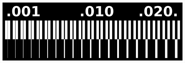
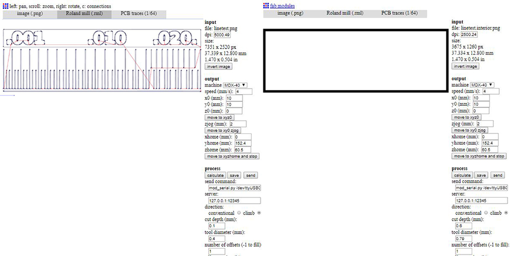
In this week we've learned how building a PCB board by ourself with varius kind of technology processes. To product our programmer, we've chosen to work with milling machine, that we have in Opendot is the Roland MDX-40. So first step was to characterize the machine to evaluete what level of detail we could reach. We have downloaded two png files, one for traces and one for cut. We must remember that the machine save only the white parts of the picture and mills the lack parts (always the fle are pictures in black and white). We have uploaded them as input on Fabmodules, to calculate the .rml outputs, the path instructions to give to machine. So we selected "Roland Mill" as otuput and "PBC traces 1/64" as process.

When we selected "Roland-MDX40" in "output", the format of settings was almost completly pre-filled. For trace test, just we selceted in "speed": 4 mm/s, in "cut depth": 0,1 mm and in "tool diameter": 0,4 mm, the we saved the .rml output file on an usb pen-drive. While for cut test the settings was almost the same. just we changed "diameter tool" to 0,79 mm, and "cut depth" to 0,6 mm.
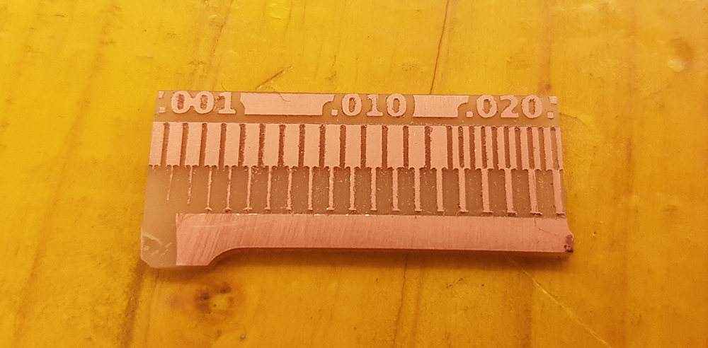
Once we had the .rml files, we could move to pc connected to milling machine. We payed much attention in mounting the 0,4 mm tool, because these kind of tools are very delicate. We upload the trace file first on vPanel software. With a double-sided adhesive tape we fixed the PCB piece to the sacrifical plane. It must be very planar. We set the home origin of three axes, using for Z axis a very smart tool, made in Opendot, that use a LED to advise tool are touching the PCB board. So we started the milling of trace. After that, we changed the tool with a 0,79mm one and started the cut. All worked perfectly, and we could see that machine has a very good resolution for traces, until to 0,04 mm, that is perfect to milling our programmer.
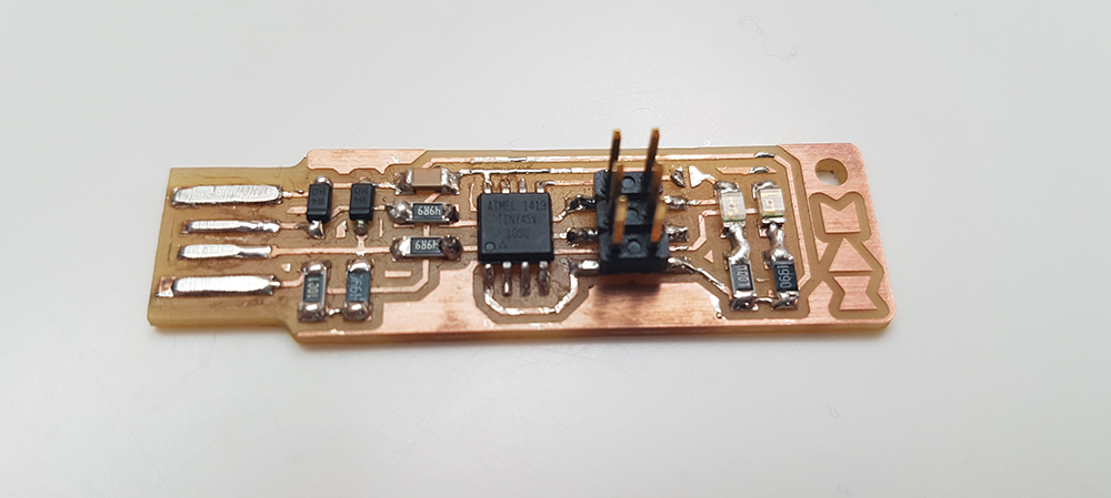
Make an in-circuit programmer.
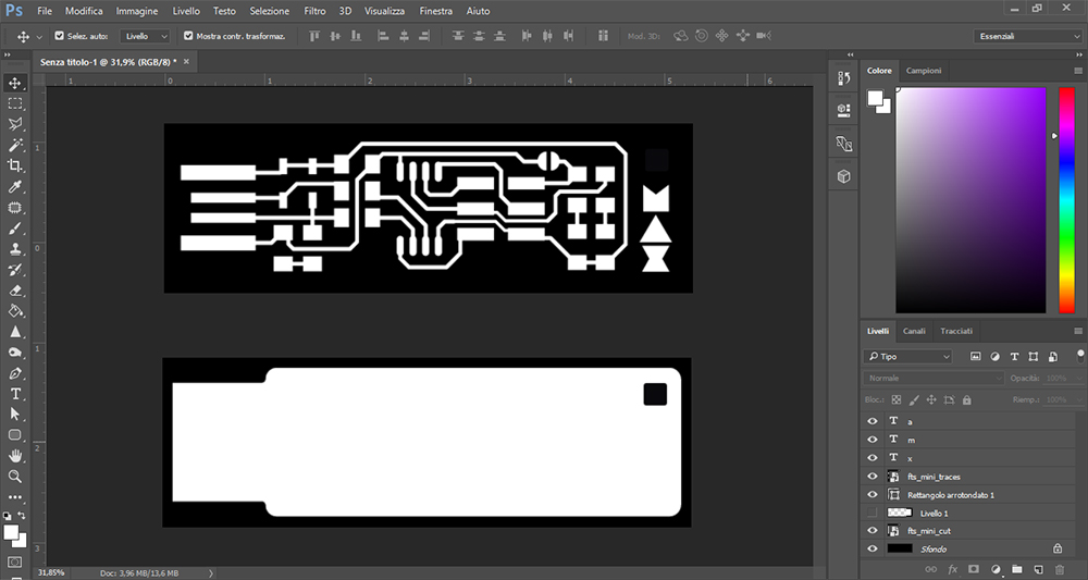
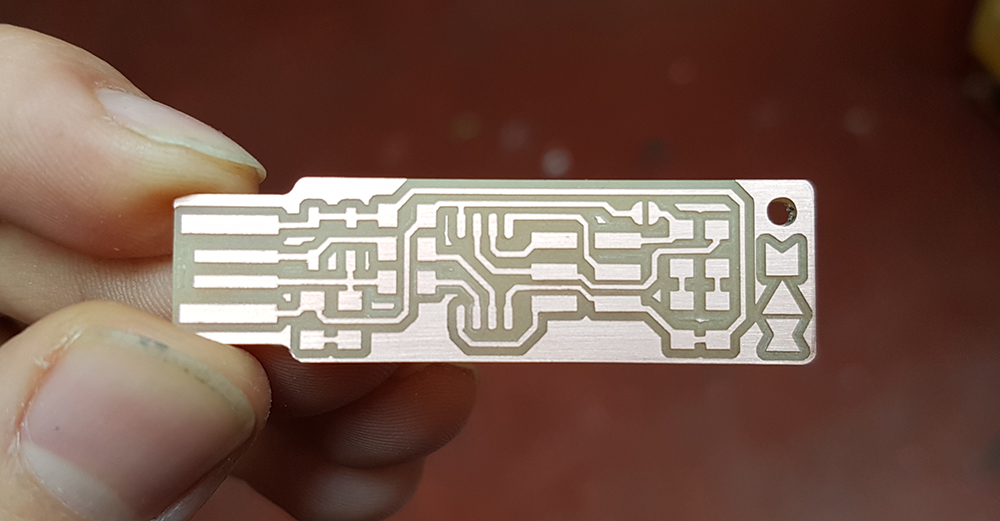
To make my personal programmer, I followed Brian's tutorial, one of that suggested by Fab Academy using an ATtiny45. Here too, I downloaded two files, one for traces and another one for cut. Remembering that the machine save the white part of picture, I decided to customize my programmer, putting the logo of my name on the png of traces, and a little hole in the cut picture, so i could put a little chord to attach it to the clip of my bag (so I can't forget it).
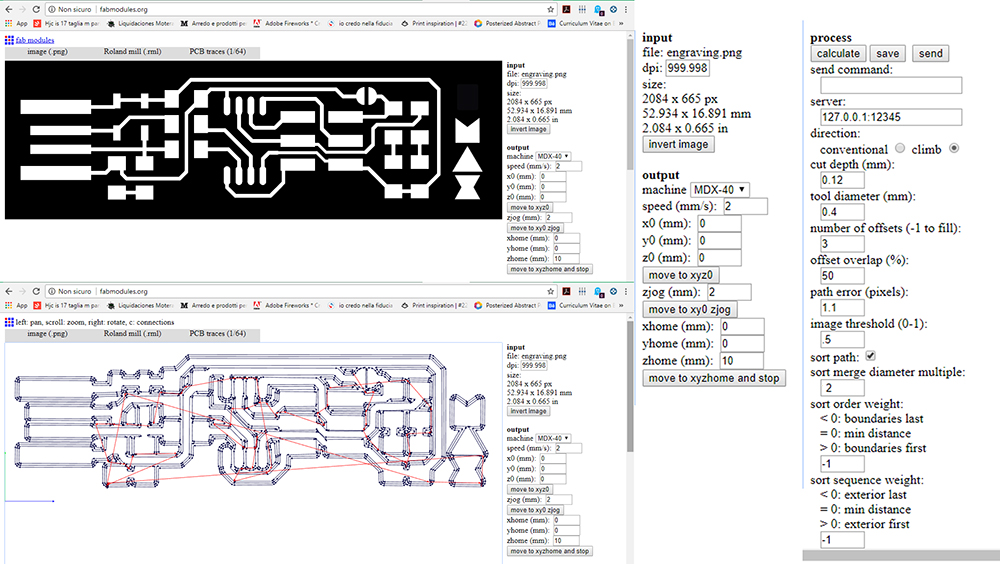
I uploaded the two png on fabmodules. Starting from the trace file, I setted the parameters as shown in the following screenshots. The "speed" was 2 mm/s, all the axis to 0 because I gave the home in "vPanel", the machine's software. The "tool diameter" was 0,4 mm, "cut depth" 0,12 mm and "number of offsets" was 3.
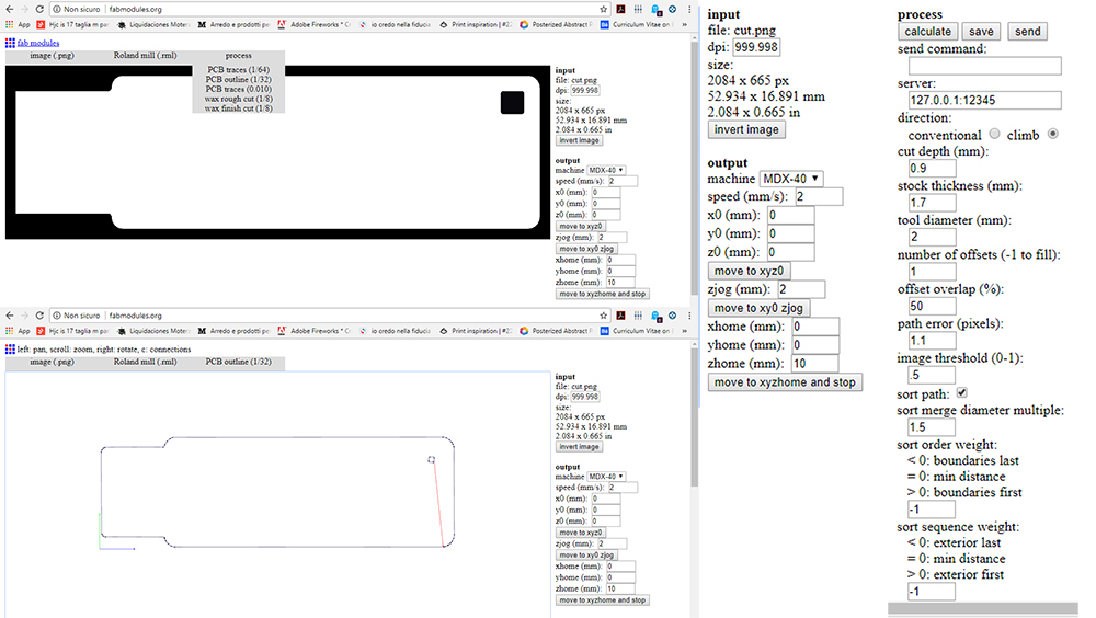
For the cut, I changed the "tool of diameter" to 2 mm, the "Number of offsets" to 1, and the "cut depth" to 0,9. Then I exported both the files on an usb pen-drive
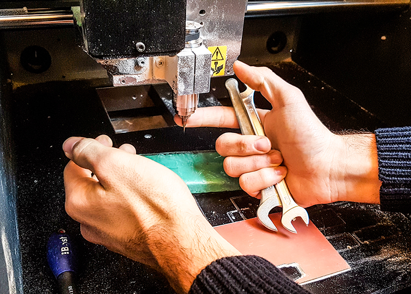
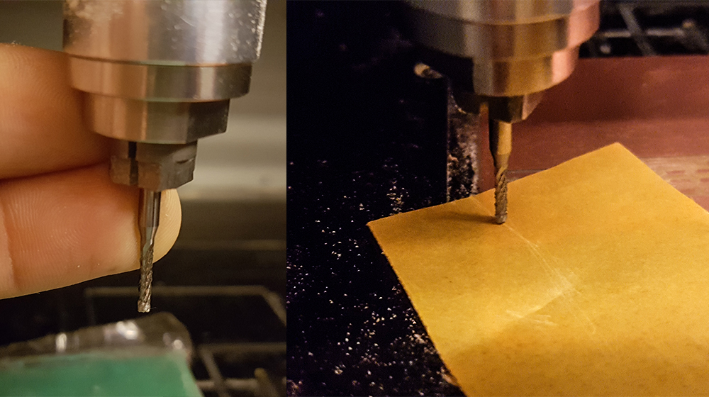
On milling machine, I mounted the 0,4 mm tool. For safety of tools, during the mounting I put a play dough brick under the spindle, to prevent damage if tool falls down.
In Roland vPanel I setted the rotation speed to 15000 rpm, the home of "x" and "y" axes. The machine starts from the left-bottom corner.
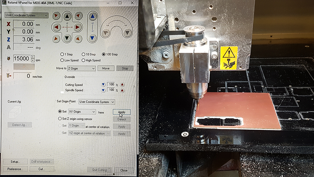
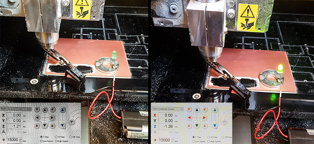
Setting the "z" axis origin is just a little bit harder than other axes, because if you move down the tools too quikly, you can risk to touch and damage the tool against sacrifical plane. So you must move the "z" very slowly. To be sure that the tool just touch the PCB without pressing too much, I used the special Opendot's sensitive indicator. I put the washer connected to LED's anode on PCB piece, and attached the crocodile clip connected to cathode on the tool. All the system is powered by A2 batteries pack. In this way, when the tool touch the board, the LED lights up.
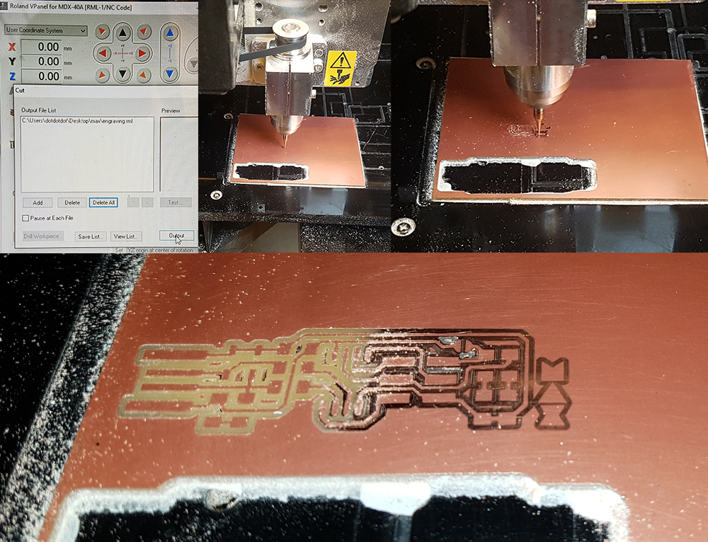
Once I have setted the origin of three axes, I launched the milling process selecting the Trace file (renamed "engraving") in "Output" and then pressing on "Cut". Instantly I noticed that something went on wrong. The tool didn't go down enaugh on the right side of the PCB board, and failed to mill the copper layer. That because the PCB board is not planar perfectly, but a little bit lower on the right side.
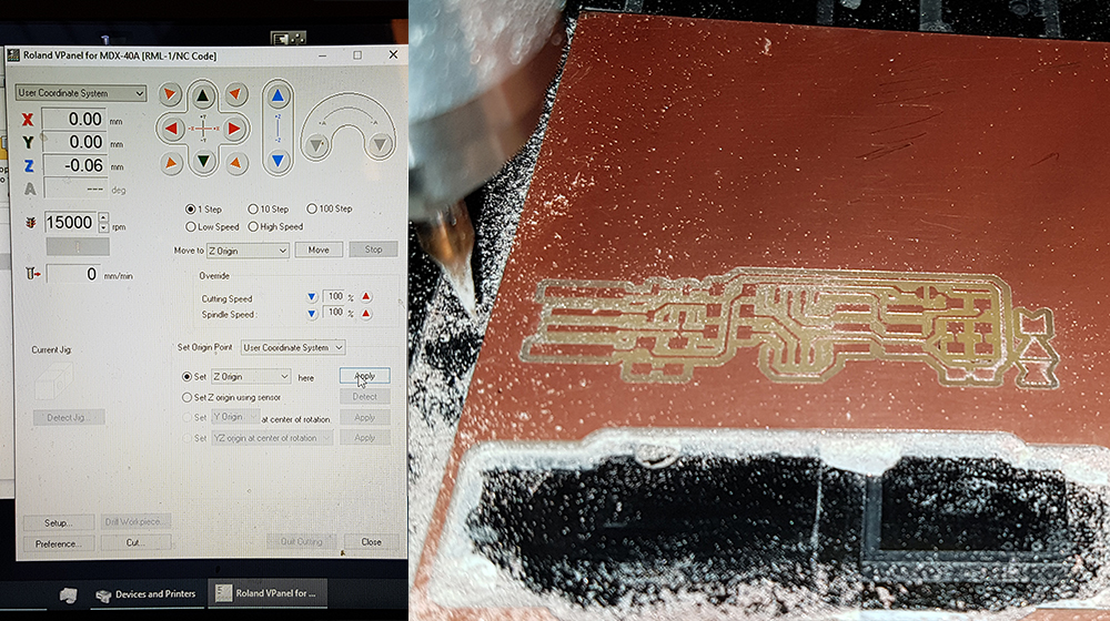
To reach to mill correctly all the traces of my board, I put 0,06 mm down the z axis home and re-launched the cut. Now the milling process was perfect.
After the milling of traces I was ready to cut the outline of my board. I changed the tool and mounted a 2 mm diameter one. To set the origin of "z" home was not necessary a so high precision. So I put a piece of paper that have a 0.1mm thickness, between tool and PCB. The cut depth value 0.9 mm ensured the success of cut.
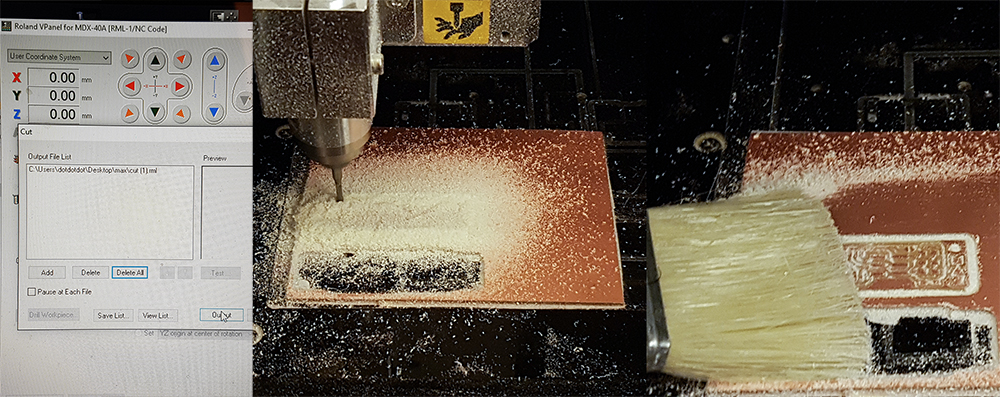
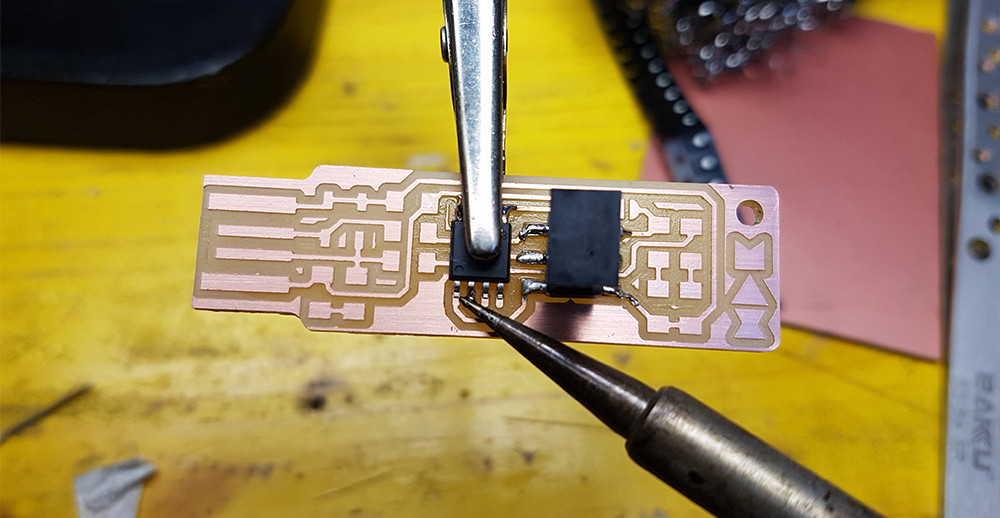
After the cut, I removed the board from the sacrifical plane and wiped away the double-sided adhesive tape. I've cleaned the traces with a piece of sandpaper (800 grit). I was ready to soldering.
Soldering was quite hard, because of thiny component to solder on board. That the complete list:
- 1x ATtiny45 or ATtiny85
- 2x 1kΩ resistors
- 2x 499Ω resistors
- 2x 49Ω resistors
- 2x 3.3v zener diodes
- 1x red LED
- 1x green LED
- 1x 100nF capacitor
- 1x 2x3 pin header
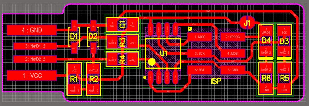
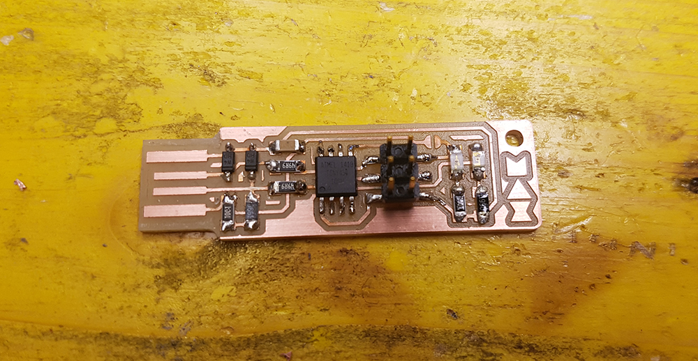
At this point I created with solder a little bridge on the jumper near the ISP header. In this way the header can be used to program the tiny45. Once it was programmed, I removed the bridge to turn the board into the programmer rather than the programmee.
Next step was the programming of the board.
Following this tutorial I started with installation of three software:
- Atmel AVR Toolchain for Windows Installed in C:\Program Files
- GNU make
- Avrdude Installed in C:\Program Files
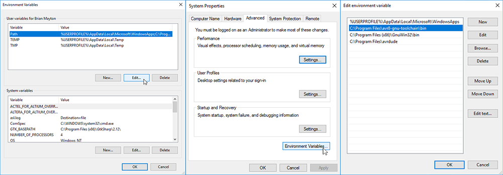
Then I've edited the environment variable under the path: Start > Control Panel > System > Advanced System Settings > Environment Variables, adding the following values:
- C:\Program Files\avr8-gnu-toolchain\bin
- C:\Program Files (x86)\GnuWin32\bin
- C:\Program Files\avrdude
After that, I downloaded and installed Zadig for installing the libusb driver necessary for reading the USBtiny programmer. I needed to plug in the programmer prepared by our tutor Enrico and click on Options > List All Devices to find the "UsbtinySPI" and select it. Then I clicked on "Install Driver". The command worked on Git Bush!!!
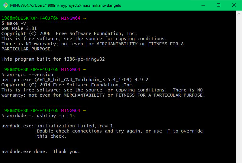
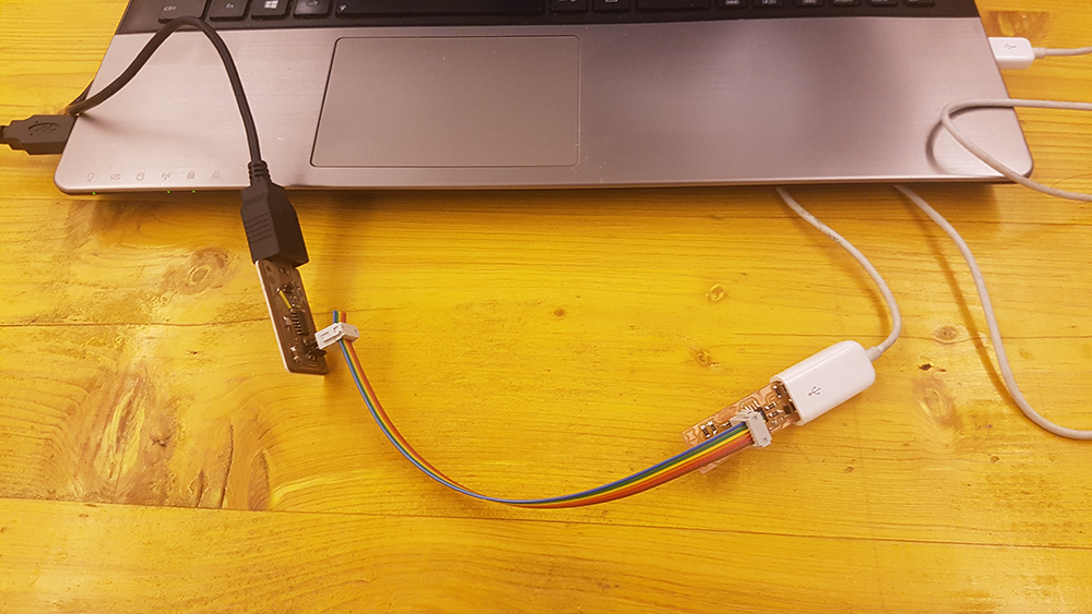
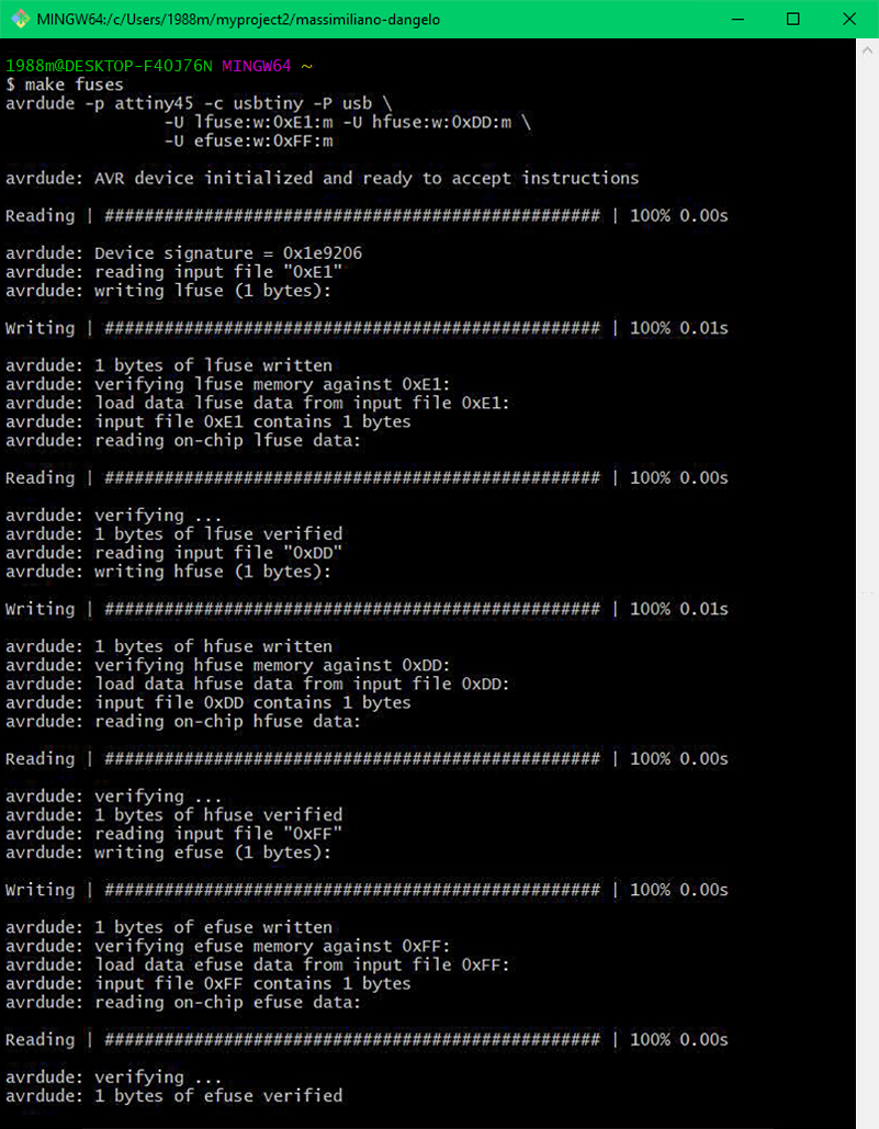
Now I've downloaded the firmware source code from Bryan tutorial page. I've extracted in a directory and from this I've launched in the command teminal Git, the command "make", to create the hex file that will get programmed onto ATtiny45. Once the command completed, I had a file called fts_firmware.hex. At this point I've used an USB extensor cable to plug my board to an USB port of my noteook, with an ISP header I've connected the programmer to my board, and with another USB cable I'v e plugged the programmer to another USB port to power it. In Git ommand terminal I've runned the command: "make flash" to erase the target chip, and program its flash memory with the contents of the .hex file. Then I've runned make fuses to set up all of the fuses, except the one that isales the reset pin.
Before transforming my board in a programmer, I tested the USB functionality. To do that, I unplugged everityng, and I plugged to USB port my board alone. I verified that it appeared in the Device Manager of Windows, and it was visible. Then I re-connected the programmer to my board and them to the USB ports again and runned the command "rstdisbl", so that the avrdude cannot communicate to the chip again through the ISP header. Now I could remove the bridge. I obtained my personal programmer!.