Exercise 05: Electronics Production
Individual assignment:
Make an in-circuit programmer by milling the PCB, then optionally trying other processes as ATtiny45 or ATiny44.
- Introduction on how to build the FabTinyISP
- PCB Fabrication
- Assembling the PCB
- Check my Work
- Software Installation
- Get and Build the Firmware
- Program the ATtiny45
- Test the USB Functionality
- Blow the Reset Fuse
- Test Your Programmer
Introduction on how to build the FabTinyISP
I followed Brian's instructions as a reference indicated in the individual assignment.
PCB Fabrication
- I downloaded the PNG files for the ATtiny45's traces and board outline:
- Traces (1000 dpi);
- Outline Cutout (1000 dpi), and converted them in .rml files, ready for being read by the Roland Modela MDX-40a mill software.
In the Fabmodules website, I first introduced the input .png image file "fts_mini_traces.png", and converted it in the output Roland Modela MDX-40a mill format "fts_mini_traces.rml", and registered the "process" as
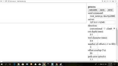
PCB traces (1/64), with the following parameters: "cut depth (mm): 0.1"; tool diameter (mm): 0.4; number of offsets: 3, then I clicked on "calculate", and I controlled the process, looking at the paths on the fts_mini_traces drawing, and "save" the .rml file, ready for the mill.
I did the same with the input .png image file "fts_mini_cut.png".I registered the "process" as PCB outline (1/32),
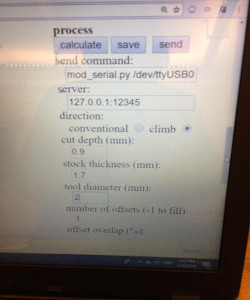
with the following parameters: "cut depth (mm): 0.9"; Stock thickness (mm) : 1,7; tool diameter (mm): 2; number of offsets: 1. Then I clicked on "calculate", and I controlled the process, looking at the paths on the fts_mini_cut drawing, and "save" the .rml file, ready for the mill.
- Fixing the Roland Modela MDX-40a for the PCB Fabrication
- Technical specifications of the Roland Modela MDX-40a
- Preparing the mill for the milling of the traces (1000 dpi) with a tool of diameter 0.4 mm
- Ready for the PCB Fabrication
- Repetition of the process for the cutting of the board
- The final object
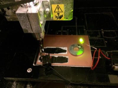
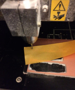
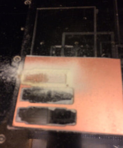
Cleaning the mill table, I fixed on it, with a double face adhesive, the copper clad board to be engraved and cut.
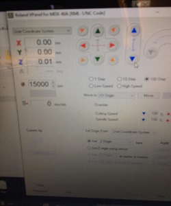
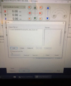
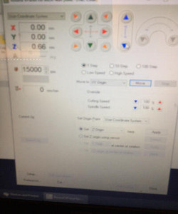
I carefully installed the cutting tool of diameter 0,4 mm. From the software, I set the X and Y axis, driving the cutting tool on the left side of the piece to be milled, and fixed the height of the tool (Z axis), thanks to an electrical contact, which indicated me with a led, when the tool touched the board. When they were all fixed, I set all axis to zero. I set the spindle rotation to 15000 rpm.I imported the "fts_mini_traces.rml" file. I shut the door of the mill. The tool was ready to start
Here some pictures:
 |
 |
 |
|---|
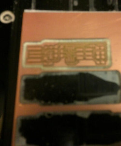
I launched the mill
Here some pictures of the process:
 |
 |
|---|
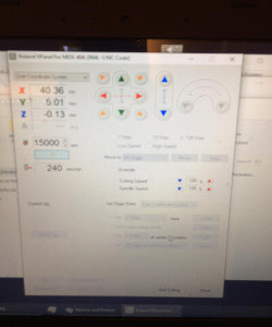
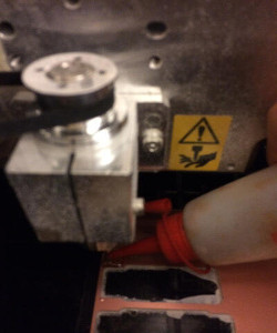
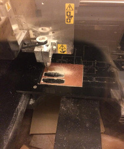
I prepared the mill with a cutting tool of diameter 2 mm, which I carefully installed. From the software, I kept the X and Y axis on zero, and fixed the height of the tool (Z axis), thanks to a piece of paper, which indicated me when the tool touched the board. I pour some oil, to stop the powder, while cutting. When the Z axis was set, I fixed it on zero. I set the spindle rotation to 15000 rpm.I imported the "fts_mini_cut.rml" file. I shut the door of the mill. The tool was ready to start
Here some pictures:
 |
 |
 |
|---|
 |
 |
 |
|---|
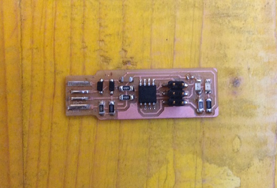
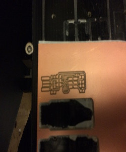
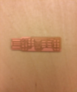
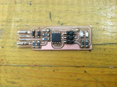
A success, ready to become an in-circuit programmer!
Assembling the PCB
I followed the FabAcademy Tutorial's instructions on how to build a FabTiny45ISP with a milled PCB.
I started to collect the components:
- 1x ATtiny45
- 2x 1kΩ resistors
- 2x 499Ω resistors
- 2x 49Ω resistors
- 2x 3.3v zener diodes
- 1x red LED
- 1x green LED
- 1x 100nF capacitor
- 1x 2x3 pin header.
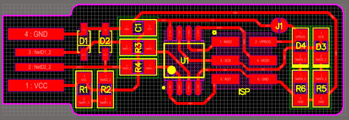
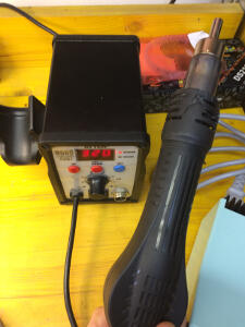
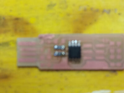
I soldered the parts to the PCB, using the schematic and board image indicated in the tutorial as a reference for component values and placement. I start with the ATtiny45 first, using Edsyn CR44 No-Clean SMD Solder Paste and a stencil. Then I fixed the ATtiny45 on the paste, and used the ATTEN 8586 solder station fixed on temperature 320°C to warm the paste. Writing this page, I read that a temperature from 183 to 260°C was enough. When the paste became brilliant, I stopped.
Here some pictures:
 |
 |
 |
|---|
Then I fixed with the same paste, the 2x 49Ω resistors, and I checked the power with a digital multimeter
 |
 |
|---|
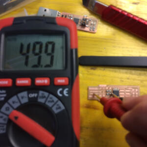
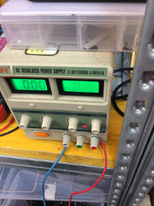
Further, I completed with the 2x 1kΩ resistors, 2x 499Ω resistors, 1x 100nF capacitor. I added the 2x 3.3v zener diodes with 1x red LED and 1x green LED: the red LED lights when the target circuit is powered, and the green LED lights when the programmer is talking to the target.So, while fixing them, I checked the light, the cathode part and the anode part of the diodes with a DC regulated power supply on 0,20 volts.
Here the pictures
 |
 |
 |
|---|
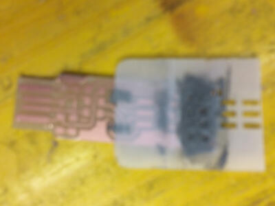
I finished to install the pieces with the 2x3 pin header, still with the paste and the stencil I ended the work with the USB contacts made with a thread of iron melt by a soldering iron hotted at 330°C.
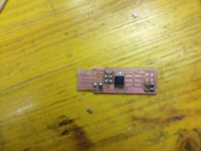
The final object
Now it is time to check my work
Check my work
Following the tutorial Week 4: Building the FabTinyISP,- I checked my board against the schematic and PCB layout image to make sure that I have installed the correct components in the correct locations and orientations;
- Inspect my board visually. I understood that components should be flat on the board, not tilted with pins in the air. Mine are not all flat on the board, but they are not tilted with pins in the air. Solder connections should be smooth, and solder should have flowed both onto the pin and onto the pad. I saw a lot of iron on the USB contacts. So, I melt the thread of iron with a soldering iron hotted at 330°C.
- Use a multimeter to check for shorts between VCC and GND. All was fine.
Software Installation
Following the above tutorial, I understood that "before I can build and program the firmware onto my board, I need to set up my development environment. I'll use this setup for all of my AVR programming for the class. The setup differs a bit for each platform, but once the software is installed it should work more or less the same on each platform. Good news! I'll be using a command line shell (bash) in my platform's terminal to execute all of the commands below." I also understood that "installing the toolchain on Windows is slightly more complicated". I followed the provided separate instructions. I am thankful to Brian Mayton, and my colleagues of the Fab Academy, Opendot.
I followed the table of contents procedure.
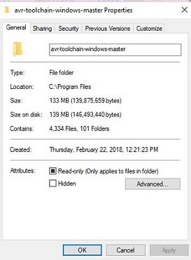
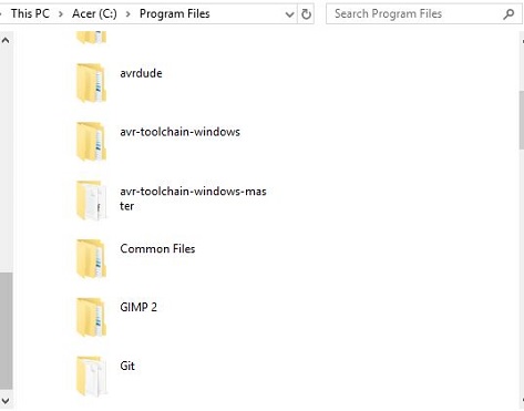
I had already installed Git for building my personal site in Exercise 02. I installed the avr toolchain for Windows of an other origin. The link to the one indicated is broken. A colleague gave me an other file. Then I installed GNU Make and avrdude.
 |
 |
|---|
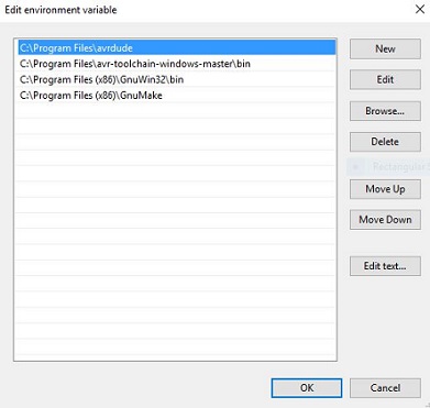
Then, I updated my Path. I told Windows where to locate all of the tools I had installed when I type their names on the command line. I went to the Start menu and opened the Control Panel, then I went to System. From the left pane, I chose "Advanced System Settings". Under the Advanced tab, I clicked the "Environment Variables" button.
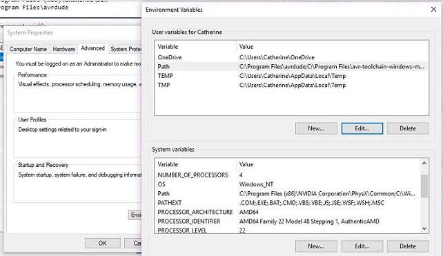
- C:\Program Files\avr-toolchain-windows-master\bin
- C:\Program Files (x86)\GnuWin32\bin
- C:\Program Files\avrdude
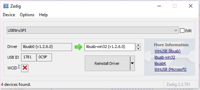
Then I installed the drivers for my Programmer The USBtiny programmers use a generic libusb driver, but Windows 10's driver signing policy makes the installation more complicated. Fortunately, there's a tool that helps with this. I downloaded Zadig and launch it. I pluged in my programmer,
and select the USBtinySPI device in the list. (If it doesn't show up, go to the Options menu and click "List All Devices". The driver I wanted to install (to the right of the green arrow) is either libusb-win32 or libusb0. I clicked the "Install Driver" button.
Sanity Check
Everything was now installed. I checked that it all works.
I went to the start menu and search for Git Bash and start it.
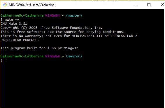
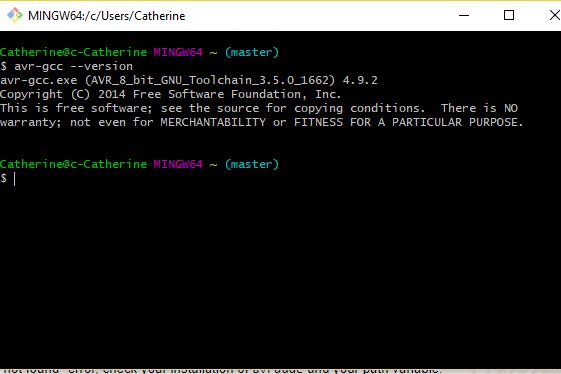
I check to make sure that the commands I installed work okay.
Here the pictures of my checking:
 |
 |
 |
|---|
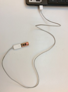
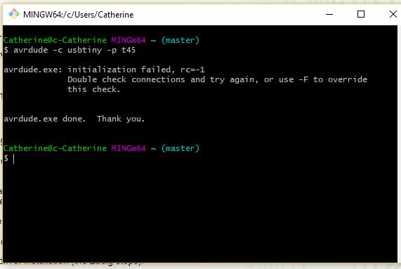
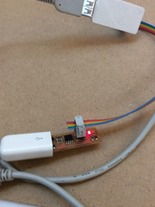
For the checking of the avrdude command, I connected my programmer to a USB port through a short USB extension cable, as in the above picture, and typed: avrdude -c usbtiny -p t45 and pressed enter. I was happy to read:
avrdude.exe: initialization failed, rc=-1
...
I understood, thanks to the tutorial, that this means that avrdude successfully found my programmer, but failed to talk to a target board (expected because nothing was connected to the programmer right now.)
YAY! I am ready to go!
Get and build the firmware
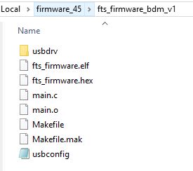
I downloaded the firmware source code and extracted the zip file. I opened my terminal program and cd .. into the source code directory.
I ran make. This built the hex file that will get programmed onto the ATtiny45. When the command completed, I had a file called fts_firmware.hex.
Program the ATtiny45
First, I checked the Makefile for the type of programmer I was going to use to program my board. The Makefile, by default, assumes that I am going to use a programmer in the usbtiny family (e.g. another FabISP board). Mine is one of the fabbed boards with an ATtiny on it: usbtiny.
Near the top of the file, I found the line that says:
PROGRAMMER ?= usbtiny: the programmer, I am using.
I plug the board into a short USB extension cable USB port, which I plug in a USB port on my computer.
The red LED installed on my board lit up.
I connected the programmer to the ISP header on my board. While connecting the cable, I understood that it is important that I get pin 1 in the right place. Pin 1 is marked in the board diagram with a dot and has the MISO signal connected to it. I looked at the plastic connector on the programmer cable for the pin 1 marker.
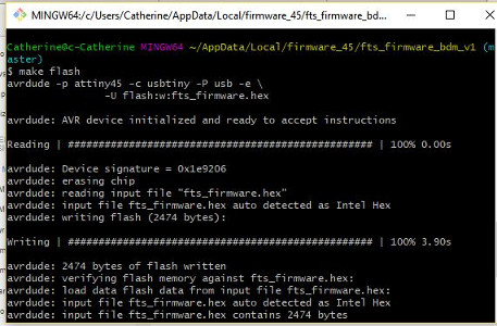
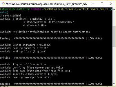
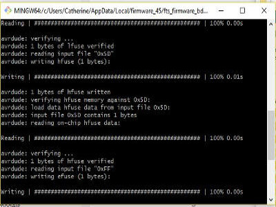
I ran make flash, for erasing the target chip, and program its flash memory with the contents of the .hex file I built before. I saw several progress bars while avrdude erased, programmed, and verified the chip.
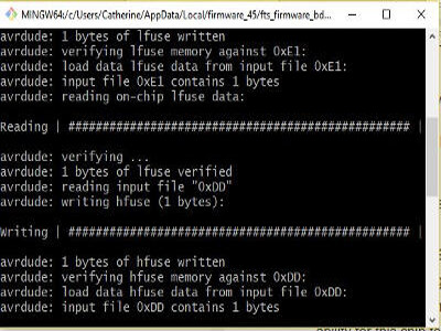
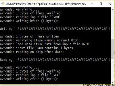
Once I had succesfully programmed the flash memory, it was time to set the configuration fuses. Following the cited tutorial, I did this in stages: First, I set the fuses that control where the microcontroller gets its clock source from. This allowed me to check that the board works as a USB device, but it won't yet be able to program other boards. Only after confirming that USB works, I set the fuse that disables the reset pin and turns it into a regular GPIO pin. This will let the chip use the reset pin to program other boards, but will disable the ability for this chip to be programmed again. Because this is not easily reversible, I wanted to make sure that everything else works first! I ran the make fuses command.
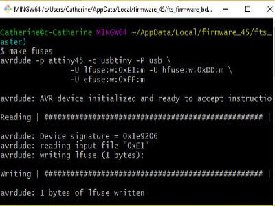
This set up all of the fuses except the one that disables the reset pin. I saw several progress bars from avrdude.
 |
 |
 |
|---|
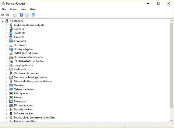
Test the USB Functionality
I checked to make sure that the USB on my board worked, before blowing the fuse that will enable it as a programmer. I unplug my board from the USB port and disconnected the programmer, then plug it back into the USB. I made sure that the programmer I used to program my board was also disconnected from the computer. My operating system is Windows Windows lists USB devices in Device Manager (Start → Control Panel → System → Device Manager), where my USBtiny device was showing up. It ws for me a success. I was happy and encouraged to go forward in the course. I looked at a colleague, and clapped his right hand. It took me such a long time to achieve this goal.
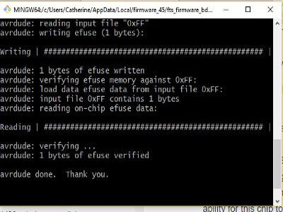
Blow the Reset Fuse
I understood that the ATtiny45 on the board has the code loaded onto it and is working correctly if I've made it this far. There are two final steps left to turn my board into a programmer that can program other boards.
At first, I needed to change the bit that will turn the ATtiny45's reset pin into a GPIO pin. Once again, this will disable my ability to reprogram this ATtiny45 in the future, which is why I wanted to make sure everything was working before doing this. I connect my ISP programmer to my board one more time, and run make rstdisbl. This does the same thing as the make fuses command, but this time it's going to include that reset disable bit as well. I saw some progress bars, and with that, I understood that avrdude will never be able to talk to this chip again through the ISP header.
 |
 |
|---|
Then, I needed to disconnect VCC from the Vprog pin on the ISP header by removing the bridge on the solder jumper. I hotted the soldering iron at 330°C, removed the solder from the jumper, thus breaking the connection.
Test Your Programmer
I should now have my very own working ISP programmer! But, before I call it a day, I'll use my board to try programming another board like the echo hello-world board in Exercise 07.