Mechanical Design
Table of contents
Introduction
Our design for a machine that makes is one that will ice a message onto a cake. This design was based on a similar machine that used a paint brush and an X axis and Y axis stage to create a machine that painted. See also http://archive.monograph.io/james/how-to-make-almost-anything. My role in this group project was to assemble the electronics and deal with the firmware. This page describes the electronics while the firmware and operation are detailed in the machine design assignment.
The finished group project for Machine design can be viewed here.
Fabnet
The interface that connects the controlling computer to the Gestalt nodes is a USB to RS485 cable from FTDI, part number USB-RS485-WE-1800-BT. Fabnet is a break out
board that allows this interface to connect to the Gestalt nodes and also connects an external power supply to these nodes, providing the power for the stepper motors.
The pcb file for Fab net was downloaded from http://fabacademy.org/archives/2015/doc/MachineMakingNotes.html
There was no board outline with this board so I created one in Eagle and then used the Modela MDX-20 to mill out the pcb. CAD files for the board and outline are available in the download section of
this page. Once the board was milled, a 2x5 way and 2x2 wway header was soldered to the pcb along with 600 ohm pull up and pull down resistors. The FTDI cable conections were also soldered to the board.

Connecting it together
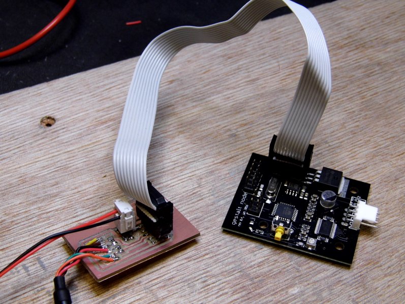
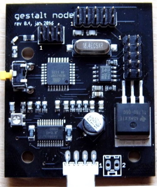
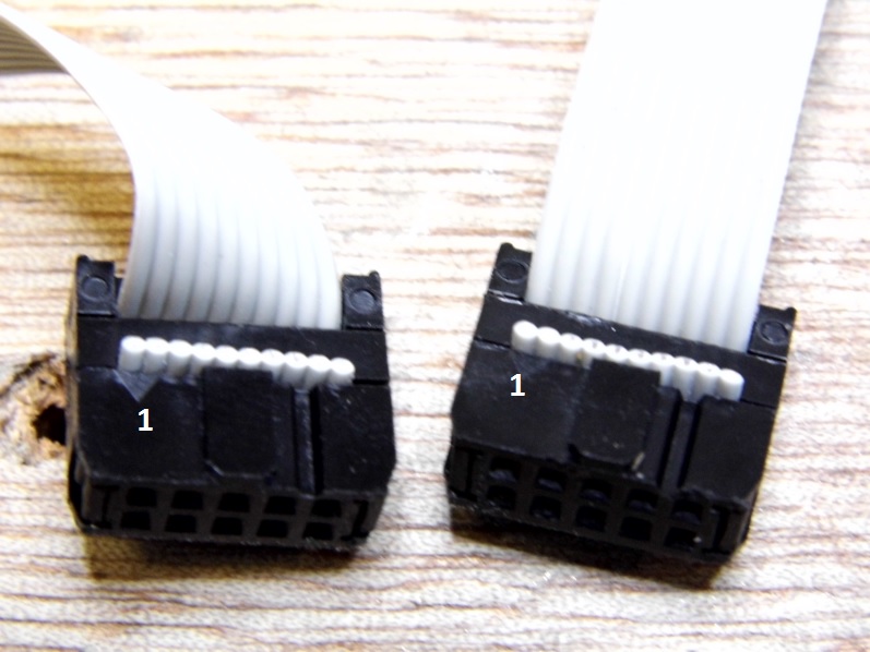
An external power supply connects to the 2x2 way header while the 2x5 way is used to connect this power supply and RS485 signals from the FTDI cable to the Gestalt nodes. A set of cables for the 2 x 5 way was made up for this. It is important that care is taken to connect the cables correcly as it is very easy to plug them in the wrong way. The images below show the Fabnet/power supply/Gestalt node connections. Pin number for the Gestalt nodes - pin 1 on the Gestalt board should connect to pin 1 on the Fabnet board. The 2x3way header is used to program the Gestalt node.
Power supply
There appears to be some confusion regarding the power supply voltage that connects to the Fabnet board and then on to the Gestalt electronics. The schematics for the Gestalt board indicate it is 24V while archive MTM builds say it is 12V. On the Gestalt electronics the main decoupling capacitor for the stepper motor/controller supply is rated at 16V. This means that 24V should not be used for the supply as doing so will damage this capacitor. For that reason we decided to use a 12V power supply. This will have negative consequences for how fast the stepper motors can run. Using a 24 supply would allow the steppers to move faster as the higher supply voltage allows the current to reach its torque value quicker.