3D scanning and printing
Table of contents
3D printing
Group part
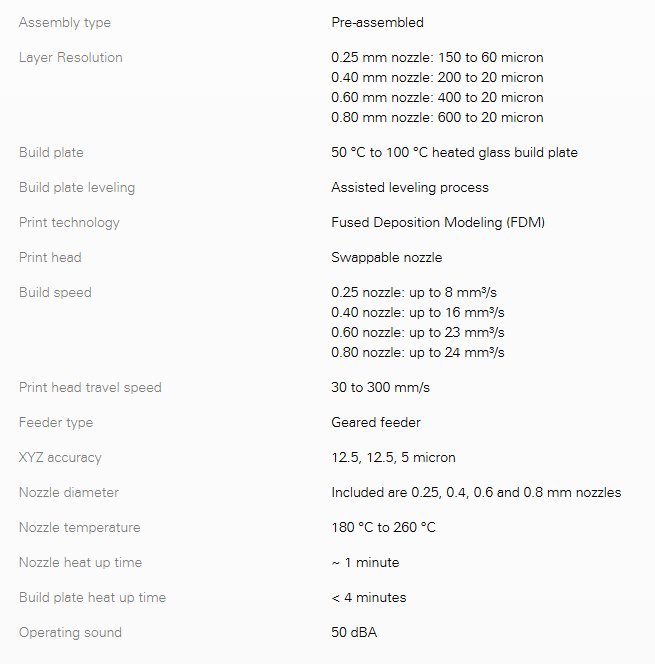
For the group part of this assignment we had to 3D print an object and then determine the quality of the printed object. For this test we used an Ultimaker 2+ which has the following specifications:
We downloaded a test print from Thingyverse and printed with green PLA filament using the standard printer settings as shown in the table.
| Printer Settings | Parameter | |
|---|---|---|
| Print temperature | 200C | |
| Buld plate temperature | 60C | |
| Nozzle Diameter | 0.4mm | |
| Layer height | 0.1mm | |
| Print speed | 50mm/s |
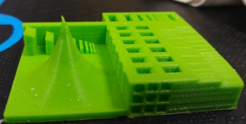
The resultant test print produced a mimimum wall thickness of 0.52 mm and the smallest gap between the walls was 0.59mm. Given the printer nozzel diameter of 0.4mm this represented good resolution, where resolution is the smallest dimensions that can be acurately acheived
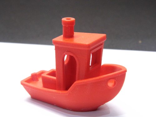
 After finsihing with the above test piece we decided to download Benchy from http://www.thingiverse.com/thing:763622 as this is a well known
test print which 'tortures' printers. Benchy you BEAST! Again this was printed on the Ultimaker 2+ using the standard print settings given above. This link
http://www.3dbenchy.com/dimensions/ gives the ideal dimensions for Benchy and you can compare them with
a Benchy produced by your own printer. When we compared dimensions between ideal Benchy and our printed Benchy the worst case accuracy was +/-0.25mm.
After finsihing with the above test piece we decided to download Benchy from http://www.thingiverse.com/thing:763622 as this is a well known
test print which 'tortures' printers. Benchy you BEAST! Again this was printed on the Ultimaker 2+ using the standard print settings given above. This link
http://www.3dbenchy.com/dimensions/ gives the ideal dimensions for Benchy and you can compare them with
a Benchy produced by your own printer. When we compared dimensions between ideal Benchy and our printed Benchy the worst case accuracy was +/-0.25mm.
Individual part
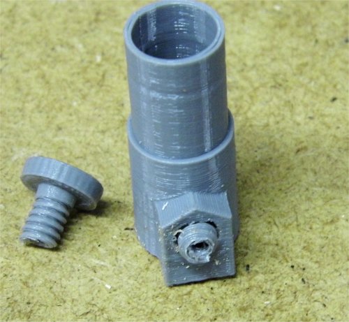
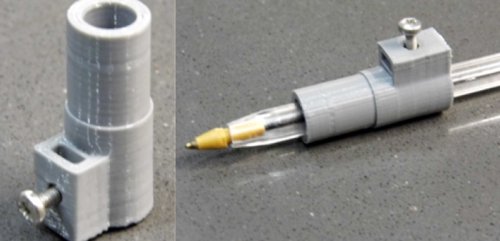
While testing the 3D printers I had printed a pen holder for the Silhouette Cameo 2 which I had downloaded from Thingyverse https://www.thingiverse.com/thing:346734. This uses a 3D printed bolt to screw into a matching threaded receptacle to clamp a pen inside the holding cylinder. When I printed this on the Ultimaker 2+ the bolt screwed into the holder perfectly but when I tried to print it on my CTC Replicator 2 the circular part of the bolt as printed on the XY plane came out as an oval shape while the matching hole in the cylinder wall printed on the XZ plane was ok. Also part of the bolt thread had melted. The picture below shows the two parts. The red part was printed by the Ultimaker 2+ and the grey part by the CTC Replicator 2.
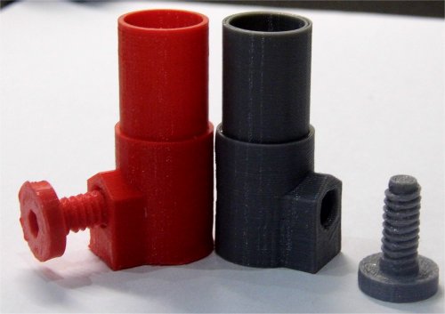
When I tried to screw the bolt into the thread I had to force it that much that the bolt snapped. Boo hoo!
Much later on I investigated this problem and found out a number of issues regarding the CTC printer which I was able to fix and get it to print as good as the Ultimaker 2+. These are listed below:
- Use ReplicatorG 0040 software to control the CTC machine as the print speed is not controlled properly or at all if using Makerware software. I was able to get far better quality prints running under ReplictorG at 40 mm/s.
- Attach a cooling duct as this allows the printed filament to cool quickly and keep the intended structure. It also prevents the extruder nozzle which is at a printer temperature of 200+ degrees C from melting the filament that has been already printed. I printed this one from https://www.thingiverse.com/thing:537918 and it makes a big difference to print quality.
- The CTC drive belts need tensioned properly. The small belt that drives the Y axis is normally loose when shipped by CTC and needs tightened. The other belts should also be tightened to matching tensions.
I discovered the above fixes later on during the Fab Academy. In the mean time I needed to produce a pen holder that my machine could print and design a part that could not be made using the subtractive process. Using SolidWorks I designed a part very like the original pen holder shown above but this time it would use a metal nut and bolt to clamp the pen in place
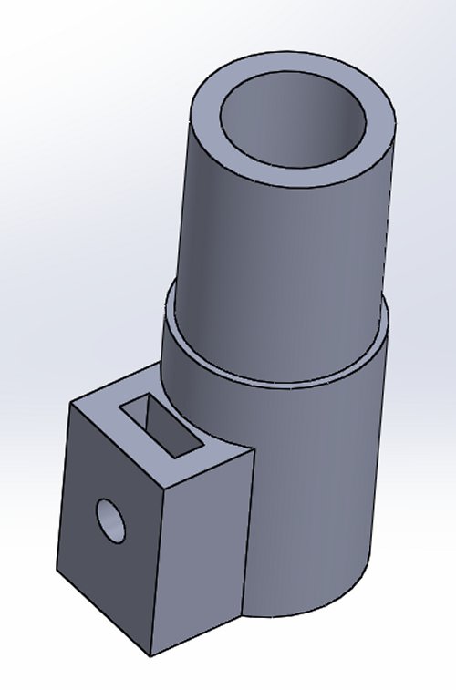
The SolidWorks part was saved as a binary stl file and printed using the Makerware software
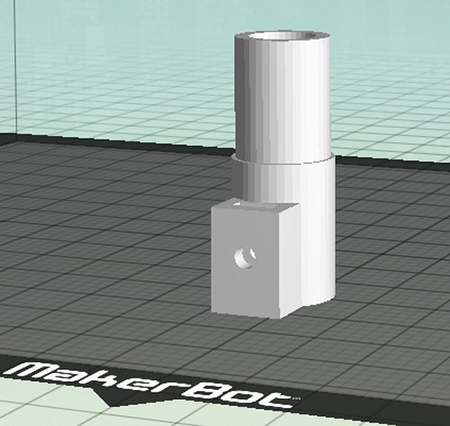
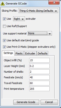
The Makerware settings to print were:
- Print temperature 200 C
- Speed while extruding 50 mm/s
- Speed while travelling 100 mm/s
- Infill = 10%
- Number of shells = 5
- Layer height = 0.2 mm
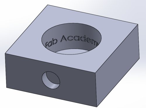
While I don't think the above file can be made using subtractive processes I decided to design another part for 3d printing that would let me test the accuracy of my printer and could only be made using an additive process. The part is a cube 50mm x 50 mm by 20 mm with a 30mm circle cut out on the top and a 10mm circle cut out on one of the sides. On the inner surface of the larger cut out I added the text Fab Academy 2017. A CNC milling machine would be unable to create this text.
I used ReplicatorG 40 as the print software with the following print settings:
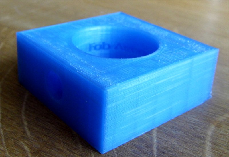
The part was printed out and the dimensions measured against the design dimensions. As measured on the X, Y and Z axis the printed part gave the following results 49.98mm x 49.6mm x 19.73mm. The large cut out as measured on the X and Y axis was 29.84mm x 29.5 mm. The small cut out was 9.83mm on the X axis and 9.7mm on the Z. These results would tend to show that there is an offset error on each of the axis which if accounted for would make the printed part very accurate.
Scanning using Modela MDX-20
The Modela MDX-20 comes with an attachment called the Roland Active Piezo Sensor and along with DrPicza software allows the Modela to scan in 3D objects.
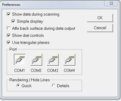
Before scanning can begin the software has to be set up to communicate with the Modela. To do this select File->Preferences and ensure the correct com port is selected. All other settings can remain the same.
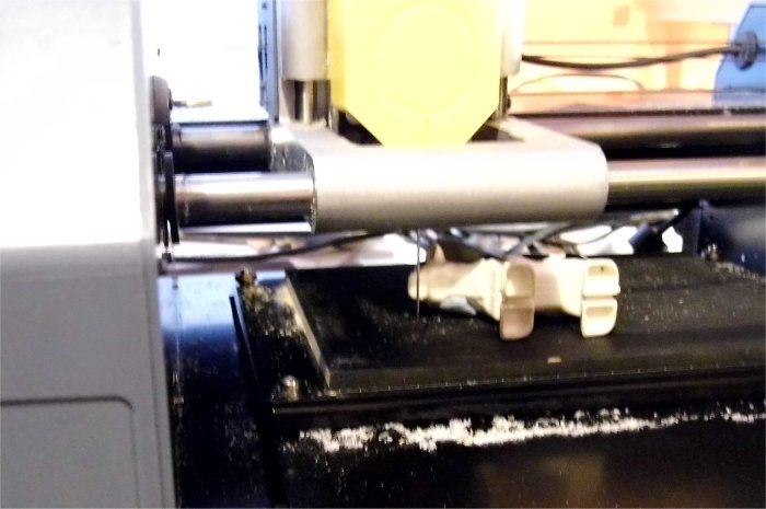
The photo below shows the MDX-20, the piezo sensor and the object to be scanned. The object needs to be firmly attached to the MDX-20 bed. For this I used Blue-Tack.

The MDX-20 scanning area is 203x152x60mm and has a resolution of 0.05mm. When scanning objects, the scan area can be reduced to match the size and position of the object. To do this, in the software menu select Control->Scanning Area and drag the small squares at the edges of the blue box to match the object's position and size. Also within the scanning area control the X and Y pitch can be set. This determines how closely together the scanned points are. The bottom of the scanning volume can be set by entering a value into the Z Bottom parameter, which determines how far in the Z direction the piezo probe will descend when scanning.

By correctly setting the scanned area and adjusting the scan pitch and Z placement the scan time and acccuracy is optimised. A useful test to check the object is within the setup scan area can be accomplished by double clicking on one of the small squares in the scanning area control which drives the piezo probe to that point and lowers the probe towards the object. If the object is outside the probe point or the probe point is too far from the object the scan area will need adjusted.
Scanning
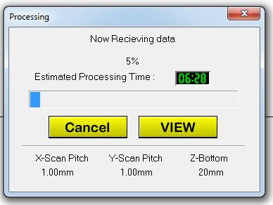
The scanning pitch was set at the defaults of 1mm for both X and Y and the Z reference was set at 20mm. This would allow the probe to scan the upper half of the object in question. Once these parameters were set the scan button was pressed and the scan started. Note it takes a long time.
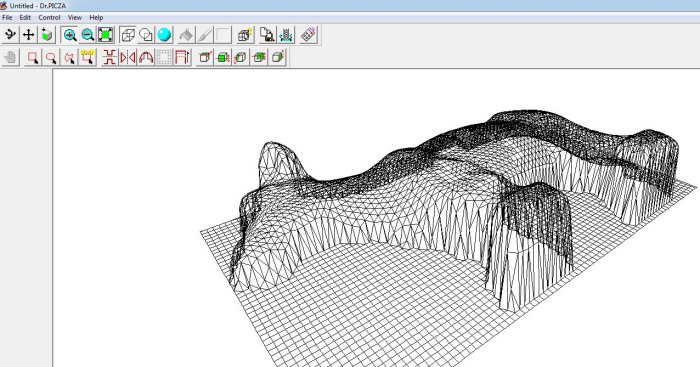
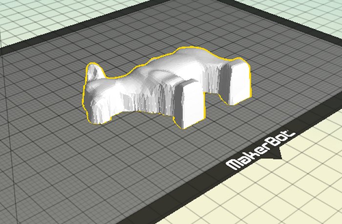
Once the scan has finished the software produces a mesh model of the scanned object which can be exported in a number of various formats. I chose stl and was able to import the scanned model into Makerbot software for printing.
Conclusion scanning
Scanning using the MDX-20 is straightforward and very accurate. It really is a 2.5D scanner but this still offers good possibilities as there are a lot of objects that are 2.5D: think of the reliefs carved on wood or moudlings.In therory a number of sides of the object could be scanned and the meshes merged to produce a more complete object. The scan time can be long and will increase if more resolution and accuracy is required but the machine can be left running in the background and is quiet so I don't see this as a problem. In short, the MDX-20 is an excellent tool for accurately scanning 2.5D objects.