Home About Projects Final Project
Martins Krebs - Fab Academy 2018

- MĀRTIŅŠ KRĒBS -

Fab Academy - 2018

Week 7: Electronics Design

Group assignment

  • Use the test equipment in your lab to observe the operation of a microcontroller circuit board.
  • Individual assignment

  • Redraw the echo hello-world board, add (at least) a button and LED (with current-limiting resistor), check the design rules, make it (if you have time this week, test it).
  • Learning outcomes:

  • Select and use software for circuit board design.
  • Demonstrate workflows used in circuit board design.
  • Have you:

  • Shown your process using words/images/screenshots.
  • Explained problems and how you fixed them, including how you worked with design rules for milling (DRC in EagleCad and KiCad)
  • Included original design files (Eagle, KiCad, Inkscape, .cad, etc.).


    Circuit Board Components


  • Resistors: As the name indicates, resistors have an electric resistance that limits the flow of the electrons through a circuit. Their role is very important in circuit designing, for example, if you connect a battery to a LED directly it will explote, you need to connect a resistor in between, usually a 1KO one. The resistance is measured in ohms Ω. And an important aspect that we have to look at is the tolerance: how accurate it is.

  • [Current(I) = Voltage (V) * Resistor (R)]


  • Capacitors: they are also a key component in almost every circuit. They store energy in a electric field and they can control voltage spikes. They can be polarized and unpolarized.

  • Capacity = Charge (Q) Voltage (V)


  • Inductor: stores energy also but in a magnetic field. Wire: allows the communication between programmer and the board.
  • Switch: this component allows you to control wether an electric circuit is open or close. They are very important for user interaction.
  • Crystal and resonators: they provide a clock signal to the circuit.
  • Diodes: their main function is to control the direction of the current flow. They are directional components.
  • Transistors: A transistor is a semiconductor component that can either amplify or switch electronic signals and electrical power. A voltage or current applied to one pair of the transistor's terminals controls the current through another pair of terminals.
  • Microcontroller: A microcontroller contains one or more CPUs (processor cores) along with memory and programmable input/output peripherals. Program memory in the form of ferroelectric RAM, NOR flash or OTP ROM is also often included on chip, as well as a small amount of RAM.
  • The main concepts that we have to know when working with circuits are Voltage(V), Current(I) and Resistence(R). Voltage: difference of potential energy betwen two points. It is measured in volts(V). Current: number of electrons that flow in a certain point of the circuit. The current flow can be defined in the conventional way or in the real way. Resistance: Is the opposition to the motion that electrons have when moving through conductors. Power: is the rate, per unit time, at which electrical energy is transferred by an electric circuit.


    Redesigning the Hello-World Board

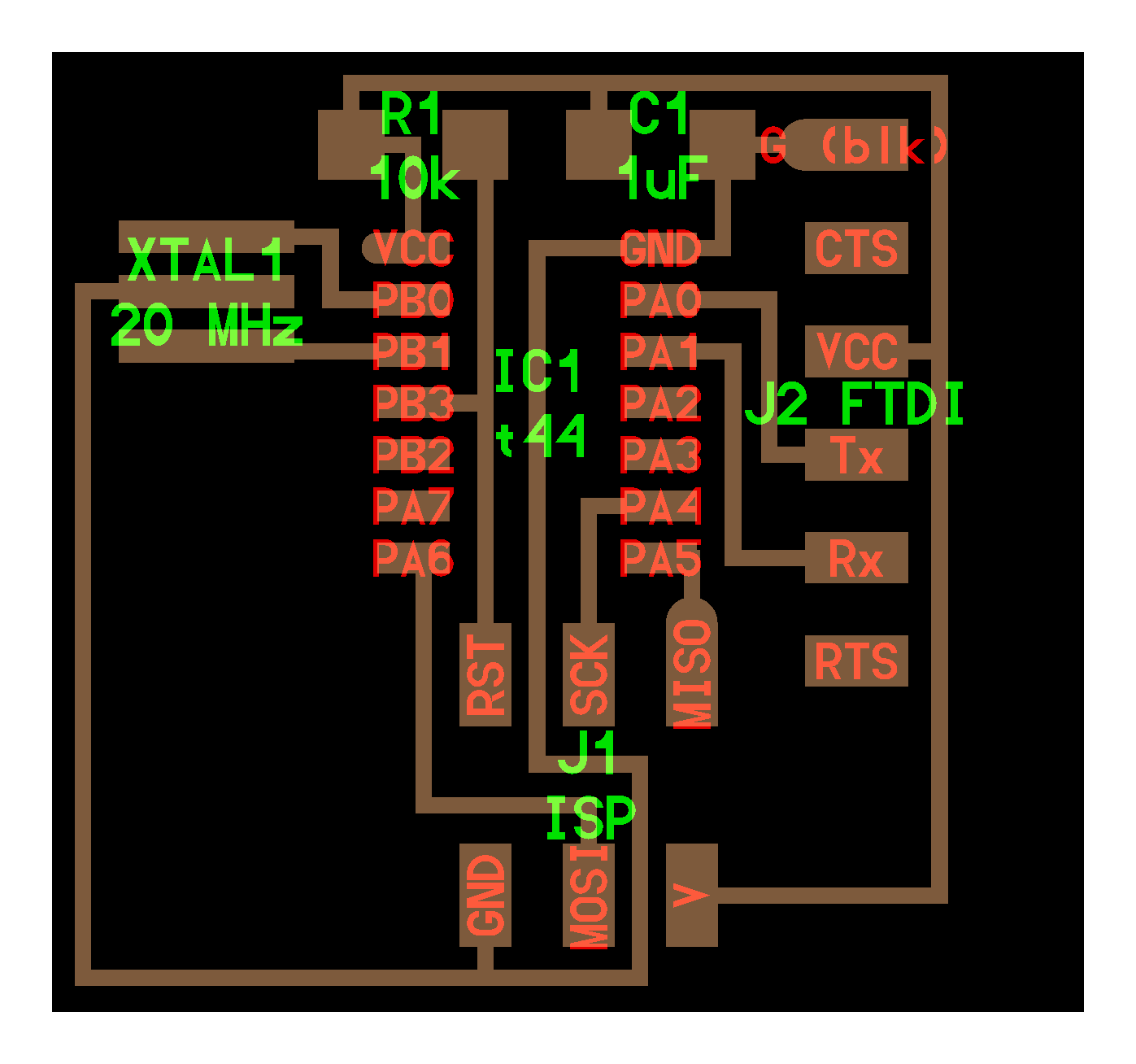
    The goal for this week asigment is to redraw the Hello-world PCB board adding some extra components like a LED and a button.

    This is the original Hello-World PCB Schematic

    The software I'm using to design the new board is called Eagle. I have the free version for students, and it has everything I need to make most boards i will need to make throughout this session

    Eagle has two main modes:

  • Schematic editor: The components are layed out in this editor without being measured precisely, this scheme just tells you how the elements are connected but this won't be the final layour in the board.
  • Board editor: this is where you distribute the components and how they will actually be oriented on the board. This is also where you draw all the traces connecting the components together and forming the correct paths to the correct ends


  • To get started on a board, we will start in the schematic view, and begin by placing all of the components we need.

    To do this, you we need to use the Add feature.


    To install the FabLab library, go to the Resources repository and download the fab.lbr. Once that is done, open Eagle, go to Options ---> Directories (this is where all the libraries are stored), and then copy/paste the fab.lbr there.


    Once I have added all my components (ATtiny44, 6 Pin heads, Resonator, Capastior, LEDs, Resistors, and a Button), We start drawing and labeling the connections and allowing the program to "connect" them when prompted.

    Drawing leads off of pins, and then labeling them, rather than drawing full connections, allows for a more easily read and cleaner schematic. (as seen above)


    After you have your schematic all drawn up and connected, switch over to the Board Editor

    Place your components inside the board space, and orient them the best you can to get all of the yellow 'leads' to be as neat as possible (it will still have a lot of interections and look somewhat messy). Begin routing the paths. I personally route all of them manually.

    After you have routed them all, and there aren't any yellow 'leads' left, It is time to


    Once your board generates without any errors, export the file as a PNG, or use the cam processor to create a Gerber file for the LPKF Mill.

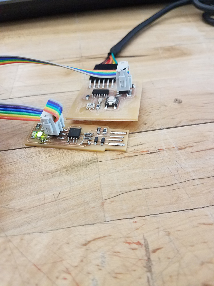
    After my board was cut, I was a little surprised at how small it came out. Once I soldered on all the components though, I liked the aesthetics of the compact board compared to other examples I saw. (I know aesthetics hardly matter here)


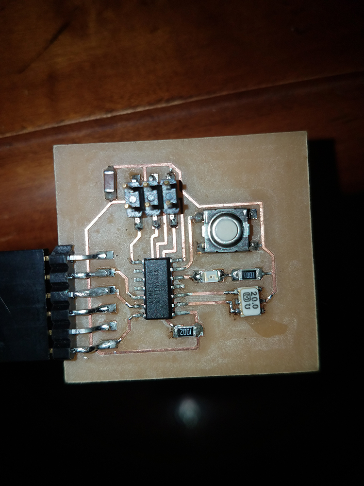
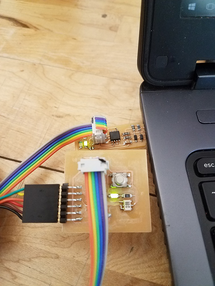
    Image testing and programming the board with my toolchain.