Today's Menu
Exercise 3
Computer aided cutting
New week, new chapter. Now it's getting serious. The goal this week is to get cutting. We've learned how to use several different machines to do a variety of tasks. Some of those tasks were a group effort, and some we did on our own.
Cutting vinyl - making stickers
This was the most straightforward part of the assignment. The First step was to receive a vector graphic of my lab's logo from my PostDoc, whose design it was originally.
![]()
The original SVG file is available here.
Hardest part of that was getting Inkscape and X-windows to work on my Mac. After a certain amount of swearing and plenty of patience, we got there in the end. Once in Inkscape, I then had to save it as a DXF file using the option shown below.
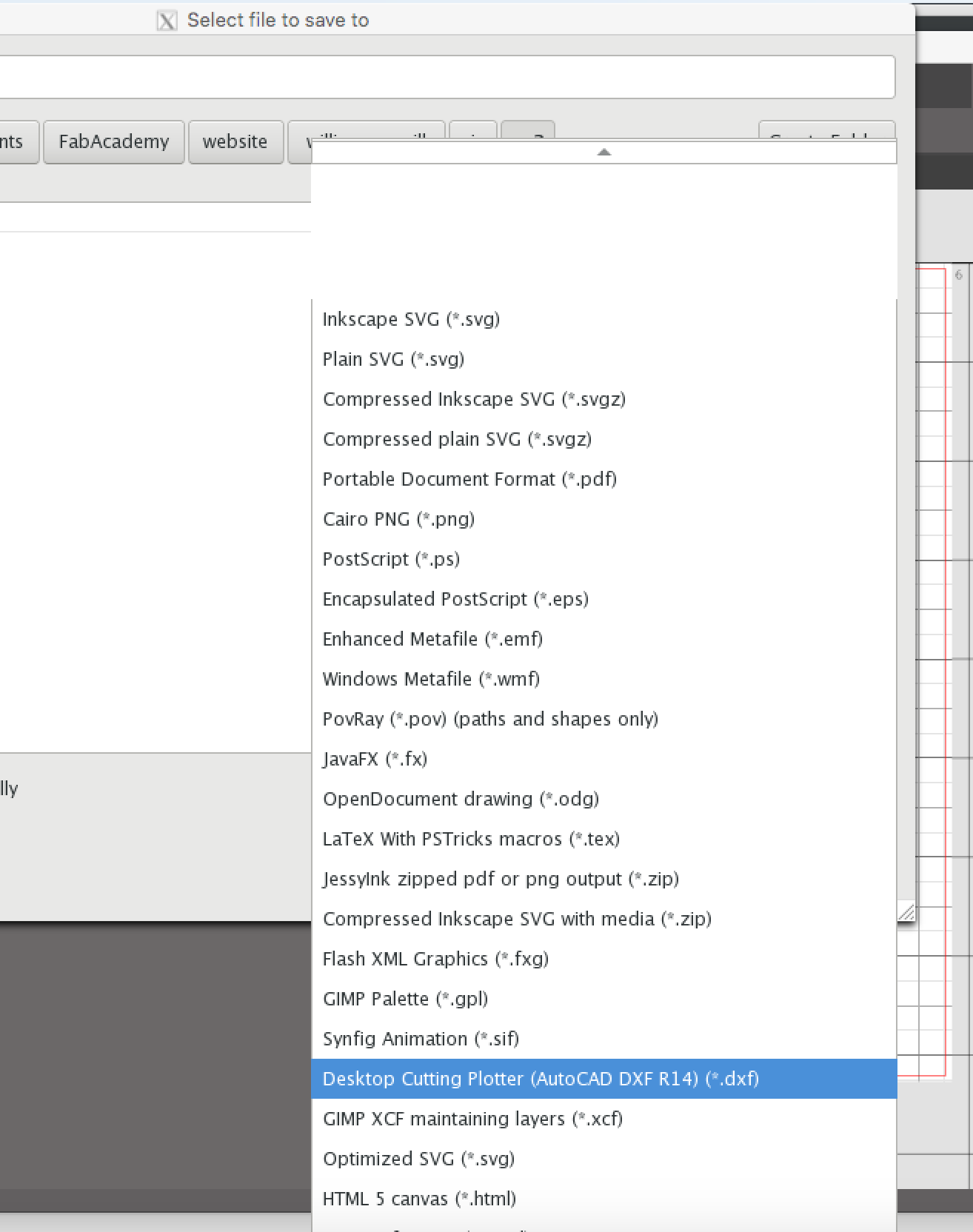
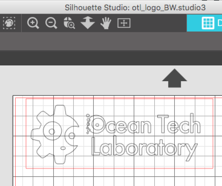
Then it had to be opened with the vinyl cutter's own "Silhouette" software, which loaded it as an outline. This was then surrounded with a rectangular box, as shown.
This was ready to be sent to the machine. A grey coloured vinyl sticker sheet was sourced and stuck to the template provided with the machine, taped in place along the edges with masking tape. The template and vinyl were then fed into the cutter. The cutter blade was tested on a small piece, and we found that it had to be set on depth "3" in order to cut completely through the sheet.
The printer was then turned loose with the file and it generated the desired pattern. On completion of the cutting, the vinyl and template were removed from the machine, and sticker was peeled off the template. First the negative was peeled back, carefully using a sewing thread cutter to hold down the delicate parts, and then the same thread cutter was used to separate the centres of letters and some of the contained parts of the logo. These were then stuck onto the lid of one of the lab's Macs.
![]()
Masking tape was then laid over the positive cutout and peeled back with all of the delicate elements intact, and used to transfer the logo to the lid of a second Mac.
The final result is gorgeous.
![]()
Engraving with a laser cutter
We did this activity as a group on the Friday after it was assigned. The assignment called for us to characterise the lab's laser cutter. We decided to prepare some sample cards with the various settings and materials to show other users what the machine can do. The first of the cards was to be the cover sheet for our little "book". We wanted to show the logo of the laser cutter and some text to demonstrate the various skills we were supposed to learn.
We started with the photo below, taken using an old iPhone. We played a lamp on the top left corner of the picture to generate some interesting shading effects we hoped would show up on the engraving later.
![]()
We did a lot of messing about in Adobe Illustrator to get the picture "just right", but unfortunately the whole thing got deleted over the weekend, and we have nothing to show for our efforts except an understanding of how the program works.
Obviously that's not an acceptable end point, so here's another go at getting it sorted, this time working from home with the tools I have immediately to hand. I imported the iPhone photo into Keynote, then adjusted the colour levels using that program's interface, as shown below.
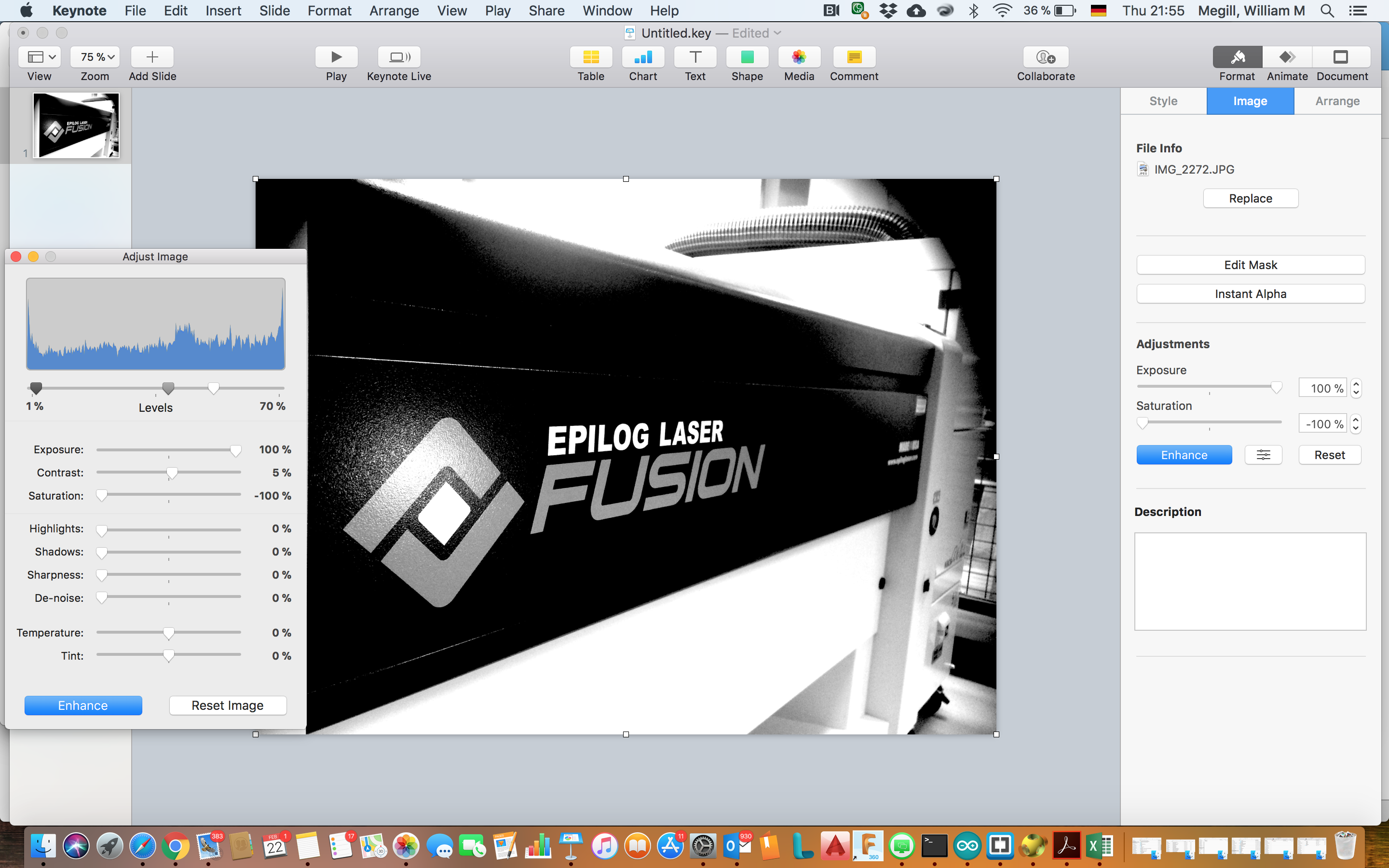
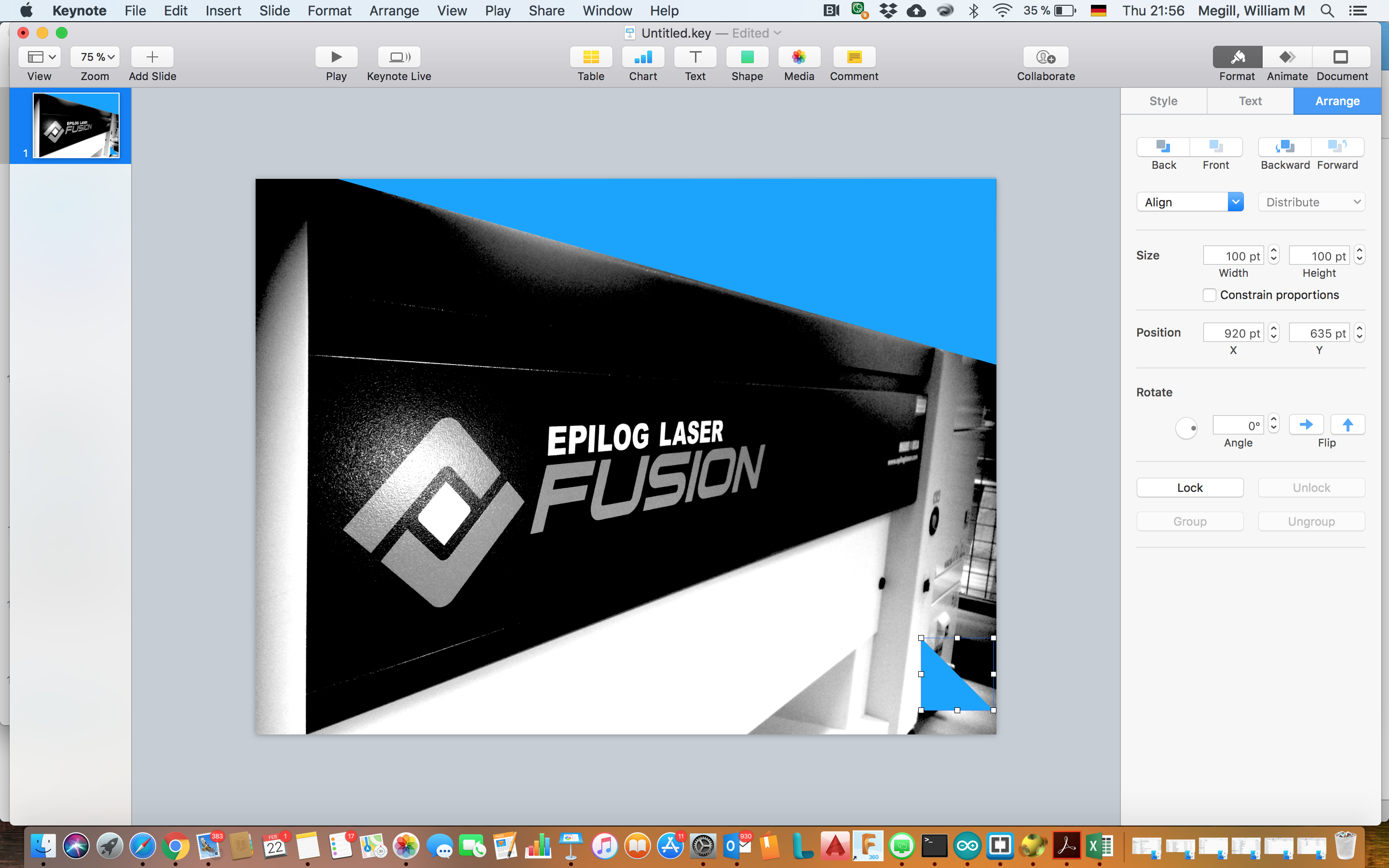
Keynote's picture editor is a fairly standard one - the same features are readily available in Illustrator, Corel PhotoPaint, Gimp, et al. After the Friday lesson in Illustrator, we learned that the best format for our book cover was going to be a high-contrast black & white image, with the logo highlighted out of the background. This was achieved by taking the saturation all the way to zero (to create a greyscale image), then by adjusting the levels to compress the colour distribution and create the very contrasted image shown. We weren't particularly interested in the background features around the blue front of the machine, so I cut those out by drawing triangles and a rectangle over them in Keynote, then filling them with white colour.
 |
The final result, now ready to be transfered to Rhino on the lasercutter computer for printing, is shown in the image below.
More soon on using Rhino to engrave MDF.
Cutting with the laser cutter
Learning to cut with the lasercutter was part of our making a cover exercise. I'll document that next time I'm in the lab.
Safety around the lasercutter is paramount. Our instructor had got sidetracked with something else while we were making our first cuts, so I casually went over and picked up the fire extinguisher from the wall. Carrying it quietly across the lab quickly got his attention!
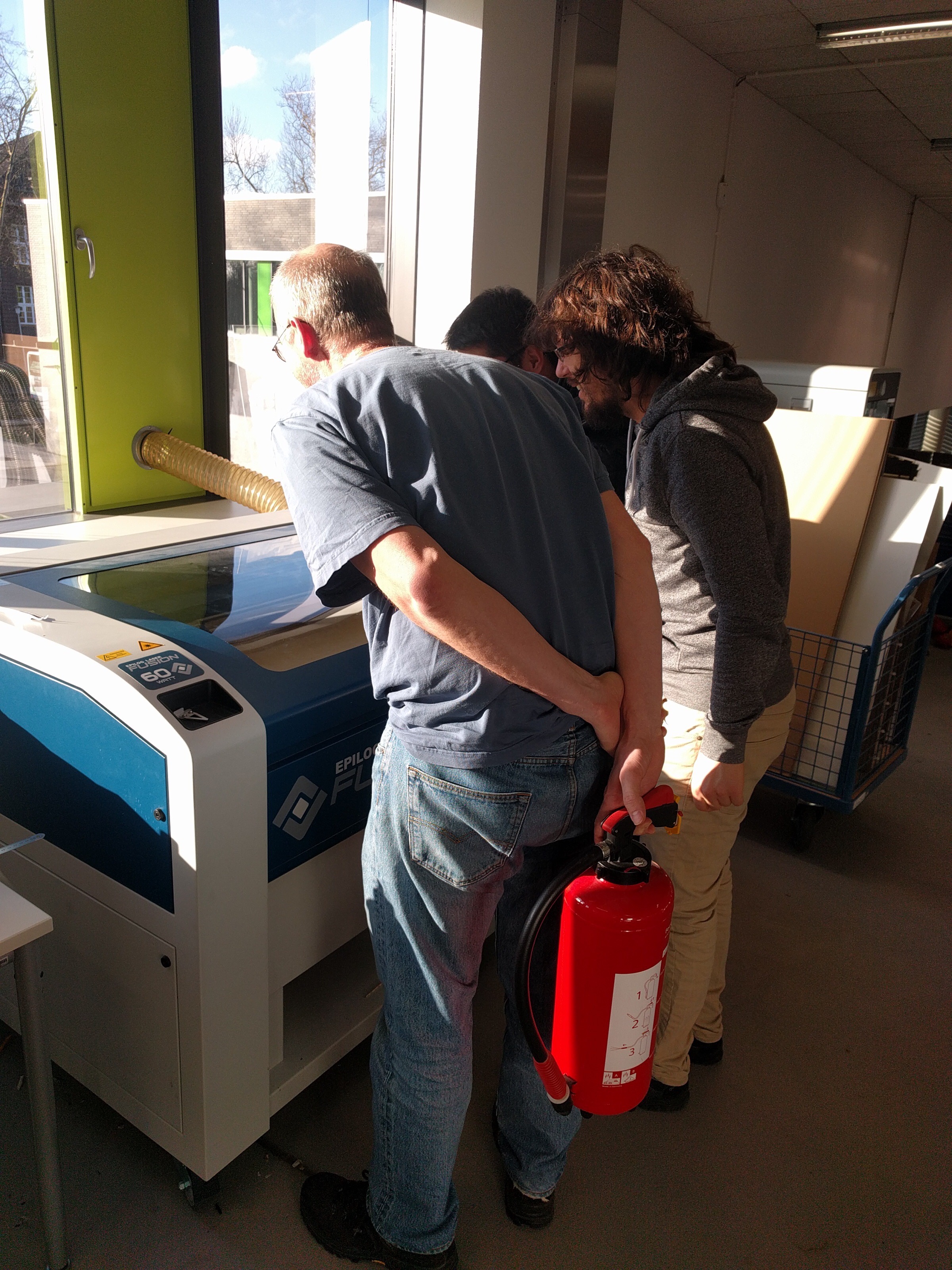
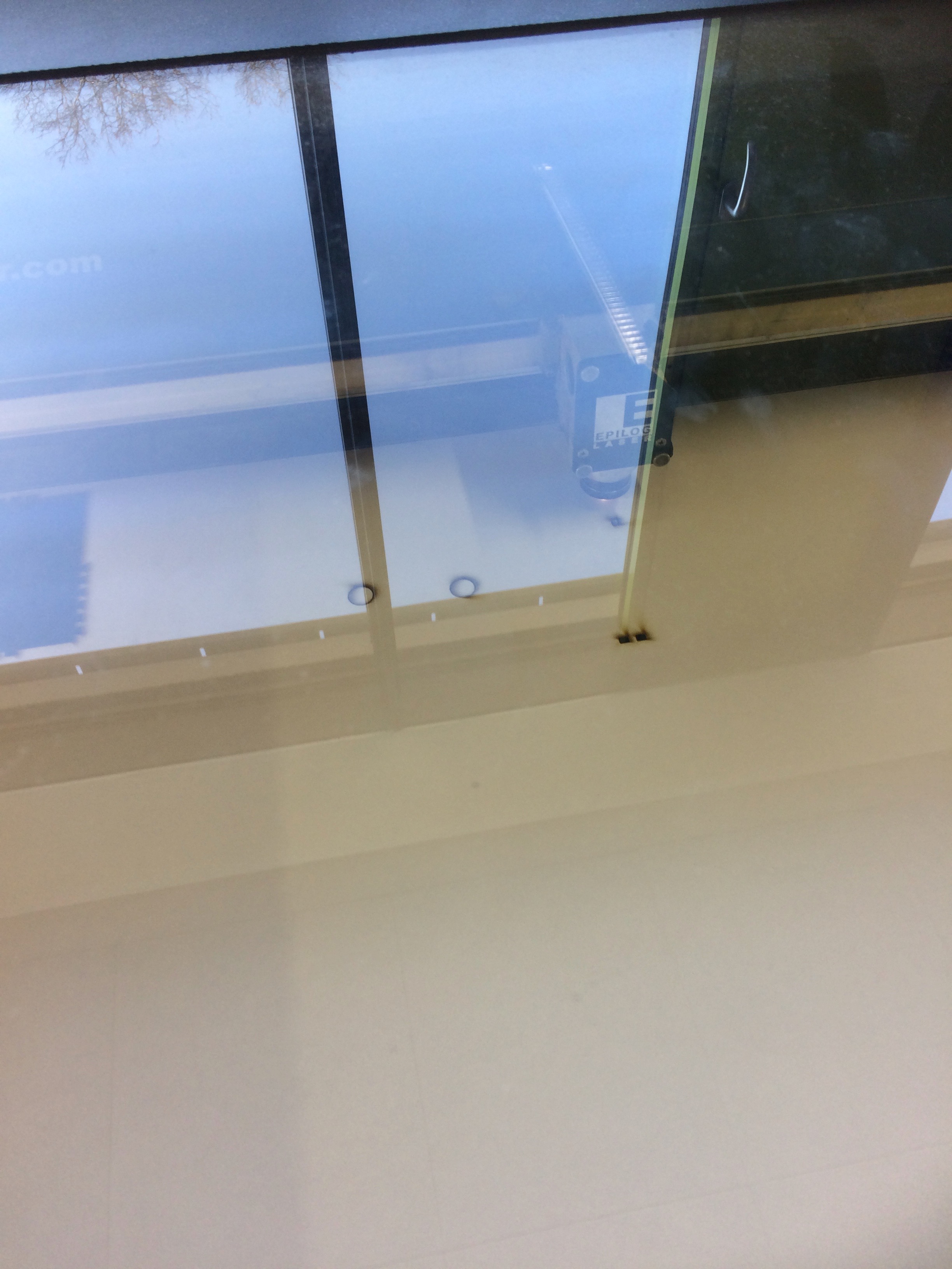
We have a 60W Epilog laser cutter. The standard operating procedure for this machine is as follows:
- Open the lid and remove any large "swarf" from the bed - think fire hazard.
- Place the material to be cut squarely against the edges. Check it's level in the bed. Use masking tape if necessary to tack it down.
- Turn on the laser cutter (switch below the emergency stop button).
- Select "focus" from the menu pad.
- Drive the bed down and away from the lens.
- Place the aluminum hanger on its studs.
- Drive the bed up until it just touches the hanger (watch for it to stop swinging).
- Centre the joystick and push it in to set the focal length. Remove the aluminum hanger.
- Select "jog" from the menu and turn on the spotter laser.
- Drive the head to the desired top-left position on the material.
- Push in the joystick to set the zero.
- Turn on the vacuum pump (button low down to the right).
- Set the menu to "job". The machine is ready for computer input.
Preparing the print job
As far as the controlling computer is concerned, the laser cutter behaves just like a printer. The trick is to prepare the job with the correct attributes so that the printer driver knows how to interpret the image.
The first step is to distinguish between raster and vector graphics. Scans covering a surface area are typically done with raster graphics, while lines are generally done with vectors. The printer driver can handle both, even in the same job, as long as the settings are appropriately entered.
I used Rhino as my primary tool to prepare the jobs for printing.
Calculating the kerf of the laser beam
My involvement in this part of the group exercise was just to draw a cartoon of the test pattern and explain the maths. Again, back to the Keynote scratchpad:
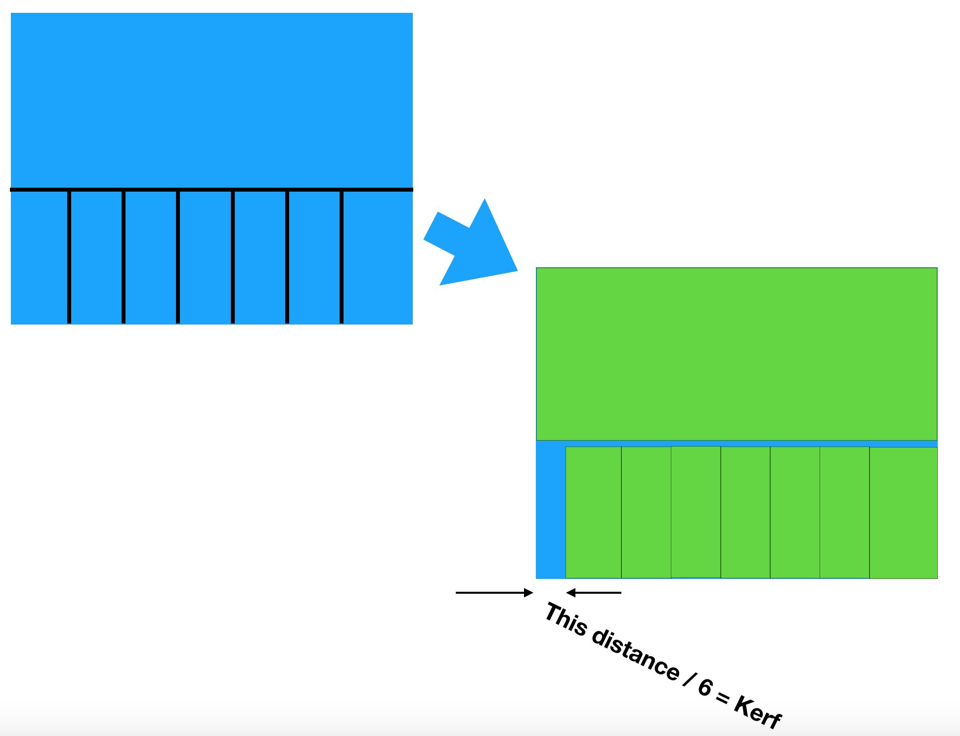
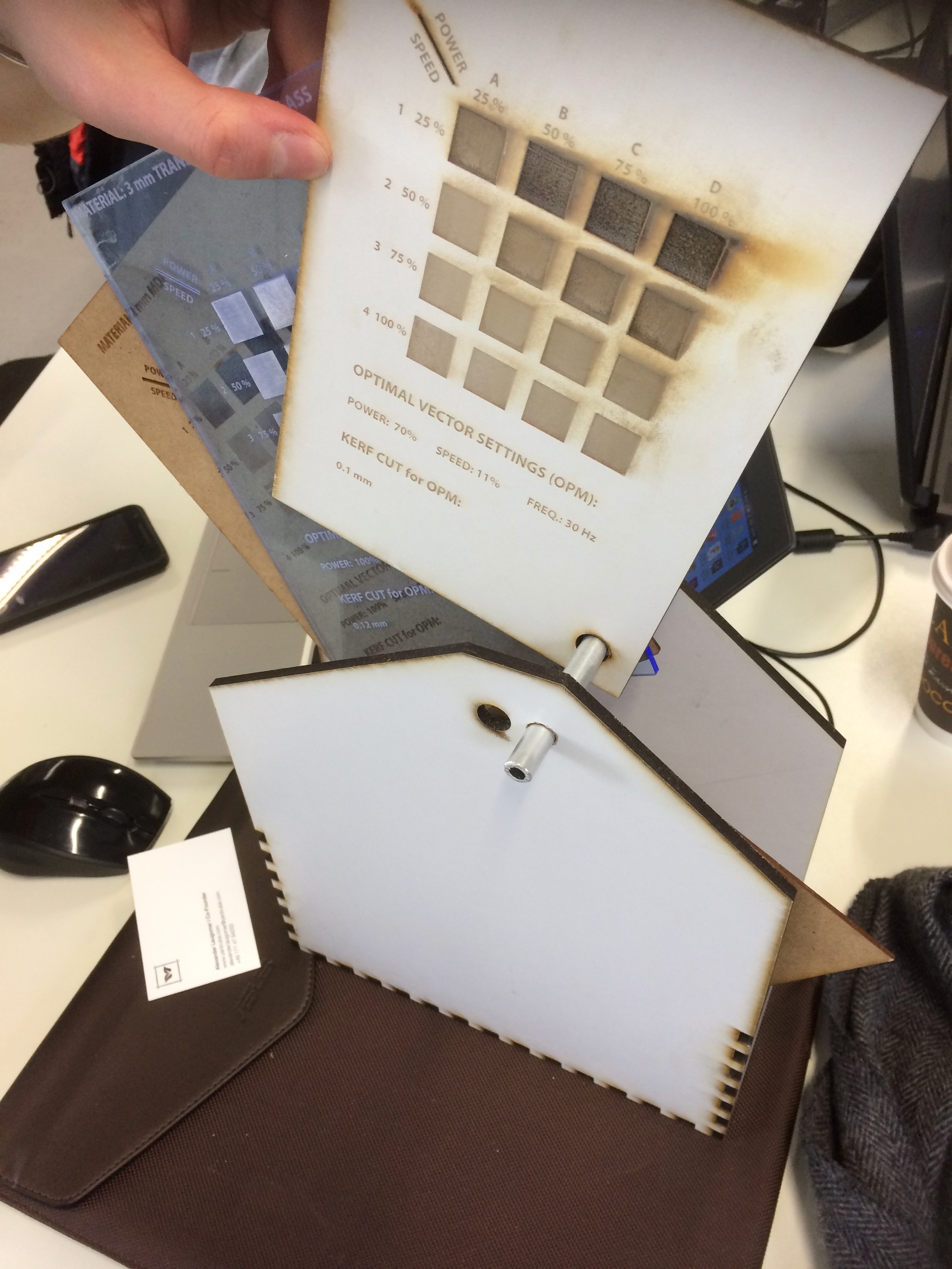
The boys did the cutting and the measuring, and determined the kerf for a 5mm MDF board to be 0.135mm. They worked out the kerf for several other thicknesses and materials, and added the results to the template pages they made to show the different settings.
Making a jigsaw puzzle
This took up most of the week. Initially the concept was to make a frame for the test cards we'd made as a group for the lasercutter. The idea was to make a sort of rolodex for the a5-sized MDF and Acrylic cards, which would be hung by their bottom right corner on a bar, then rotated out and up to a vertical position such that they could be read properly.
I started looking around for ways to combine the need for a holder for the cards with this week's requirement to develop a parametric design, and my gaze fell on the castellated boxes that dot our lab.

A first attempt: SolidWorks
I've been doing a lot of SolidWorks CAD on another project lately, so I thought I'd give it a go for this exercise. Little did I know what I was letting myself in for...
The drawing started out pretty straightforwardly. The concept was after all just a five-sided box, with a bit of fancy shaping at the open end.
The challenge came as I tried to get the castellation to work. There is a function in SolidWorks called "Linear Pattern". I'd seen people use it nicely to generate teeth on a gear, so it seemed the right tool to use. Many hours (nay, days) of frustration later, I discovered that in order to make the repeating pattern into a single closed chain, one has to also select the point at the end of the chain, and include that in the repeating pattern. Then the edge has to be cleaned up to fit the width of the design.
Later, once I thought I was set, I realised that I don't have Excel installed under Windows on my Mac, and SolidWorks can't see through the Parallels installation to find it under the MacOS. So that was the final straw. No parametric design for me in SolidWorks after all.
OpenSCAD
Having run out of time, it was back to my trusty steed. OpenSCAD uses a programming language to generate its 3D imagery. There are some idiosyncracies to the language, but as I described in the first exercise, once you get used to it, the power of the program is obvious.
To make a fully parametric design, I started by defining a program structure. Overall parameters would be followed by a section including information about the various parts. Then would come a set of "if" statements to control the display of the parts. Next modules were created to control the creation of the parts themselves. Finally a pair of modules created the castellation in x and y.
I'll describe the program in the next updates. Meantime here is what it produced. The code that produced it is down at the bottom of the page.
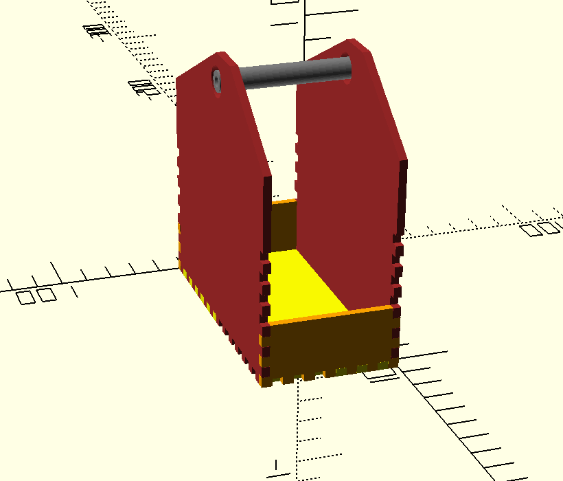
To cut the parts on the laser cutter, I commented out the "linear extrude" commands from each of the part descriptor modules, then selected one part at a time, with a rotation of [0,0,0] so that it sat flat on the x-y plane, rendered the object, and saved it as a 2D DXF file.
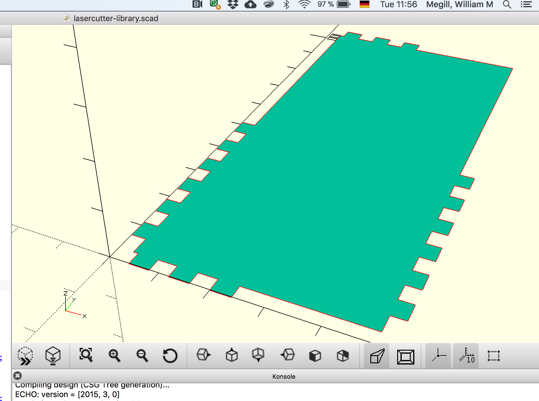
The DXF files imported quickly and easily into Rhino. From there I was able to print directly to the lasercutter using the settings the team had determined earlier in the preparation of our "book" pages.
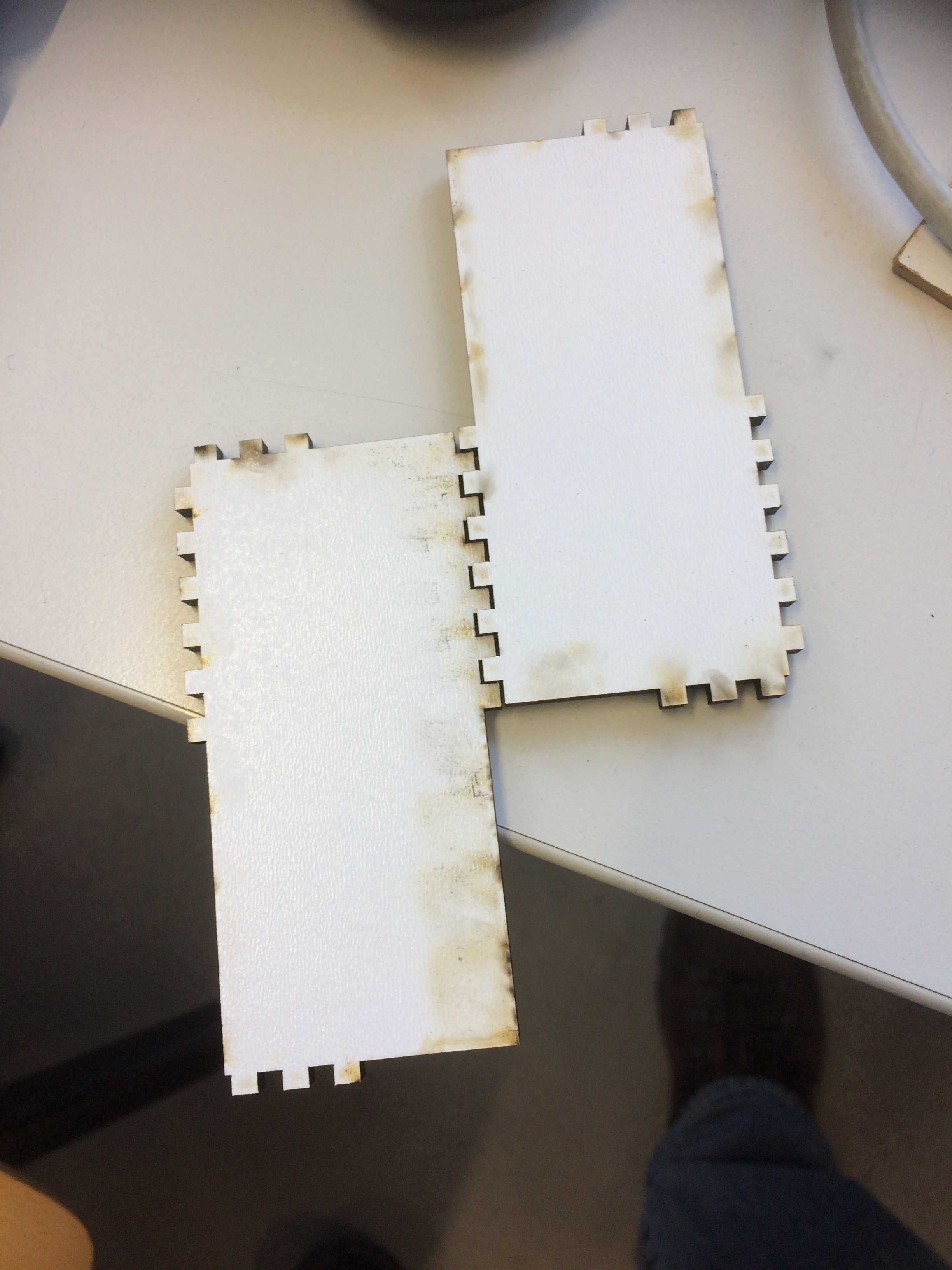
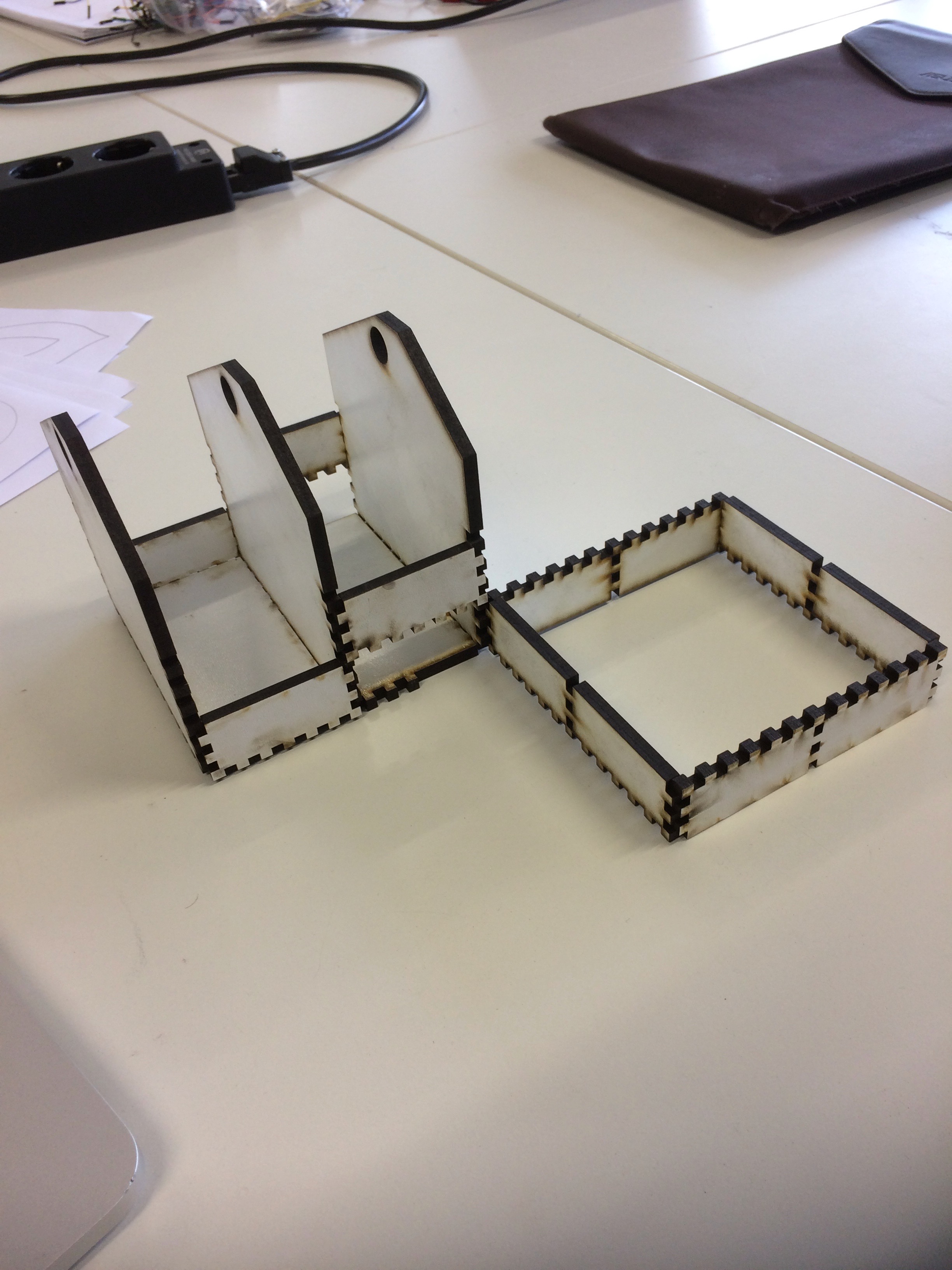
I repeated the process for the rest of the parts. It was only as I started to assemble it all that I realised that I'd goofed. In my program, I had set the code for 3mm MDF, but in selecting a bit of it from the materials cart, my mind was already in full-size gear, so I pulled out a 5mm piece. The cuts were ok for depth, but the extended bits I'd made to connect multiple units together didn't fit, as the holes in their middles were narrower than the thickness of the middle vertical wall. So instead, I made a virtue of necessity, and made them into a fenced off bit of "garden" next to my "house":
Downloads
- DXF files
- Base
- End Wall
- Back
- Front
- Long back piece (section joiner)