Contents
Molding and Casting
2. 3D CAD
3. CAM
4. Cutting
5. Casting
6. Casting
7. Result
Molding and Casting
1. Objectives
1. Objectives
Happy molding and casting week! before that we will have to review the safety data sheets for each material and prepare the 3D model CAM processing and then I am going to mill the molding and then cast a pulley gear.
2. 3D CAD

Our aim is to create a molding model, I have modeled this model in solidworks and then export them in DXF file.The material of the work piece is made out wax with a dimensions of 142 mm x 92 mm x 39 mm.
3. CAM
I used Fusion 360 CAM processor to generate the g-code for the CNC machine and in this chapter I am going to describe how to process from the stl file to the g-code.
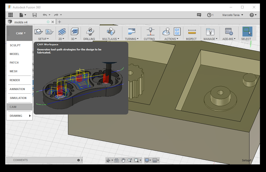
I exported the 3D CAD to Fusion 360 and then select CAM on the workspace.
3.1 Setup
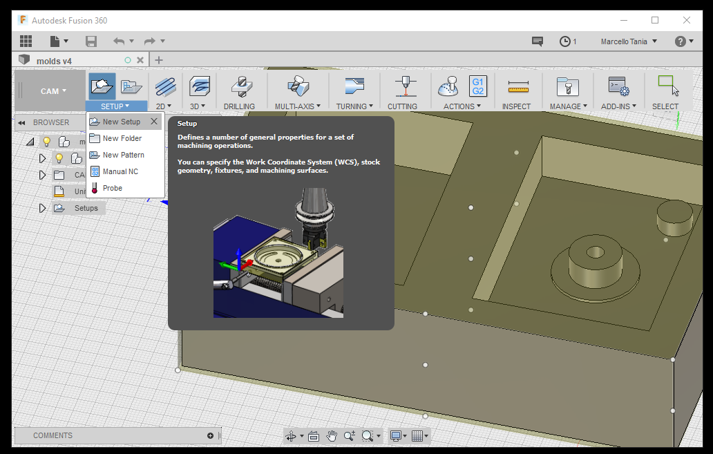
Create a new setup.
3.1.1 Setup settings
The machining type that we are going to use is milling. Set the orientaion to define the orientation of the x,y,z machining plane and the z- spindle axis.
Then specify the X,Y,Z initial coordinates where you want to set the home coordinates in the CNC.The Origin allows you to set the reference for defining part zero.

3.2 Stock
In the stcok menu, choose fixed size box to ahve a cubic stock. I wrote the dimension of the stock slighly smaller to make sure that the CAM is not cutting the edges of the stock.
3.3 Milling techniques
In my case, I decided to make two jobs: rough cut and finishing cut with the same tool.
3.3.1 Rough Cut
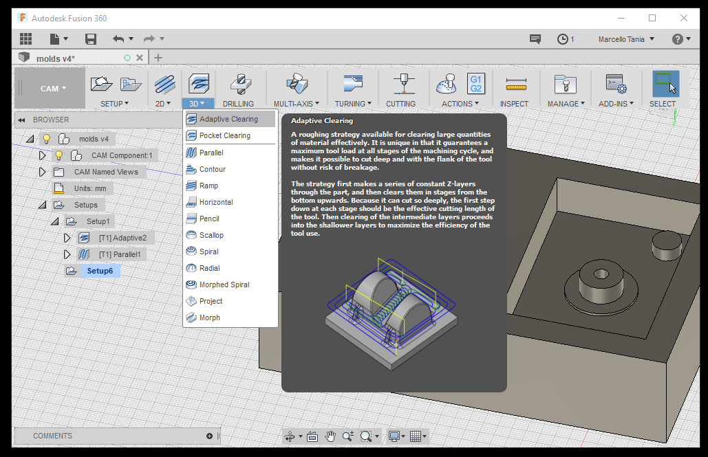
For the rough cut I choosed an Adaptive clearing because it is a good stategy to remove large quantity of material effectively
3.3.1.1 Tool

Select the tool and make sure that the tool has a good dimension to what your need for exaple the length of the tool to have a maximum cutting depth and the diameter of the tool to drill a hole.In case that you do not have a tool properties in the library, simple add the tool

Add a new tool or edit it.
3.3.1.2 Tool Properties
This is the deminsion of the tool from the data sheet.

There are two options to fill the dimension of the cutter, we can measure it manually or take a look the data shit of the drill so I put the dimensions on the Fusion 360 and then double check by measuring the tool with vernier caliper.
To determine the bodylenght of the tool, we have to meausure it afer the tool is inserting to the milling machine.
3.3.1.3 Feed and Speed
More or less I keep the option as recommended.
3.3.1.4 passes
After choosing the tool fill the parameters, spindle speed and the cutting feedrate for the feed and speed. Make the tolarance as you would like to and the maximum roughing step, I choose 0.5 mm tolarance because this is just rough cut and you do not need to be more precise efficiently.
Incrase the optmal load to 1 mm to decrease the machining time in the rough cut.
3.3.1.5 Simulation
Press ok after filling all the properties that is required to fill in and then the software will simulate to depect if the machine is not colliding.In the simulation you could take alook that the blue line is removing the material, yellow represent jumps and red is plunging.

In the simulation you can see the amount of the collision and make sure that there is no colision.
3.3.2 Finish Cut

Parallel is widely used for finishing.
3.3.2.1 Tool
I choose the same tool but normally, it is better to use a smaller diamter of the tool to give a better surface finish.
3.3.2.2 Feed and Speed
3.3.2.2 Passes
In the finish cut it to make a very accurate result and the rough cut is to remove the material as fast as possible.Therfore decreased the tolerance into 0.01 to have better finish surface.The only thing hat I change is stepover to be 0.5 because I want it have smooth surface in the finish cutting.
3.3.2.3 Simulation
In the simulation again make sure to not have any collision.
3.4 Post Process
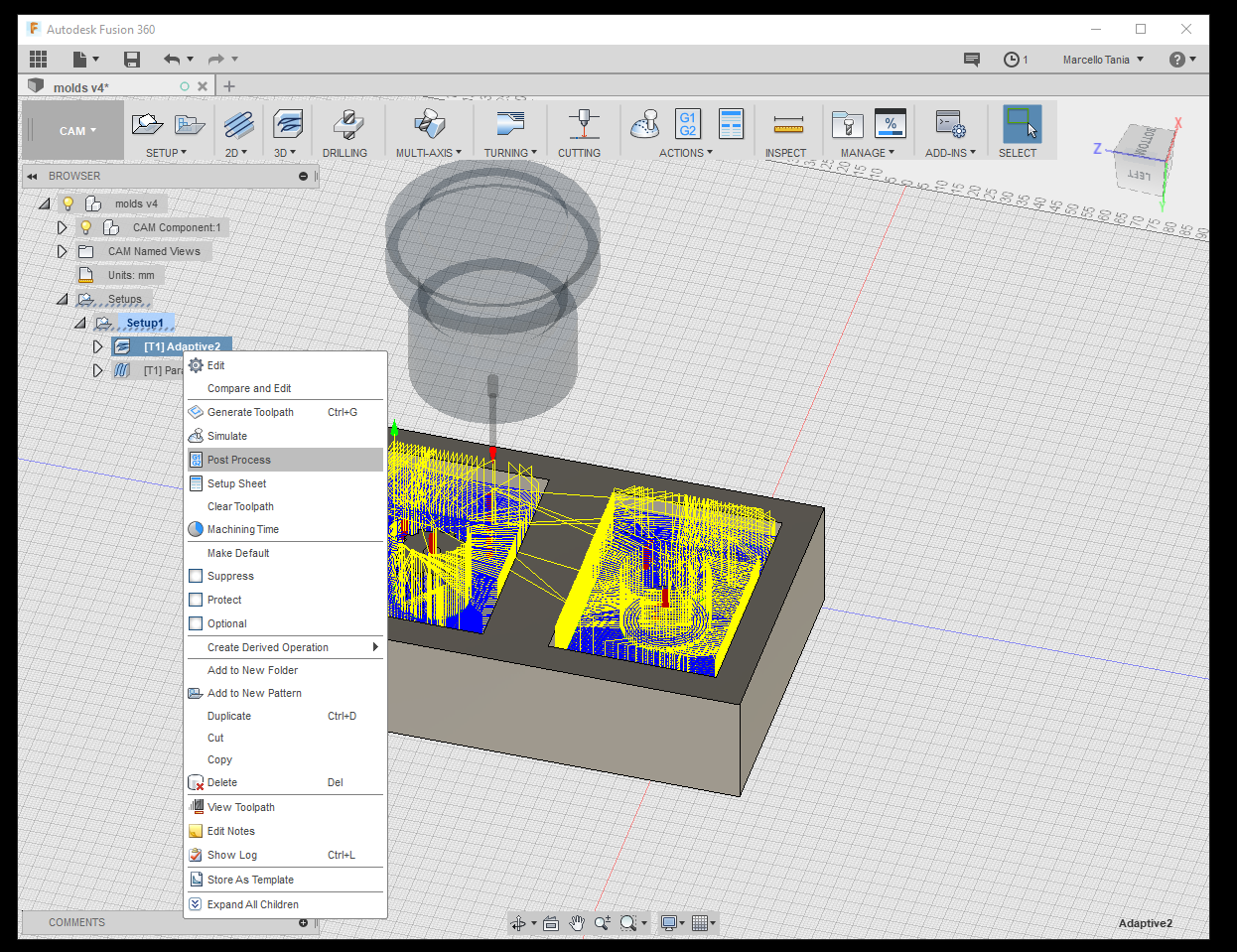
Right click on the stratergy and select post process.

Select Roland RML, machine type is MDX-40 and click post to save the g-code.
4. Disaggreagation
After work on the CAM it is to time to CNC the work piece that we have generated.
4.1 Unit Objective
Fig. 6 Main group of manufacturing
Cutting or disaggreagation is one of the six main groups of manufacturing technologies. However unlike shaping cutting is removing the workpiece
4.2 Molding
First of all we are going to make the molding by milling a box of blue wax using roland mdx-40aCNC.
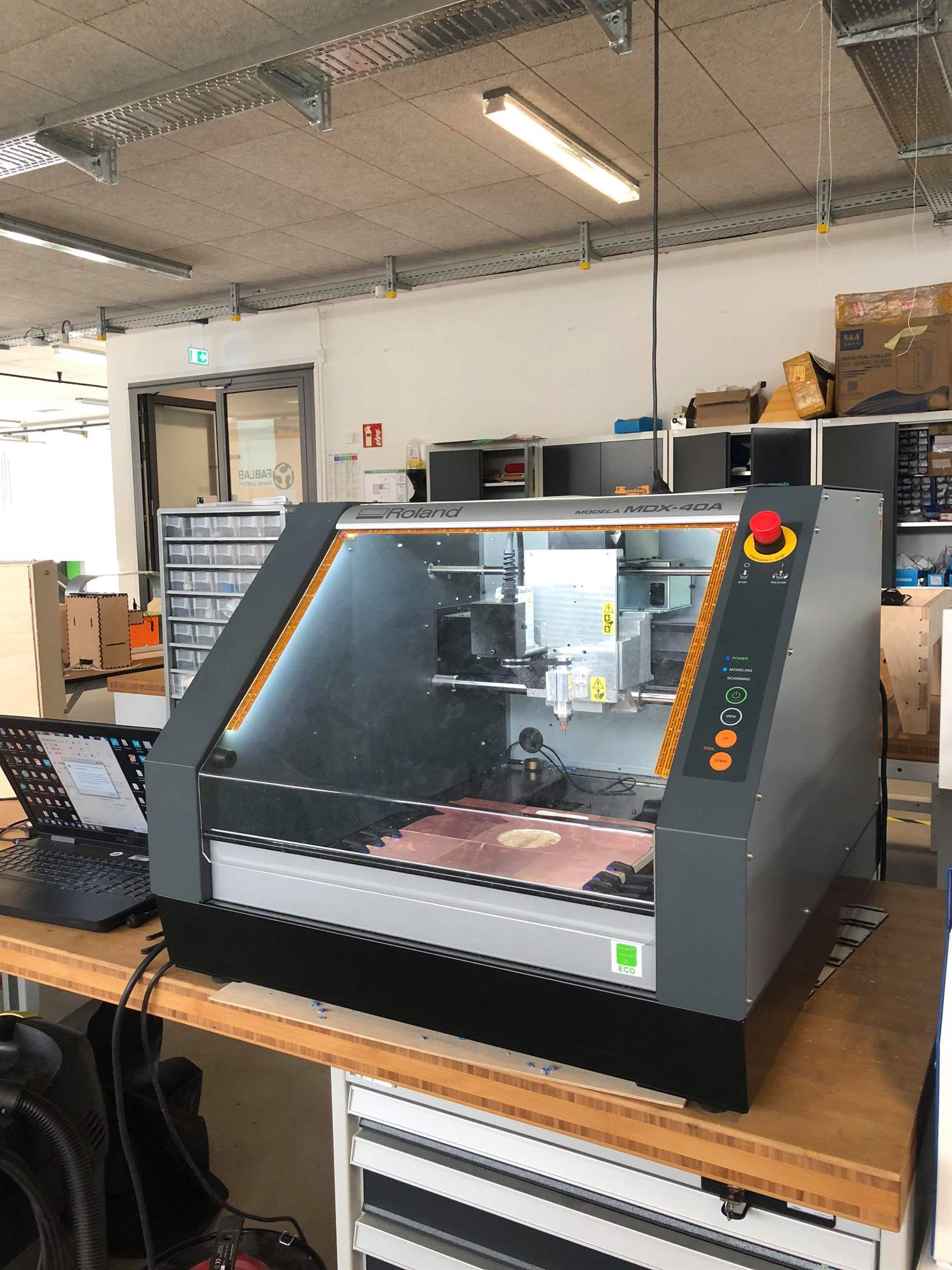
At the begining initialise the home postion by opening the Roland Vpanel software and start to mill.
This is the result that you would like to see.
5. Casting
5.1 Preparation
After milling the original mold, we will have to create a second mold with silicon because wax melting point is low compare to silicon. The chemical mixture of the casting will be quite warm that is why we are creating the molding with silicon.
To build the molding I used a piece of plywoods, clamper and silicon glue.
Make sure that there is no leaks in the stock because we are going to pour a silicon liquid.
5.2 Silicon Mold
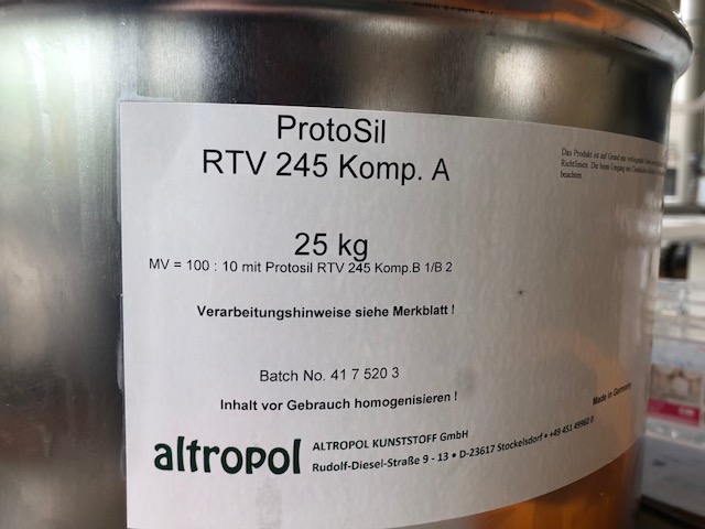
This is the Protosil RTV 245 komp.A
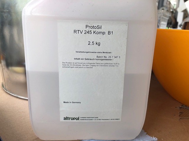
This is the Protosil RTV 245 komp.B
In the casting, I molded it with a silicon rubber, Protosil RTV 245 silicone.
5.2.1 Protosil RTV 245
I took a look on the data sheet and it is writen that the mixing ratio (100A:10B1), pot life is 80 mins and cures time is 24 hours.
5.2.2 Mixing
Mix the silicon with the harderner and pay attention to the mixing ratio by comparing the mass of each chemicals.
Mix them together.
And then pour them in the box that we have made.
5.2.3 Vacuum
This process will suck the air bubbles inside the mixture to come out so we will not have any bubbles in the molding.
Keep it inside the machine after sucking the air for a while in the vacuum chamfer.
5.2.4 Cure Time
Let it dry within the cure time and
Remove the plywood to get he silicone mold and I used pressure gun to easy to disamble the silicone rubber.
The result should look like this.
6. Casting
I used the resin NEUKADUR ProtoAmid 60 to cast the gear.
6.1 Datasheet of NEUKADUR ProtoAmid
The properties of this material is very high impact stregth and used for small production, prototzping and samll production of technical parts.
6.2 Preparing the Molding
This is two sided molding therefore I have to make sure that thereis going to be hole above to pour the cast and two parts are tidely close to prevent any leaks.
7. Result
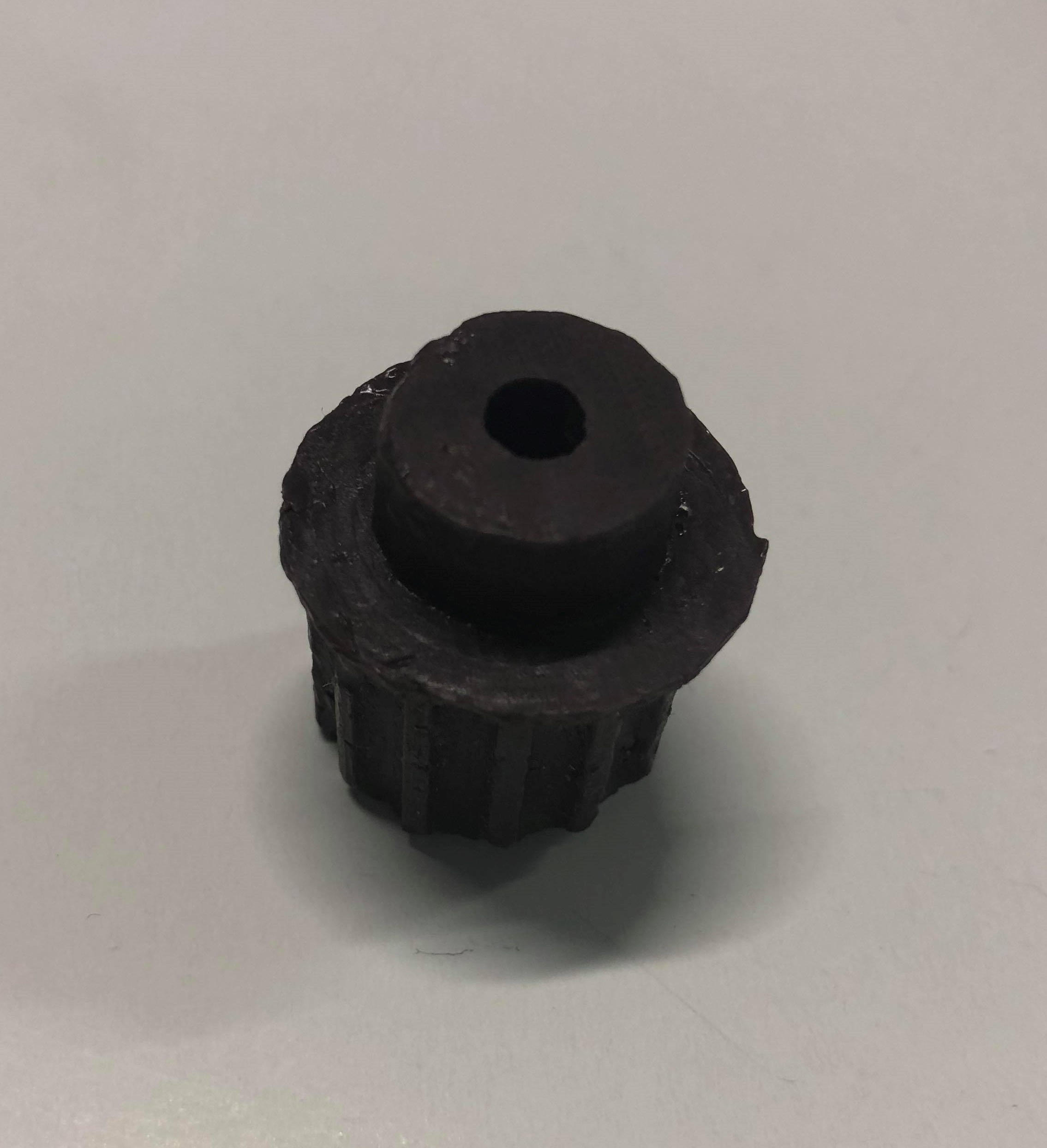
The result was not that good because of bubbles. The bubbles were created in the pouring the mixture to the silicon molding. It is very hard not o create a bubble because there should be another hole to let the air reliase outside or maybe do it the vacumn chamfer machine.
References
Downloads
3D Cad of Molding and g-code