Contents
1. Task
2. 3D CAD
3. 2D Drawing
4. Big CNC
5. Result
9. Download
1. Task
Make something big (on a CNC machine).
2. 3D CAD
I am modeling my rocking horse with 3D CAD to take a look it clearly before machining it.
.png)
Sketch the part and then I extrude 18 mm regarding of the thickness of the material.

To have a press fit and have some clearance so I can assembly them together with another part and a good corner. I drew circle of a diemeter of 10 mm to have distance more than 6 mm because the end tool diamter is 6mm.
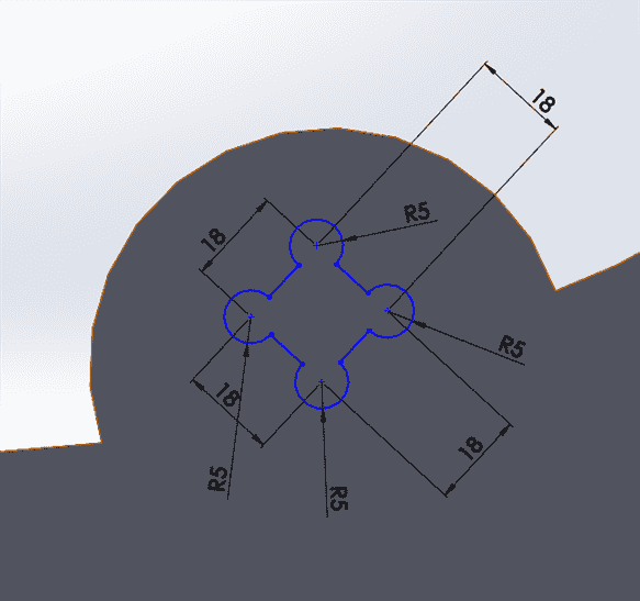
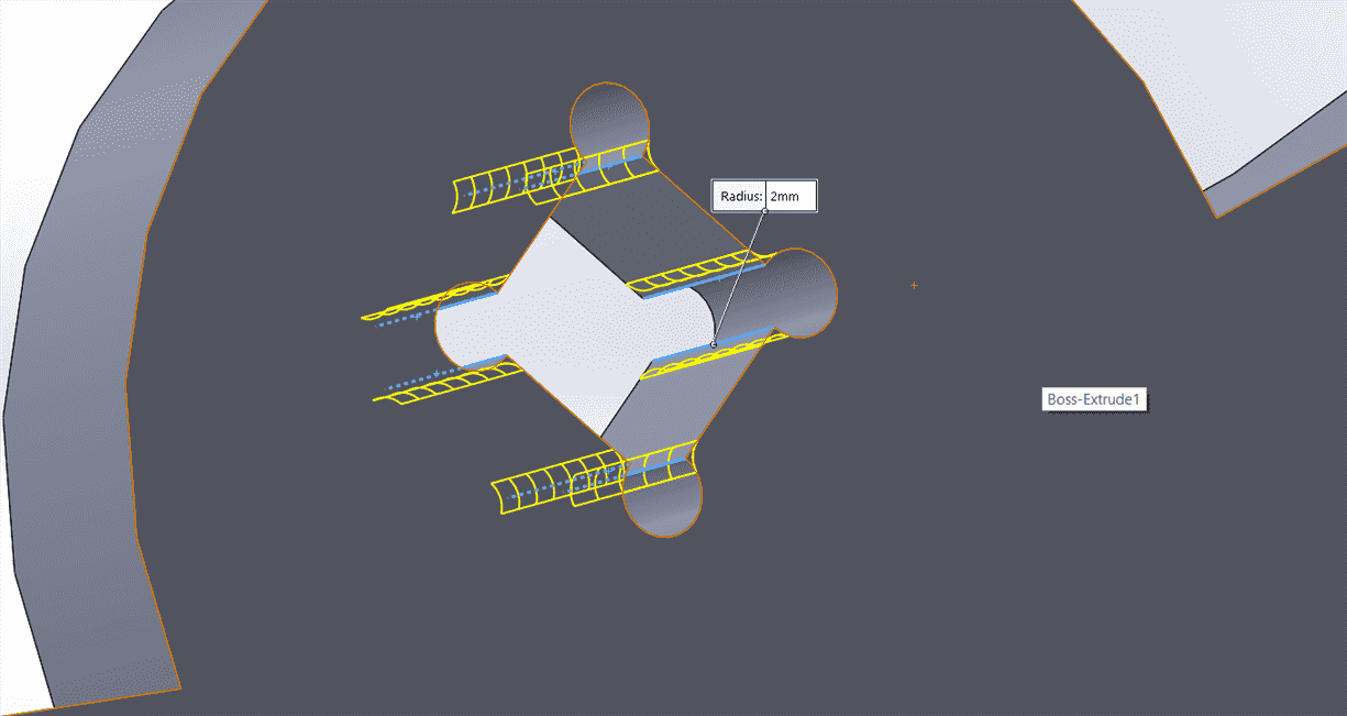
For not having a sharp edges, I was also adding 2mm filet at the interlocks.
3. 2D Design
Draw the 2d drawing in solid work with one view that I would like to cut and export them into dxf file.
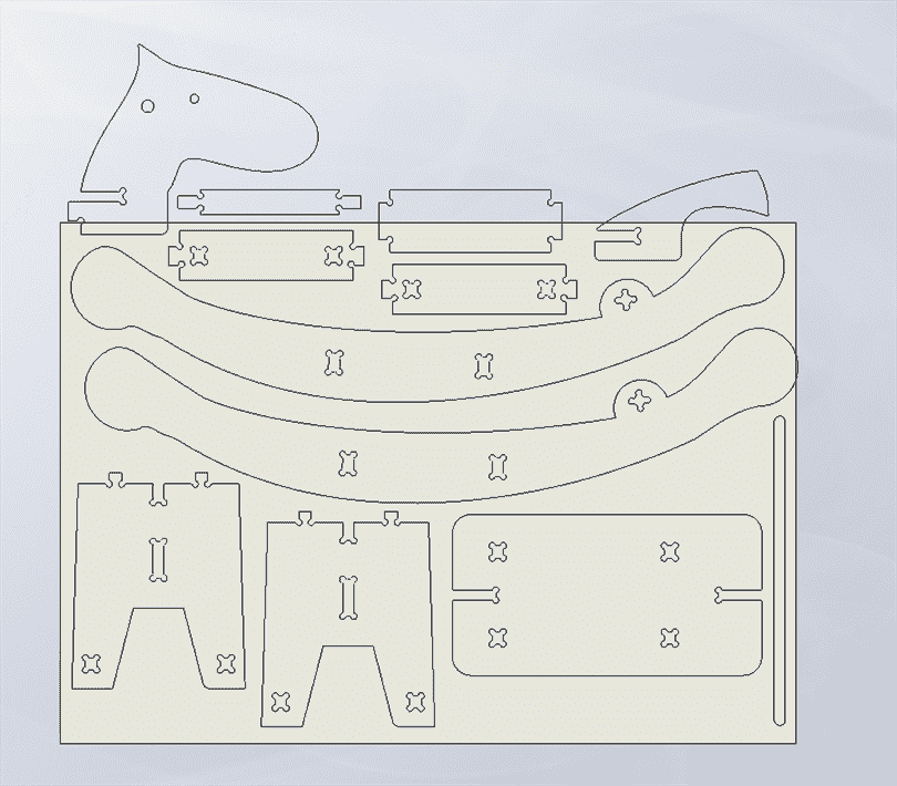
Join, set the layer into Default, choose display color by layer and set the print width into by layer to all the drawing.

Set the layers for cutting the inner part, outside part, the material and cut the material afterward.

Draw the 2d drawing in solid work with one view that I would like to cut and export them into dxf file.

Then save them into dxf file.
4. CNC
Safety!
It always good to know how to turn off the machine before start to turn on the machine, so there are 2 ways to turn of the machine: first is by clicking the ESC key on the keyboard and second is by pressing the one of the emergency button.
After the emgency button
If you are in the middle of machining your work, do not worry because you could still continue your work. So first of all make sure that zour work coordinates and go back the process by starting the machine again.
Start the machine.
Start the machine by pushing reset and then start button. You will hear the machine waking up.
Open the air valve to activate the vacum otherwise the SPS light will turn on if the air valve is closed.
Open the CNC software on the computer.
Press start.
Changing the tool
There is a holder to open the tool from the holder and place it there. Open the holder with a wrench and now you can replace the tool. After you have fixed them nicely, measure the tool.
Click F11, F3( user)
0 is to put the tool back
F3 to shift the z axis
Input the tool number, tool length and tool diameter.
You could do it automatically by using the sensor too.
Put the material
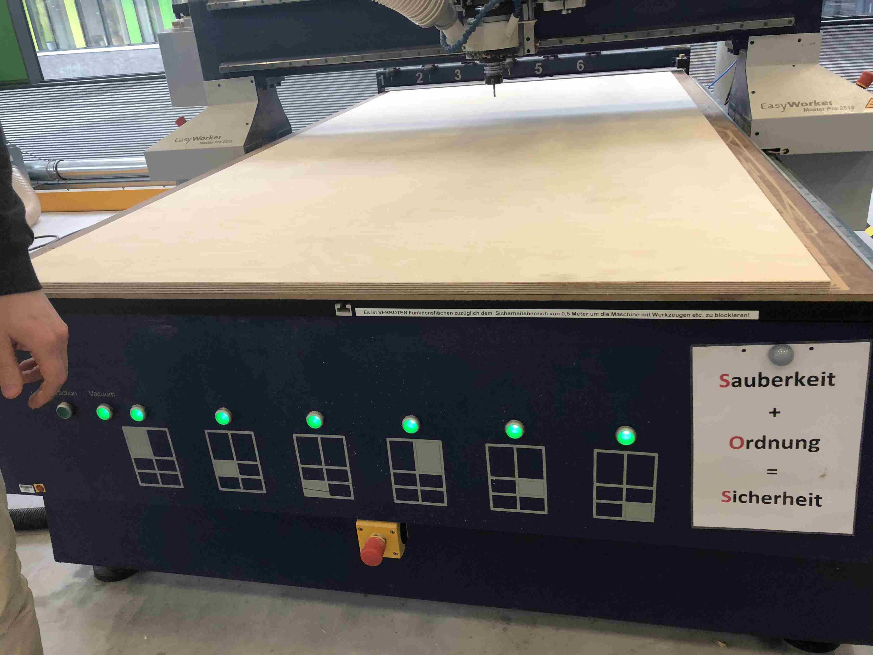
Make sure that the material is align properlz and turn on the vacumn and then making sure that the workpiece is hold properly.
Home the machine.
Click the home squence to enable the driver.
Change the axis by using the arrow keyboard or press on keypad of the machine by pressing the arrow and the button on the right side of the keypad.
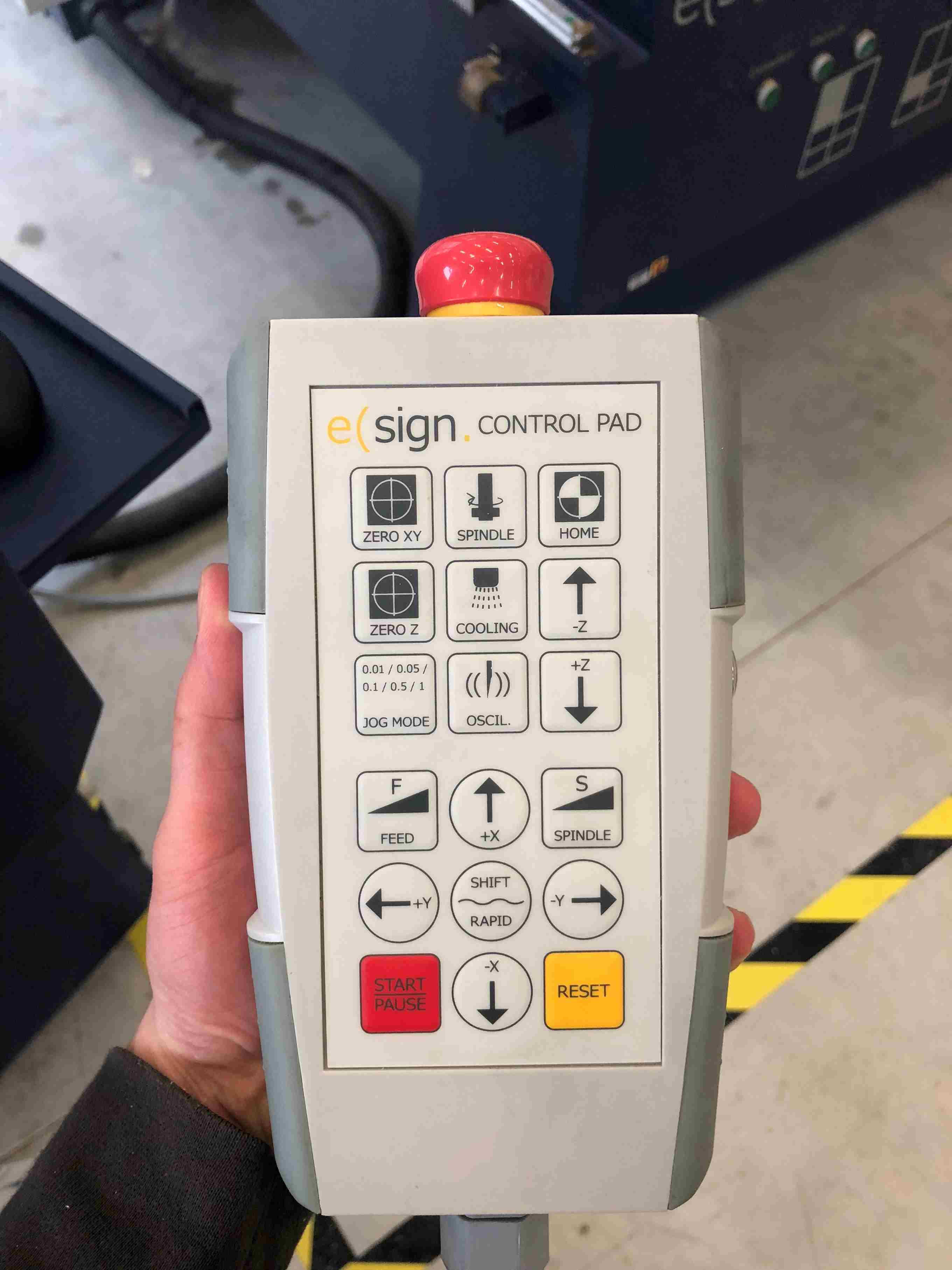
Calibrate the z axis
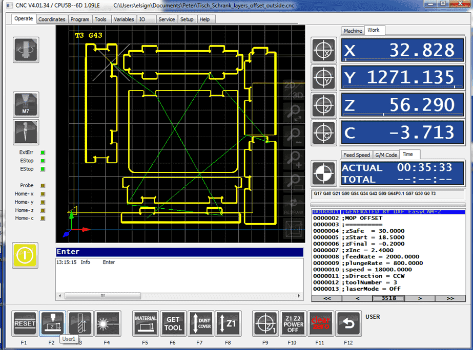
Use the sensor by press F2 and place the sensor exactly below the end mill.
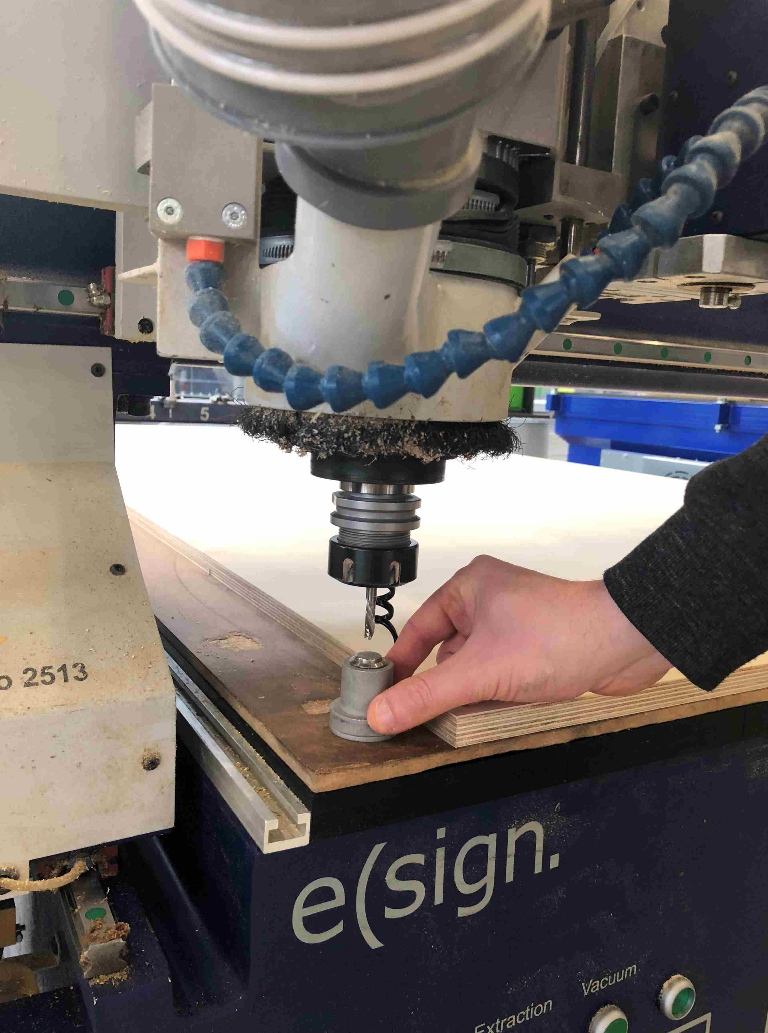
or manually by enabling the simple and open the dust cover.
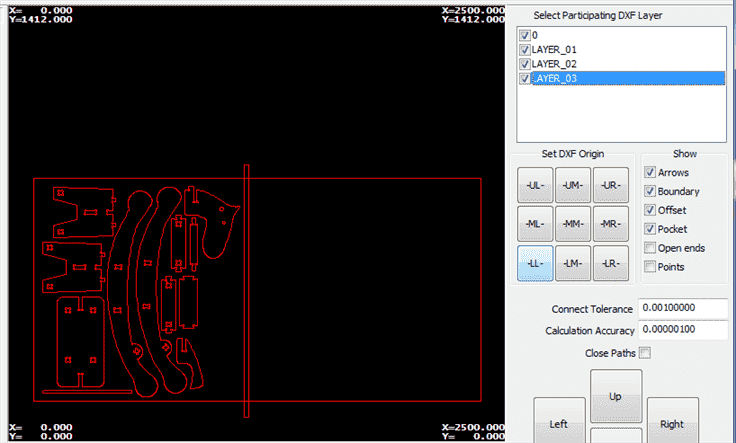
4. CAM
cick nav on the navigator bar
click program
Set the origin
Insert parameters offset or cut out
Inside CW for the holes in the inner part
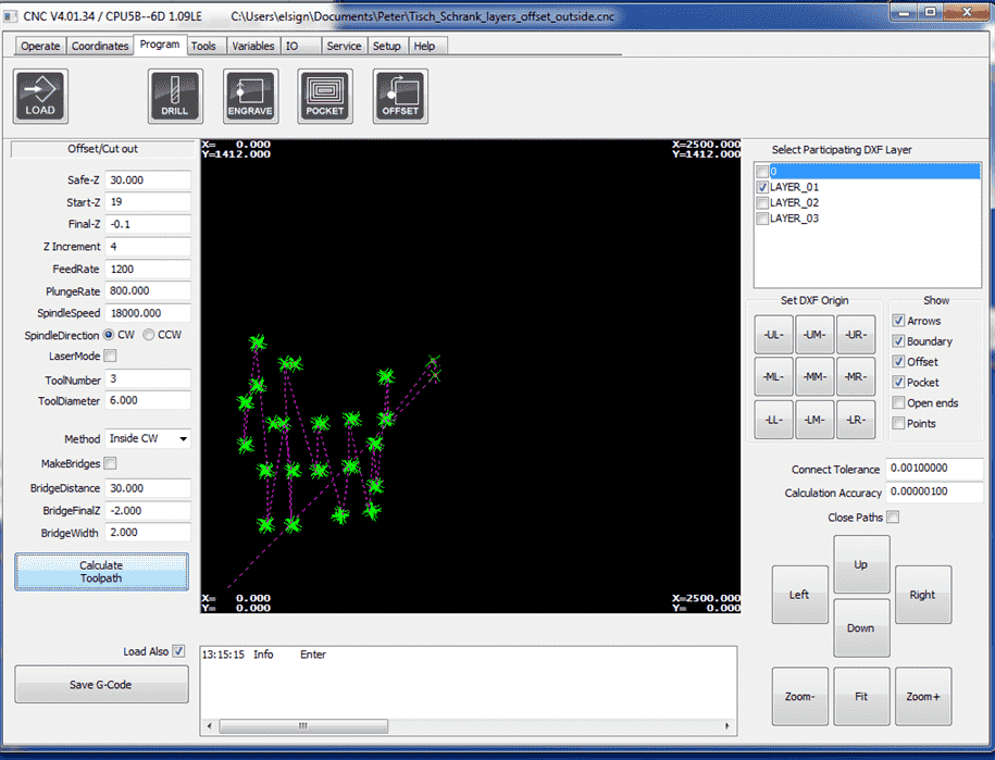
Inside CW for cutting the outer part

Double check the parameters!
Press calculate G-code
Activate the dust holder and turn on the vacumn.
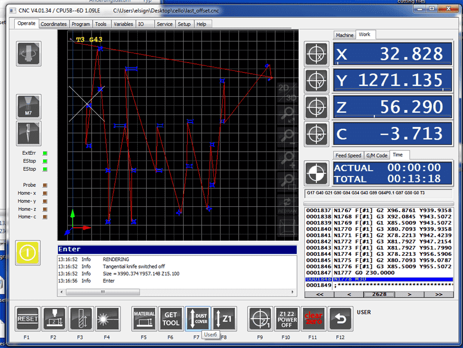
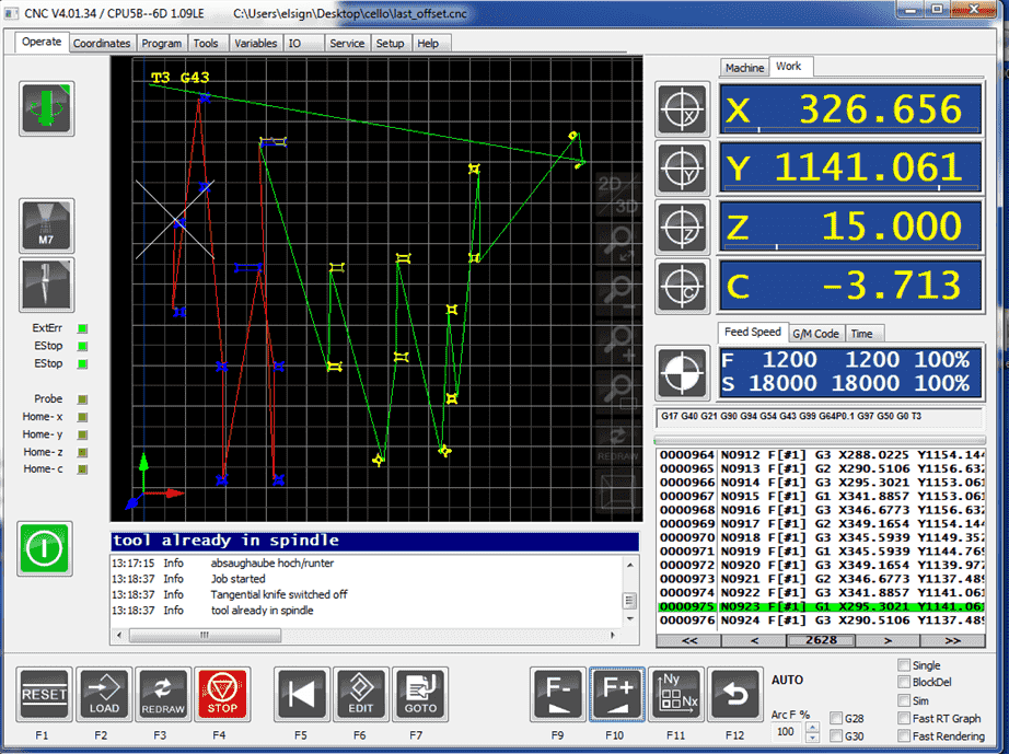
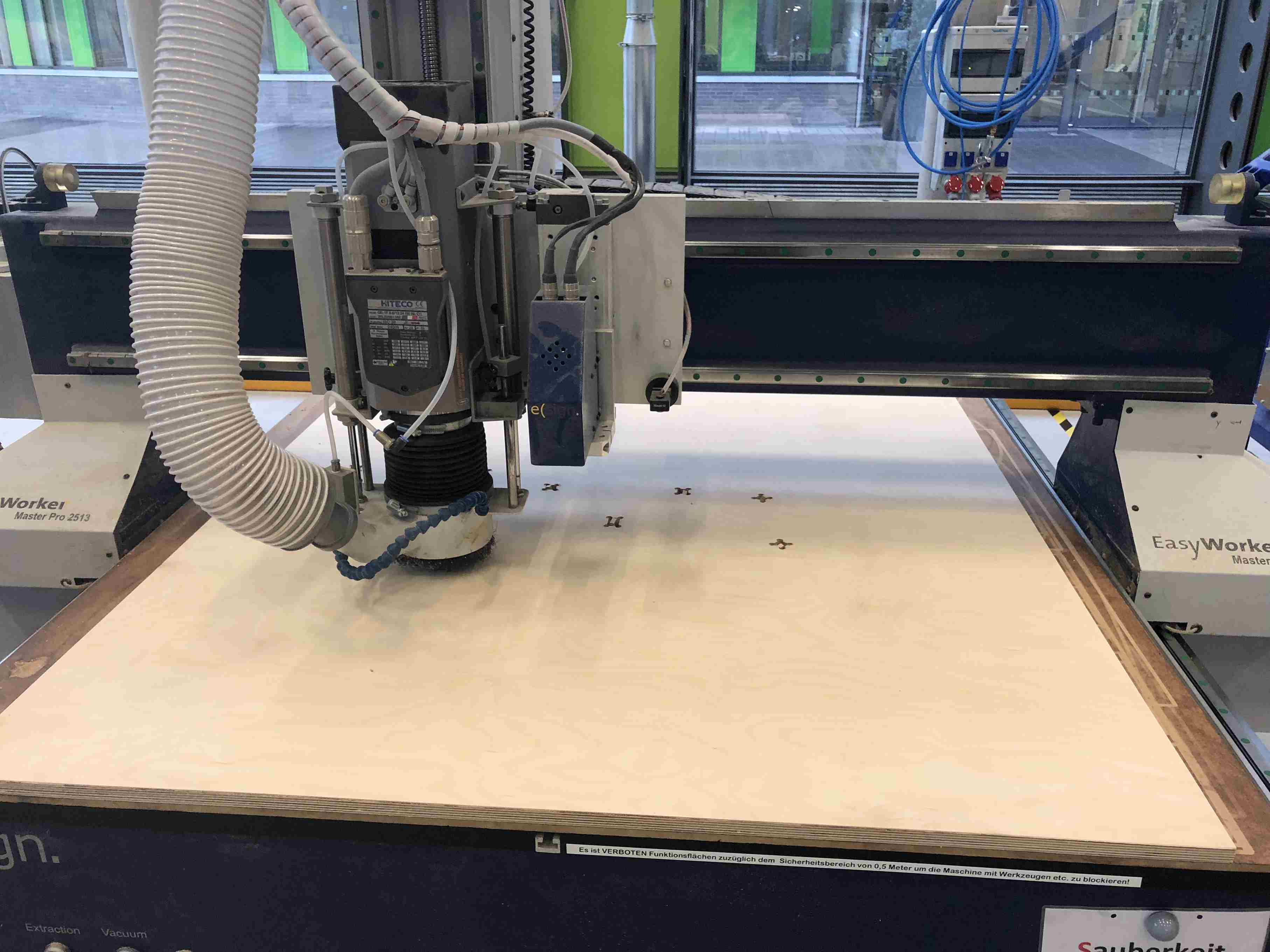
Start to run
5. Rocking Horse
Prepare the parts

Assembly the parts

Result
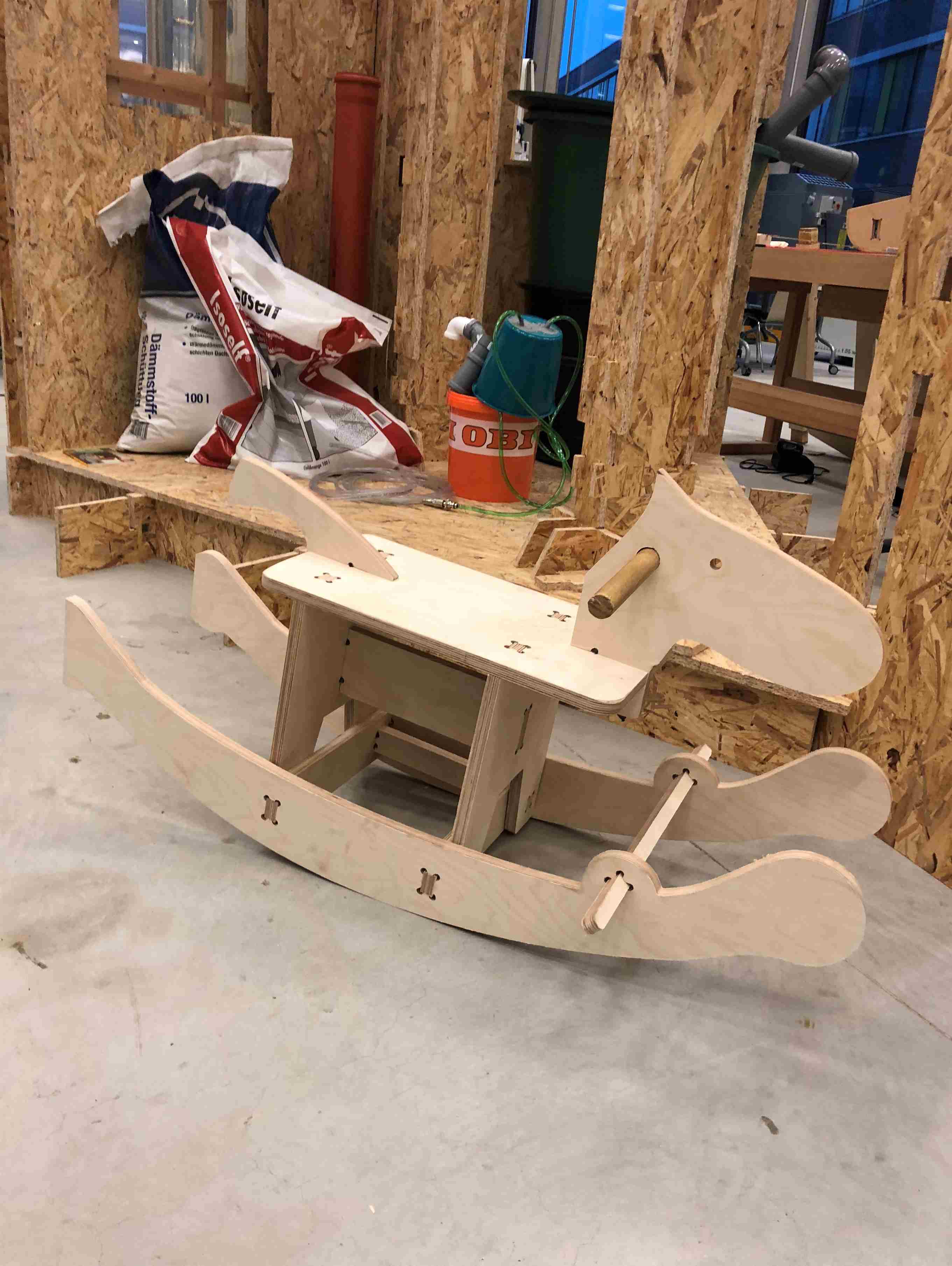
Time to play!
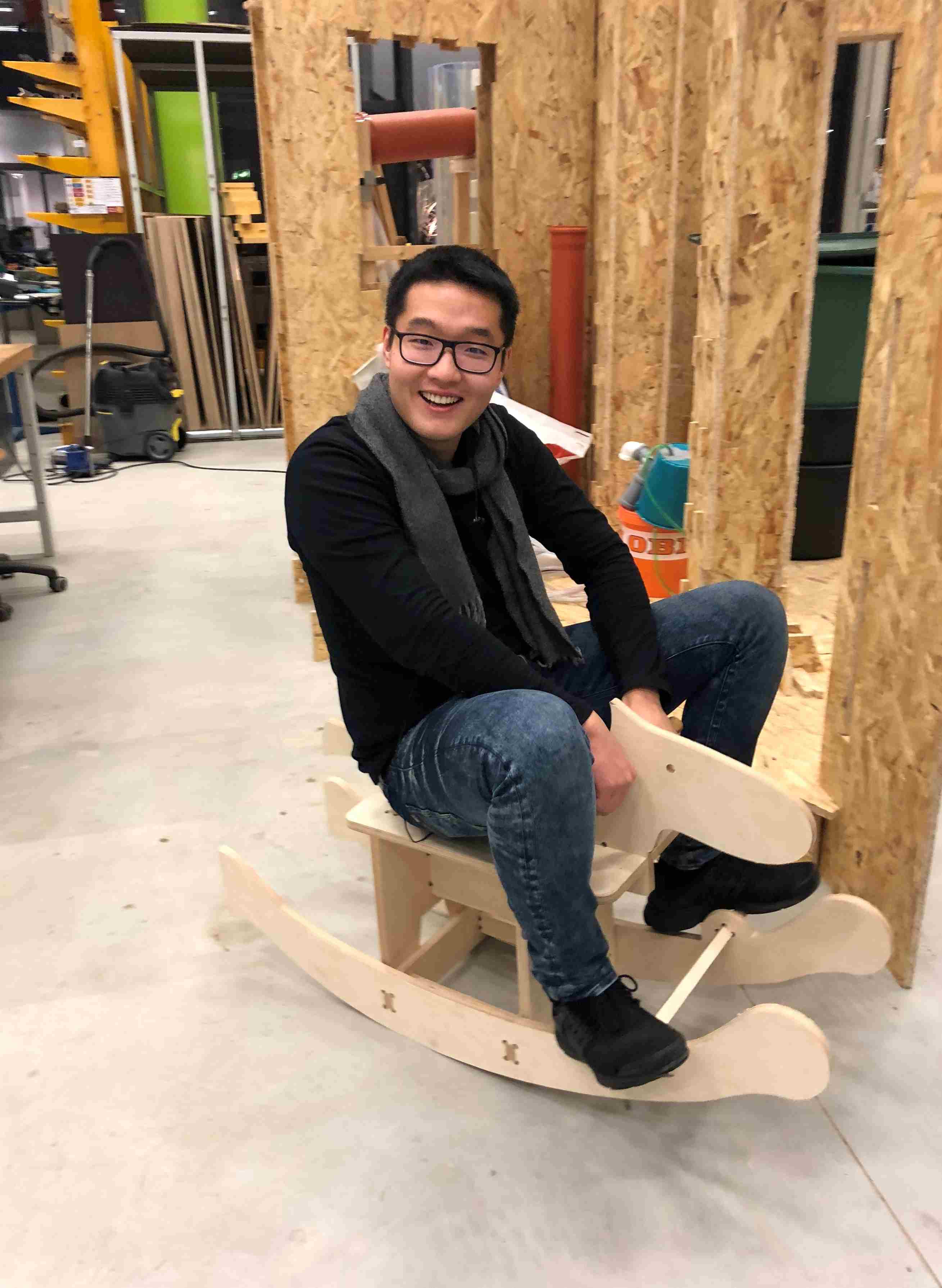
WUHuu!!!

Download
DXF file.
3D CAD.