Contents
Additive Manufacturing
1. Objective
2. Introduction to 3D printer
3.0 Principle of 3DP (3D Printing)
4.0 Data exchange file formats for AM
5.0 Supports
6.0 Robotic Arm
6.0 3D Scanner
1. Objectives
In this assignment, I have designed a robotic arm and then 3D print some of theparts that culd not be made subtractively. Moreover I tried a iSense 3D scanner.
2. Introduction to 3D Printing
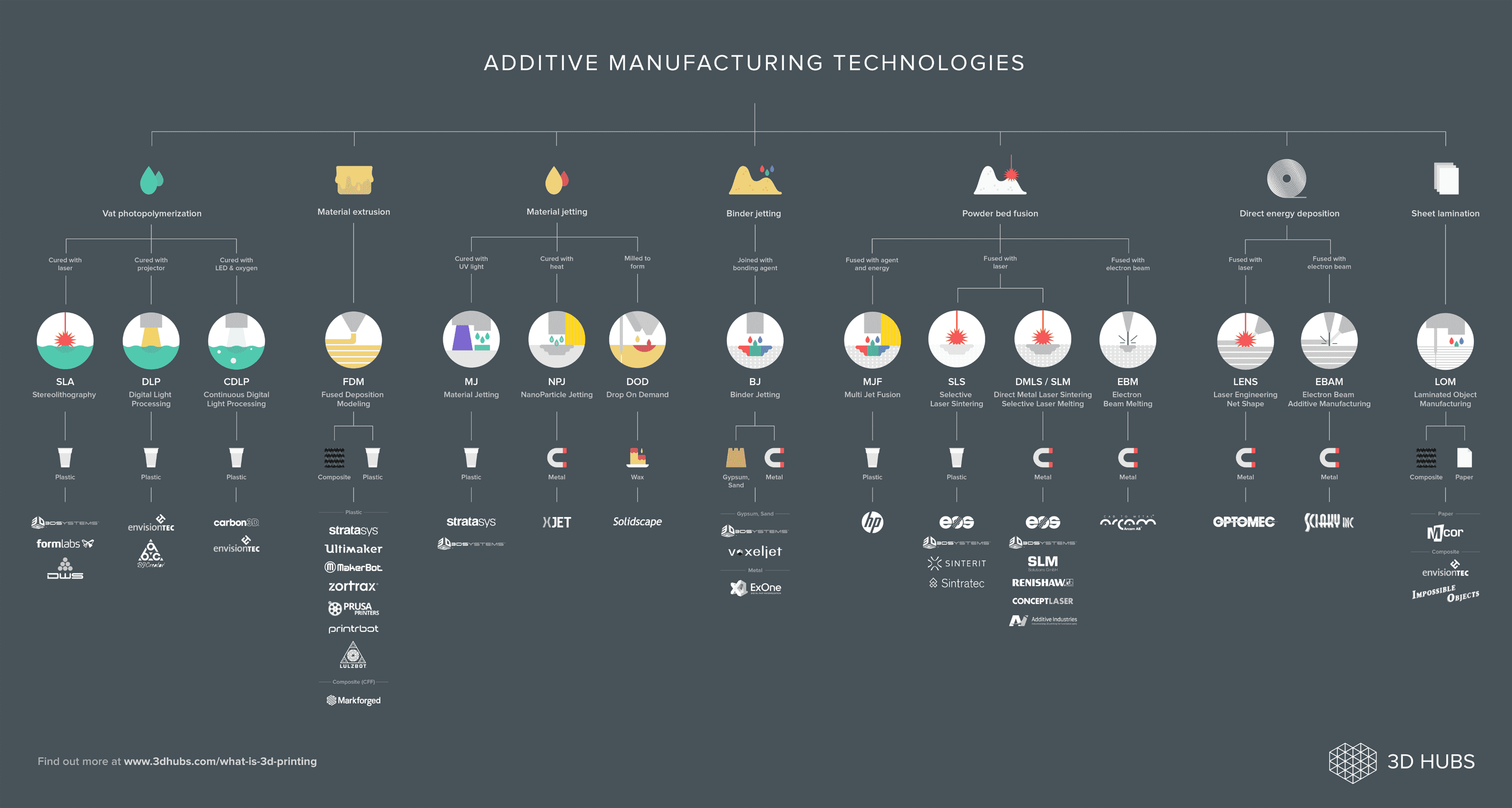
Fig 1.0.1 : What is addictive manufacture? Resource: 3d hubs
Additive Manufacturing is know by many names: 3D Printing, Rapid Prototyping, Rapid Tooling, Rapid Technologies, Rapid Manufacturing, Advanced Manufacturing, additive Fabrication, Additive Layer Manufacturing, Direct Digital Manufacturing and Direct Manufacturing. Today additive manufacturing focuses on features such as geometric freedom and speed is not he sole determining factor.
Unlike most conventional manufacturing techniques, Additive manufacturing forms oject bz building matter up, rather than removing it.
Additive manufacturing technologies are use to manufacture: Prototypes, tools and production parts.
2.1 Advantages of AM in Production
Potentials
2.2 Disadvantages of AM in Production
Potentials
3.0 Principle of 3D printing (3DP)
3.1 How it works
3.2 Pro
3.3 Con
Machine suppliers: Most common technology for desktop 3d printing.
4.0 Data exchange file formats for AM
This is a very common way to save your 3D CAD model and there are some charteristics and what can be wrong with this alogorithm.
LMI, VERML, CS, RPI and STL,etc
STL - orifinally STeroLithograpy, today Surface Tessellation Language also known as Standard Triangulation Language
4.1 Characterisitcs of STL
4.2 Quality issues due to Tessellation
After tessellation following erros can occur:

5.0 Supports
Supports are used when models have sttep ovehangs or unsupported area
A general rule of thumb is that most printes can support ovehang angles less than 45 degrees
6.0 Robotic Arm
6.1 Sketch Idea
First of all I sketeched my idea what I am going to 3D model and some of the feutures of the robotic arm.
6.2 Part List
I am planning to use a 3d print and laser cut a plywood to fabricate the robotic arm.
Part list:
6.3 3D CAD
3D CAD of the robotic arm that I am going to build.
6.3.1 Head
To model this is simple you have to design so that it can hold the servo motor and assembly this to another part.The feuture I used to model this head part is boss extrude, mirror, filet and cut extrude.
6.3.2 Shoulder Join
As you could see this object cannot be produced because the inside of the part should be cut and a CNC milling machine head tool might be to large to cut this.
6.4 2D Drawing
After I have modeled the 3D CAD using solidworks, I made a new 2d drawing and put all the parts that I want to laser cut.
6.5 3D Print
6.5.1 Cura
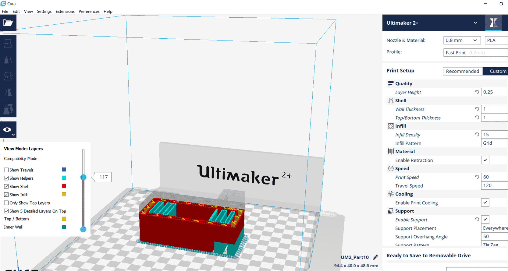
Cura is the software to generate the g-code of a 3d printer and set the properties.
6.5.2 Printing properties
It is time to print two parts of the robotic arm, the head and he shoulder join and I was printing with Ulimaker 2+. Printing PLA is quite easy because it melts in a low
Ultimaker 2+
Print setup: Custom
Start to print and it takes arround 3 hours to print.
Remove the support from the material
6.6 Assembly
Assembly the 3d parts to the plywoods with m3 screws.
Finally we have a robotic arm!
7.0 3D Scan
7.1 A Chair
The assigment is to 3D scan an object.
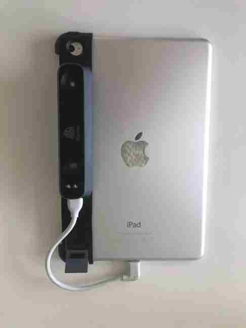
The 3D scanner that I use in our FabLab is called iSense which is attached to an Ipad.
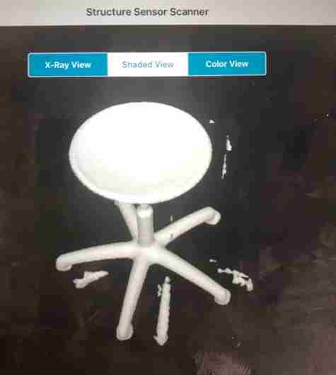
This is my first experience using a 3d scanner and the result is not that bad.
We will have to rotate 360 degree and move up and down to scan the object.
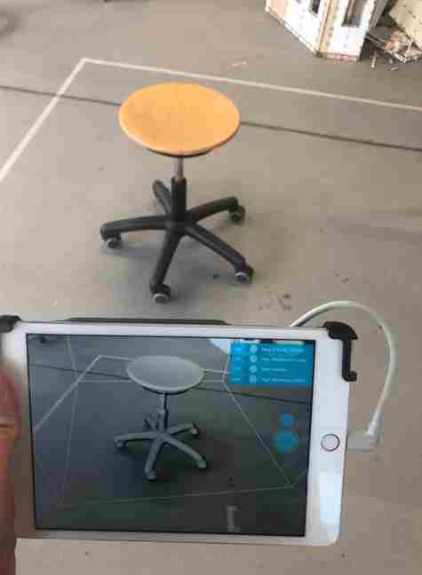
The result for shaded View.
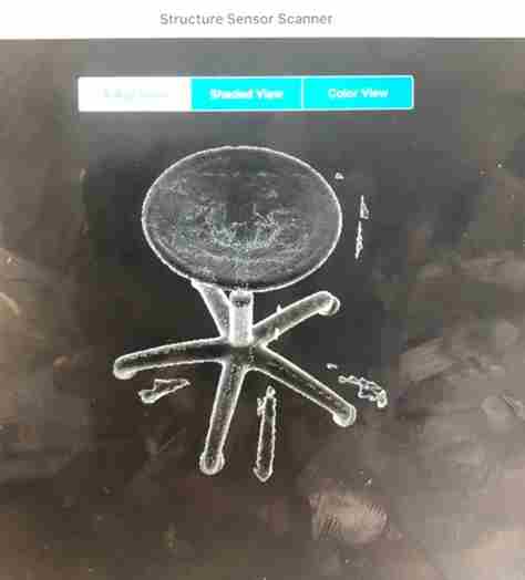
The result for x-Ray.
The result for colour view.
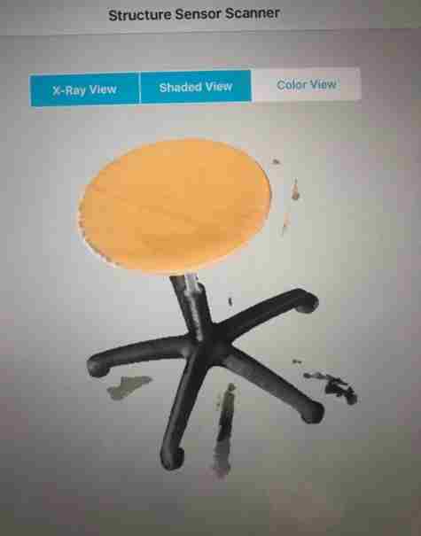
This is the overall view of my first experience of using a 3d scanner.

7.2 My dad
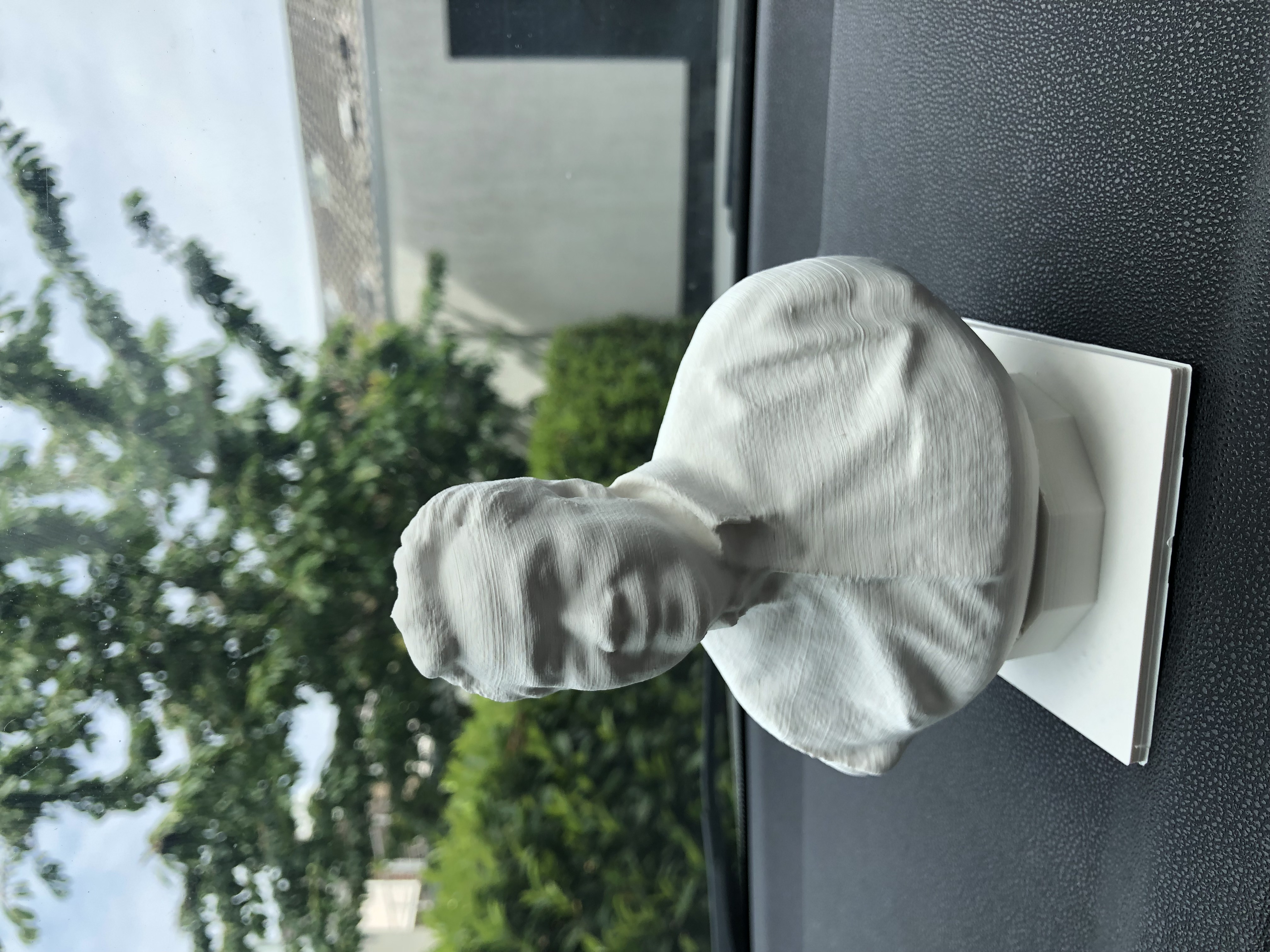
The harware I used to 3D Scan was actually my Iphone x with ScandyPro software in IOS.

Then I tried to 3D print it and the following picture was the result
8. References
9. Download
Robotic Arm 3D CAD
3d Scanner file