Contents
1. Introduction to PCB Milling Machine
2. Milling and Soldering PCB
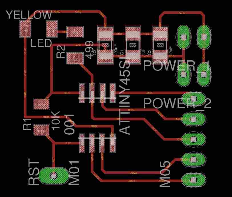
3. Installing ATtiny support in Arduino IDE
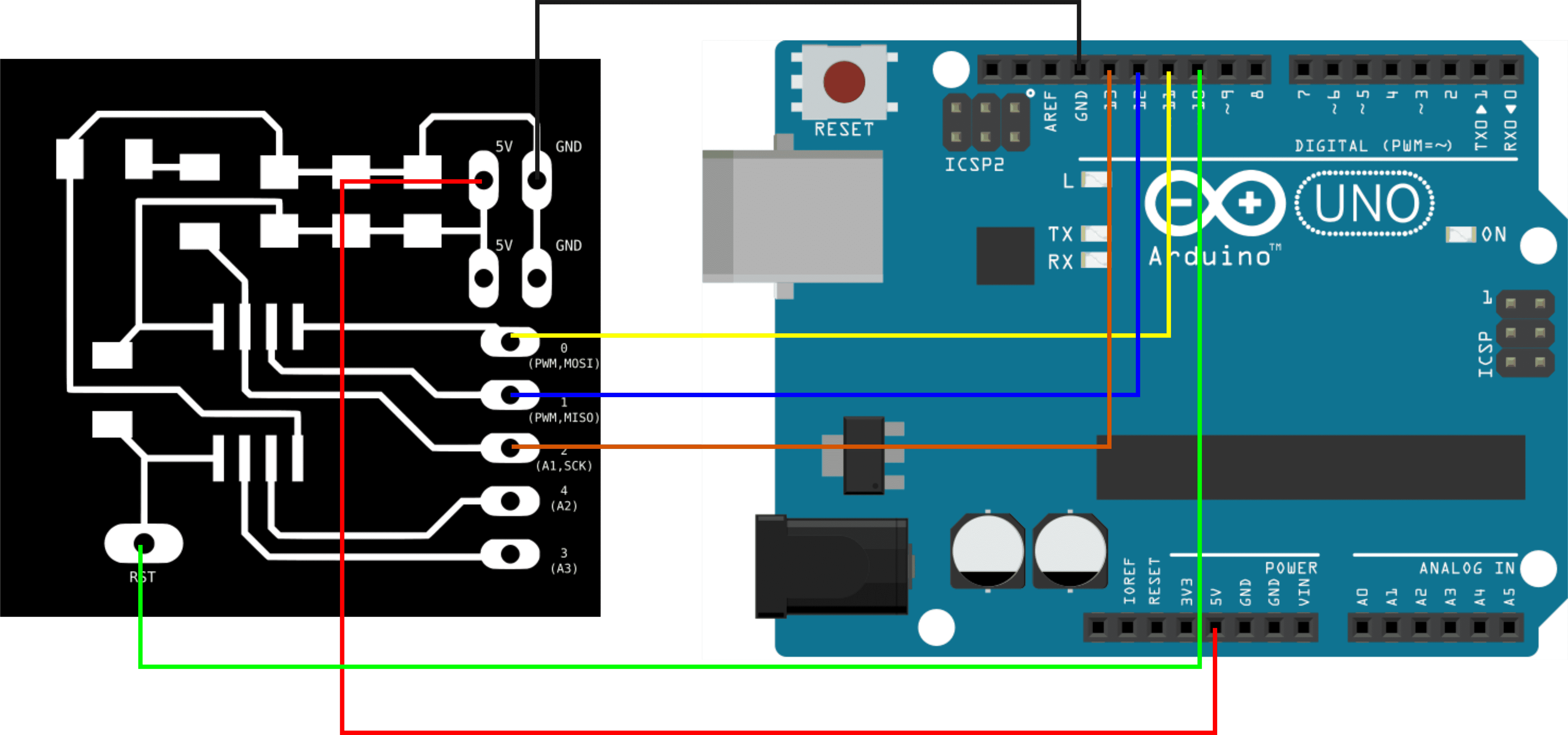
4. Bootloader ATTiny 45 using Arduino Uno
5. Fab ISP
6. Software installation
7. Reference
8. Download File
1. Introduction to PCB Milling Machine
Before starting to make a PCB, you would need to design your electronics components on eagle and then mill it to produce the PCB.
I have milled a PCB in FabLab Kamp-Linfort to practice before milling the fabISP.
Open the schematic in Egle and edit if you would add more components.
Design or just open the board .
Select only tops and pads layers.
Export Image into png file and set it into monochrome with 1500 dpi resolution.
Edit the picture of the PCB with GIMP or any other editing image software.
Select the Rectangle Select Tool B put the circuit into box.
Click the select menu, choose "Rounded Rectangle", select > rounded rectangle and press OK, this will make a filet and and Image > Fit image to selection Press CTRL+X.
Safe it on another file as the image to cut the outside board.
Open this website,Fabmodules.org to make the GCode.
Upload the PNG file, select the appropriate machine eg.Gcodes (.nc) and PCB traces (1/64)
This is the setting to engrave that I use to CNC the board.
On the CNC set the home point, upload the gcode and start to run the CNC.
The following is the set for engraving and cutting:
Engraving:
Cutout:
Useful gcode command
Other Information: for Roland MDX-40A CNC setting:
Engraving:
2. Milling and Soldering PCB
After you have generated the g-code which is the CAM to run the milling machine you are ready to cut the PCB and solder all the components.
Drill the the hole with the required diameter for the male pin headers. eg. 2mm
Please do not use a sucker for removint the lead because there will be a higher chance that the cooper of this PCB will be destroyed.
I learnt this by helping my friend and end up destroying her PCB. :)
3. Installing ATtiny support in Arduino IDE
4. Bootloader ATTiny 45 using Arduino Uno
5. Fab ISP
This is the FabTiny ISP board that I have got from Andy.
In this chapter, we are going to mill our FabTiny ISP via Fab Modules or Mods. Afterward, program it using the programmer that we made.
5.1 Introduction
FabTinyISP is a programmer board with an AVR ISP board that can be milling in a fab lab.
5.2 PCB Fabrication
Download the PNG files for the traces and the board outline.


To generate the G code, visit the Fab Modules.
A black and white image is required to to maximize the CAM from fabmodules, upload the png image on the first bar. The second option is depending on the machine, since I used the Roland MDX-40A. The third option is for choosing the process.

The next step is to set the parameters. The origin point is set into x0,y0 and z0, with a speed of 4 mm/s. The tool diameter is 0.2 mm. The offset overlap is how much area will the trace cover the previous pass. The number of offsets you milled will increase the machining time as you increase the offset. Since I would like to make sure only to have the traces and all the remaining copper is removed, it should be set to -1. Then click calculate and we can see the calculated tracks and then save to download the g-code.
Roland MDX-40A CNC setting:
Engraving:
Cutout:
5.3 Preparing the copper boards
Since the milling machine only knows that the board is flat, we have to make sure that board is not uneven. Therfore glue them nicely with double tape and the press them on a flat plywood.
5.4 Vpanel
Vpanel is the software to run the milling machine. The buttons x,y,z are to move the table according to the direction. Firstly, we have to calibrate the system to get the home position and the hard part is to touch the z driection down to just touching the surface. After set the origin point on the GUI. Click Cut and then upload the G-code that we have downloaded from the fab module. The CNC will mill the the PCB board.
After milling the PCB, this is the finished PCB looks like.
5.5 Assembling the PCB
The part list to make the Fab ISP:
Solder all the parts and be sure that you solder the diode in the correct possition. A good solder will look shining
This picture depicts how we can solder a component put the soldering in between the cooper plate and the wire and place the solder wire.
Basically, we could judge the soldering by simply looking at the soldering. It will be good when the solder is shiny and shape like a volacono mountain.
5.6 Check your work
Well it may seem to early to start debugging yet it always help you to save a headaches down to the road and it only takes a couple of minutes. Check your board from the schmatic and PCB layout image to make sure that you have installed the correct components in the correct possition and orientation. Inspect your board visually that all the components is connected properlly and there is no unwanted solder bridges between the traces and pins. Lastly handle a multimeter to check for shorts between Vcc and GND.
6 Softawre Installation
6.1 In System Programming
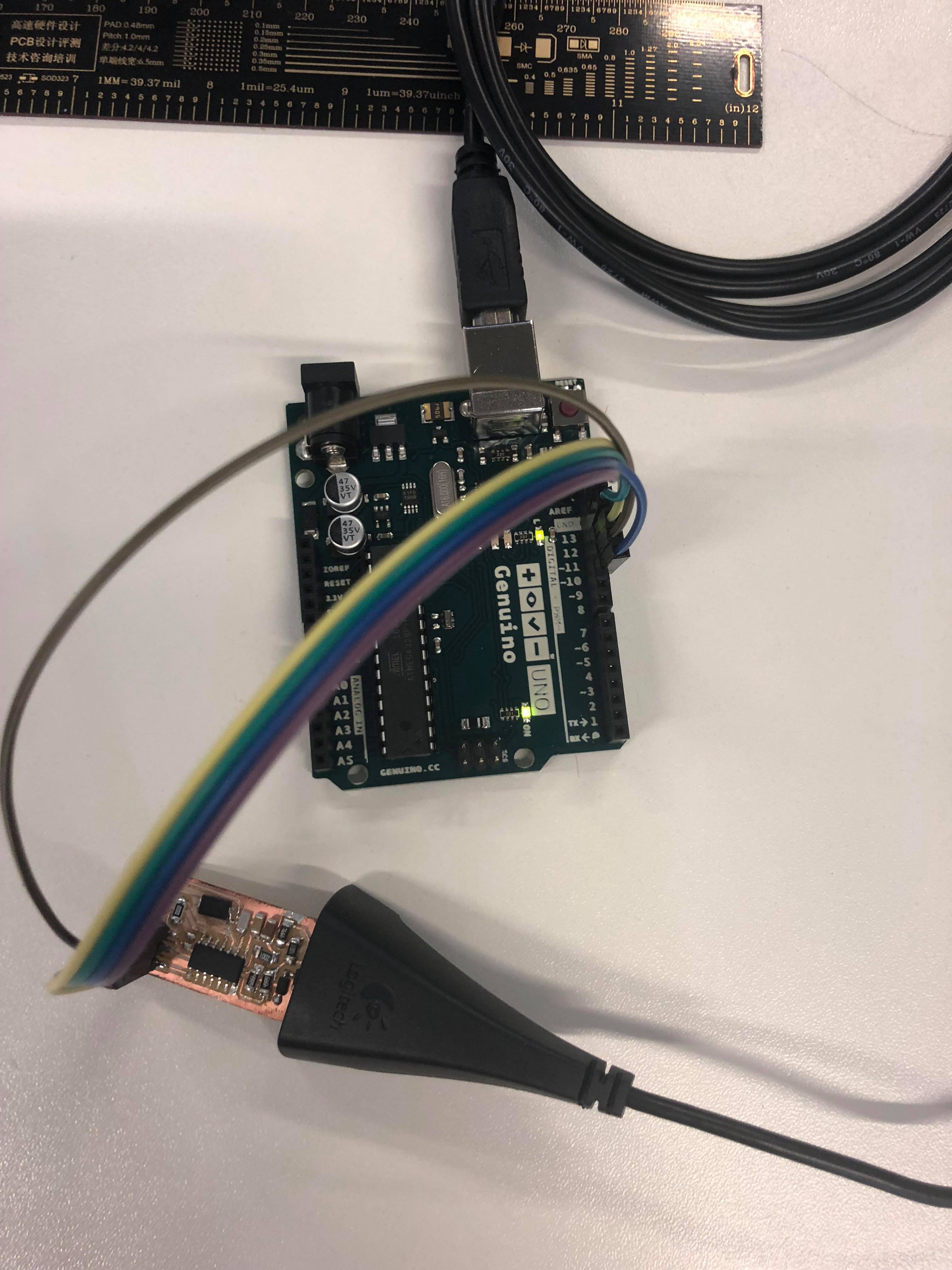
To programm an ISP, we will need to pre programm the chip and used another microcontroller like arduino UNO.
6.2 Install AVRdude/ GCC sotware
Linux
You will be using a command line shell to install and upload the program in the terminal. If you are not familiar using a command line shell, you may review a tutorial.
Open Terminal and type:
sudo apt-get install flex byacc bison gcc libusb-dev avrdude
Then install gcc-avr
sudo apt-get install gcc-avr
Type "y" to agree.
Type the following to instal avr-libc
sudo apt-get install avr-libc
This is might be already installed.
sudo apt-get install libc6-dev
6.3 Download and Unzip the Firmware
Move to desktop
cd ~/Desktop
Download the firmware from the Fab Academy Electronics Progduction page.
wget http://academy.cba.mit.edu/classes/embedded_programming/firmware.zip
Unzip the firmware
unzip firmware.zip
6.4 Program the ATtiny84
Edit the Makefile
After unzip the firmware, type the following command
open a text editor
nano Makefile
Open a text editor and Replace the following command
                              DEVICE = atTiny44


                              AVRDUDE = avrdude -c avrisp2 -P usb -p $(DEVICE)
Into the following codes because the microcontroller that we used is atTiny84, and we need to specify a port that is going to be connected to Arduino, /dev/ttyACM0.
                              DEVICE = atTiny84


                              AVRDUDE = avrdude -c stk500v1 -P /dev/ttyACM0 -b19200 -p $(DEVICE).
Then save the file and make the program.
make clean
make hex
Then set the fuses to the board to use the external clock.
make fuse
You will get the following response:
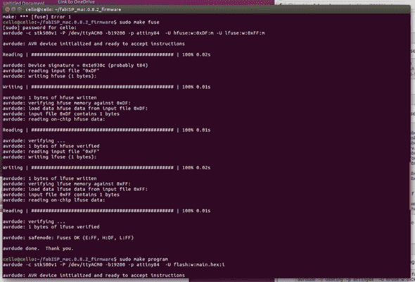
The type:
make program
If it is successful, the following response will be given:
                                cello@cello:~/Desktop/firmware$ sudo make program

                                [sudo] password for cello:

                                avrdude -c usbtiny -p attiny44  -U flash:w:main.hex:i


                                avrdude: AVR device initialized and ready to accept instructions


                                Reading | ################################################## | 100% 0.01s


                                avrdude: Device signature = 0x1e9207

                                avrdude: NOTE: FLASH memory has been specified, an erase cycle will be performed

                                         To disable this feature, specify the -D option.

                                avrdude: erasing chip

                                avrdude: reading input file "main.hex"

                                avrdude: writing flash (2020 bytes):


                                Writing | ################################################## | 100% 5.68s


                                avrdude: 2020 bytes of flash written

                                avrdude: verifying flash memory against main.hex:

                                avrdude: load data flash data from input file main.hex:

                                avrdude: input file main.hex contains 2020 bytes

                                avrdude: reading on-chip flash data:


                                Reading | ################################################## | 100% 3.36s


                                avrdude: verifying ...

                                avrdude: 2020 bytes of flash verified


                                avrdude: safemode: Fuses OK


                                avrdude done.  Thank you.


                                avrdude -c usbtiny -p attiny84  -U hfuse:w:0xDF:m -U lfuse:w:0xFF:m


                                avrdude: AVR device initialized and ready to accept instructions


                                Reading | ################################################## | 100% 0.01s


                                avrdude: Device signature = 0x1e9207

                                avrdude: reading input file "0xDF"

                                avrdude: writing hfuse (1 bytes):


                                Writing | ################################################## | 100% 0.00s


                                avrdude: 1 bytes of hfuse written

                                avrdude: verifying hfuse memory against 0xDF:

                                avrdude: load data hfuse data from input file 0xDF:

                                avrdude: input file 0xDF contains 1 bytes

                                avrdude: reading on-chip hfuse data:


                                Reading | ################################################## | 100% 0.00s


                                avrdude: verifying ...

                                avrdude: 1 bytes of hfuse verified

                                avrdude: reading input file "0xFF"

                                avrdude: writing lfuse (1 bytes):


                                Writing | ################################################## | 100% 0.00s


                                avrdude: 1 bytes of lfuse written

                                avrdude: verifying lfuse memory against 0xFF:

                                avrdude: load data lfuse data from input file 0xFF:

                                avrdude: input file 0xFF contains 1 bytes

                                avrdude: reading on-chip lfuse data:


                                Reading | ################################################## | 100% 0.00s


                                avrdude: verifying ...

                                avrdude: 1 bytes of lfuse verified


                                avrdude: safemode: Fuses OK


                                avrdude done.  Thank you.
6.5 Remove the reset fuse
After the board has programmed
Disconnect the Vcc from the Vprog by removing the solder bridge on the solder jumper and it is ready to use as a programmer to another baord.
To verify that the ISP is working correctly, I have tested using Ubuntu and Windows:
For Ubuntu Type:
lsusb
The following command will be listed in a line:
Bus 002 Device 004: ID 1781:0c9f Multiple Vendors USBtiny
Windows:
Go to Control panel and then device manager:
Finally, we can try to upload our program with the Fab ISP,
6. Line test
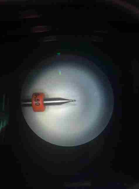
The problem that I have solved is to identify why the milling machine does not cut the pcb properly, and I have found out that the end tool is not sharp anymore. We could take a look this by looking under the microscope.
7. Reference
Building the Fab ISP by Andy Bardajy
8. Download
Hello Board, Fundamentals2017CourseMaterial
Date: 29-05-2018
Author : Marcelo Tania @ Fablab Kamp-Linfort
Created 2018-05-2018 Tue 19:15