Contents
Computer-aided design
1. Objectives
2. 2D Design
4. Raster: GIMP
5. 3D CAD
6. Autodesk Fusion 360
7. References
8. Downloads
1. Objective
The objective of this week is to model a 3D and 2D objets (raster, vector, 2D, 3D, render, animate, simulate). I am going to evaluate and select 2D and 3D software.
2. 2D Desgin
2.1 Introduction
There are two types of software to work on 2D model.One is to work based on pixels where it is good when you want to work with pictures and colour transitions, eg.Photoshop. The second one is working based on vector meaning it is a resolition independent.eg.Ilustrator
2.2 Vector: Illusrator
Illustrator is resolution independent meaning that you could scale and rescale it wihtout taking care of the pixels.
2.2.1 Profile
When you want to start using illustrator, you will get an option which profile do you want to use in your project and each profile has a unique functions. I am going to describe the follwoing profile and their properties.
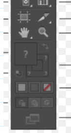
2.2.2 Selection Tool
There are two types of selection tool, Selection Tool and Direct selection tool. Selection tool is to shift the object and rotate. Direct selection tool is to reshape an object. In the direct selection tool, you can reshape an object proportionally by just pressing "shift" on your keyboard and then it will reshape proportionally.

2.2.3 Colour
Choose what colour do you want to draw by selecting the fill colour and stroke colour.

2.2.4 Art board
You can also resize your art board.

2.2.5 Keys
Duplicate hold down "Alt key" with selection tool and drag
Minimize Zoom+Alt
2.2 Fish design
3. Raster: Photoshop
In photoshop we are working in a pixle based so we can see the pixles when we zoom them.
4. Raster: GIMP
I find GIMP very easy to do simple editing like croping and make a any shape for designing a PCB.
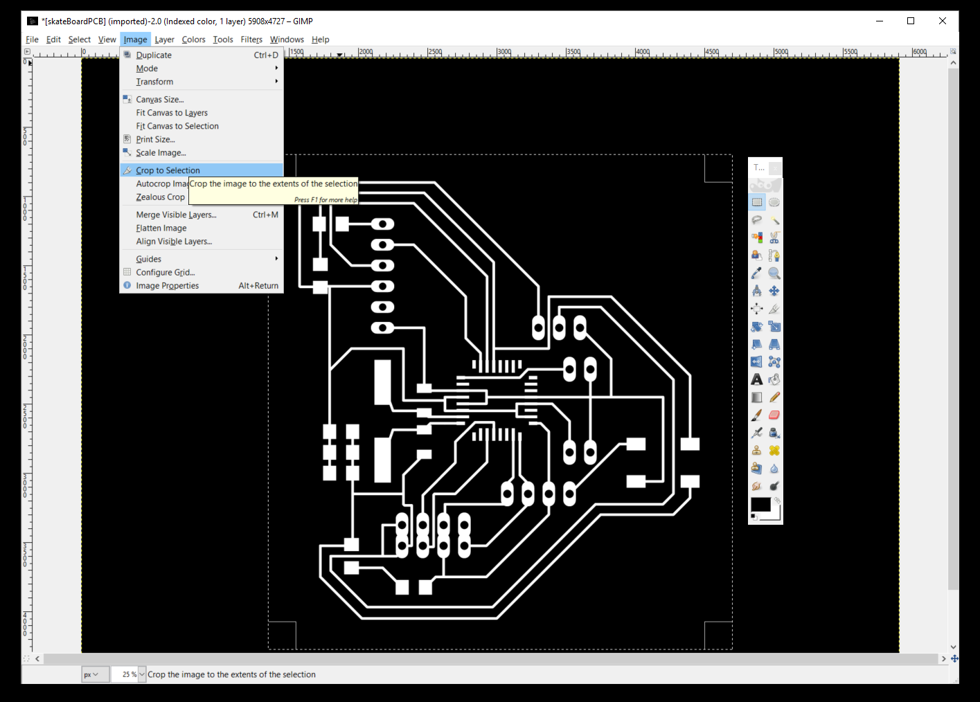
4.1 Draw box and crop

Create a box and then select image and click crop to selection.
I need to cut the line between the pin so I need to draw a box and then delete it with a black colour fill.
4.2 Export
Select file and export image as png.
5. 3D CAD
5.1 Introduction
Since I have tried few 3D CAD softwares like Fusion 360, Rhino and Solidworks . I am very comfortable with solidworks because of the parametric design and easy user interface.
In this exercise I am going to model my final project part and try different softwares.
5.2 Solidworks
5.2.1 Pan and tilt
I am so lucky that I got a chance to help my friend to assembly his pan and tilt system that he has brought in the university. It helps me to understand the mechanism of my future pan and tilt mechanism.
Time to assembly all the parts.
5.3 Download and modify
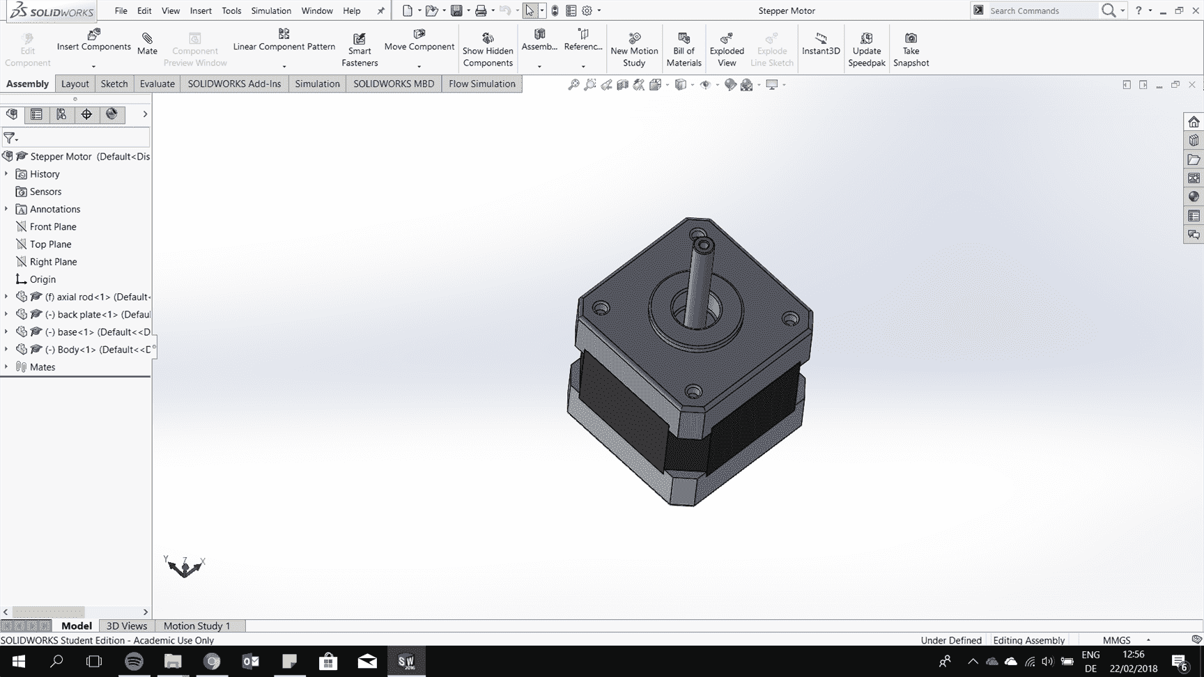
Stepper Motor
First of all to save some time, it is better to download some of the general part from the internet. There are several good website where people share their 3d CAD and in this exercise I have downloaded the screws and the nuts.

This is the website to share and download a 3D CAD of a model : Grab CAD.
For the stepper motor I have designed a stepper motor for my last project and now I just need to measure all the dimension of the stepper motor with vernier caliper.
Sketch all the dimension and I am using the first angle projection.
Thanks to the parametric softaware that we can just easily adjust all the dimension by edit the 2d drawings.

Change the diameter of the holes of the stepper motor head.

The result of the stepper motor that I have.

5.4 Create a new 3D CAD
In this chapter, I am going to give you an overlook how I model the base for the pan and tilt platform using solidworks.
5.4.1 Sketch
First of all you have to sketch by selecting a plane that you want to draw as the canvas.
5.4.2 Extrude
In extrude you have to make sure that the sketch is closed.
5.4.3 Create a plane
I want to draw exaclty on the endge of the outer cylinder, therefore I created a new plane by giving two references.
5.4.4 pattern
All the feuture are going to be the same therefore I copy them 8 pieces by creating an axis at the centre of the cylinder.
5.4.5 Cut-Extrude
Select the sketch and there are option for how much do we want to cut by selecting blind and then give the measurement, through all or up to surface, etc depending on your need.
5.4.5 Fillet
At the end it is good to add some fillet to avoid a notch effect of your model because usually a sharp edges is very easy to be crack and it creae a sharp edge.
6. Autodesk Fusion 360
This is a molding that I have design in Fusion 360 and I still prefer solidworks working on the 3D CAD because it is very easy to sketch and adjust the parameters.