Week 16. machine design
Group Assignment
- actuate and automate your machine
- document the group project and your individual contribution
see FabLab Kamakura's group assignment page.
previously in MTM
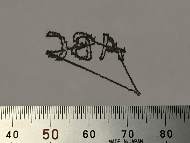
We could sort of actuate and automate our CoreXY, and we had remaining problems. One of them was "mirrored image." Test plot, "ABC," was supposed to be plotted in this way.
But our result was inverted.
individual contribution
I assumed that wirings between motor drivers and NEMA motors caused this glitch. There are four wires between motor drivers and stepper motors, and a pair of two wires corresponds to one of stepper motor phase. Each phase has the sign (positive and negative). That meant sixteen combinations of wiring.
I checked every connection combination to see which direction the pen would move. Here is the result.
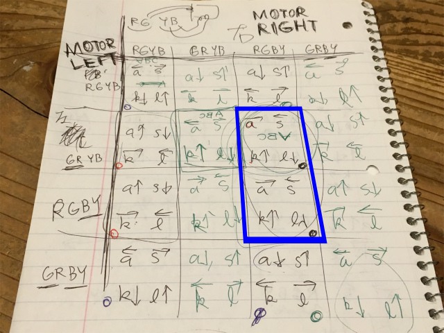
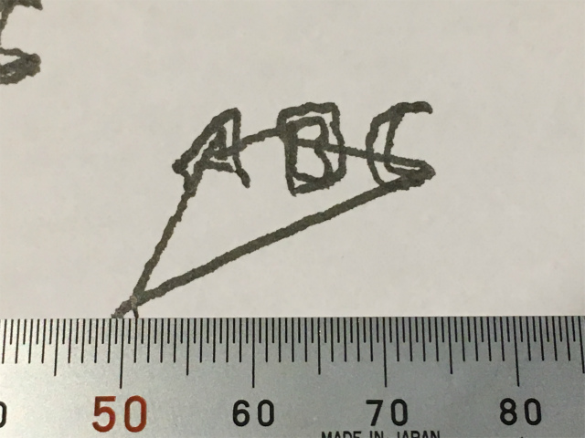
When I chose the combination in a blue solid square, CoreXY was able to plot the right "ABC", but the orientation was not right. The plotted image was rotated 90 or 180 degrees.
I also tried to solve this problem, but I couldn't figure out why. A procedure written in Instructables, "The internal wiring of some motor brands are inversed. If your motor directions are reversed then use the alternate code in the step_motor() function.", failed to help me with this problem.
Anyway, the plotter could write the way I want it to do so. We didn't go any further into this problem.
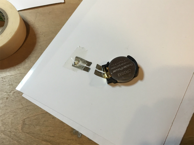
electric contact
Emerging problem was an electrical contact between conductive lines and an electronic component (an LED) because the point-contact was utterly unstable. We used an SMD component, but which raised another problem. The plotter was unable to draw and connect a battery and an LED directly.
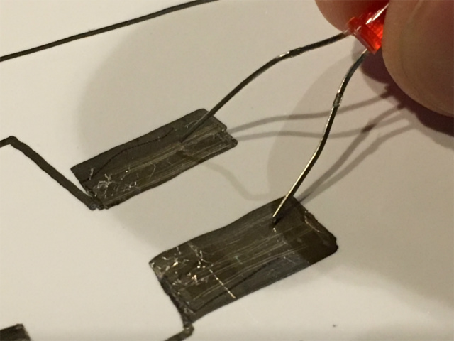
An alternative plan was that I handwrote contact lines beforehand and connect gaps by the CoreXY plotter. I know it's not a smart way, but I didn't aim too high as Neil always said.
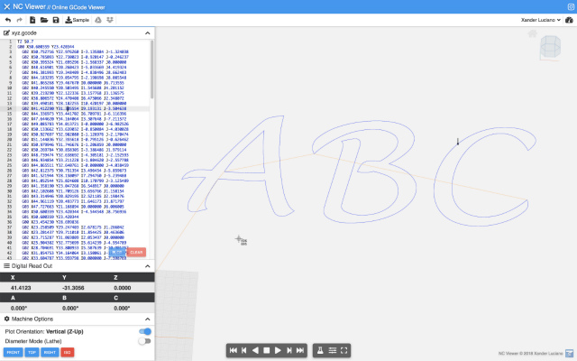
gcode generation
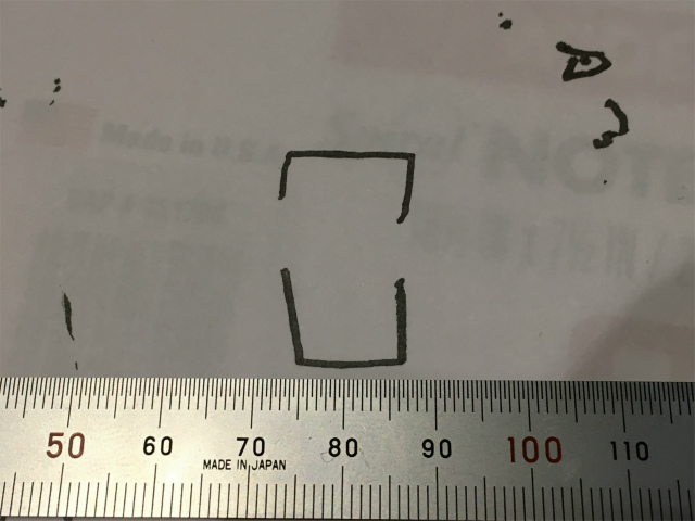
I wanted the plotter to drawn lines like this.
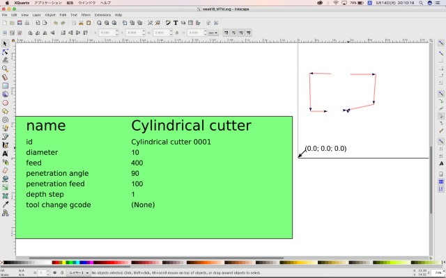
I generated gcode by using an Inkscape extension, gcodetool. I followed this tutorial. Generated gcode was like the image below. I saved it as "circuit.ngc."
sending gcode to CoreXY
I follow another instruction for sending a gcode to a CoreXY plotter.
It used Processing, and I had to change the code depending on my condition.
port = new Serial(this, "/dev/cu.usbmodem141241", 9600); //open 9600 baud serial connection
I ran a Processing program, and send a gcode file, "circuit.ngc," to the plotter. Here is this week's hero shot.
see full description in our grouppage
files
Gcode sender program: Processing code format (.pde)
preparation for gcode: Inkscape format (.svg)
circuit gcode: circuit.ngc (gcode by Inkscape gcodetool) (.ngc)